Automatic Fire Detection using GSM and
Image Processing
Santosh Kumar.M.B
1, Surendra.J
1, Shivanagouda Police Patil
1, Rudramma.S
1, Rajashekar.K
2,
Hanumantha Reddy
2Final year UG Students, Dept. of Electrical & Electronics Engineering, RYM Engineering College, Ballari, Karnataka, India1
Assistant Professor, Dept. of Electrical & Electronics Engineering, RYM Engineering College, Ballari, Karnataka,, India2
ABSTRACT:The project is designed to develop a fire fighting robot using GSM technology for remote operation. The robotic vehicle is loaded with water tanker and a pump which is controlled over wireless communication to sprinkle water. An 8051 series of microcontroller is used for the desired operation. At the transmitting end using push buttons, commands are sent to the receiver to control the movement of the robot either to move forward, backward and left or right etc. At the receiving end three motors are interfaced to the microcontroller where two of them are used for the movement of the vehicle and the remaining one to position the arm of the robot. The GSM transmitter acts as a GSM remote control that has the advantage of adequate range (up to 200 meters) with proper antenna, while the receiver decodes before feeding it to another microcontroller to drive DC motors via motor driver IC for necessary work. A water tank along with water pump is mounted on the robot body and its operation is carried out from the microcontroller output through appropriate signal from the transmitting end. The whole operation is controlled by an 8051 series microcontroller. A motor driver IC is interfaced to the microcontroller through which the controller drives the motors. Further the project can be enhanced by interfacing it with a wireless camera so that the person controlling it can view operation of the robot remotely on a screen.
KEYWORDS: Smoke Sensor, flame sensor, Temperature sensor, image processing, microcontroller, solenoid pump.
I.INTRODUCTION
The project is designed to develop a Automatic Fire Detection using GSM and image Proceesing using GSM technology for remote operation. The robotic vehicle is loaded with water tanker and a pump which is controlled over wireless communication to throw water. An 8051 series of microcontroller is used for the desired operation. At the transmitting end using push buttons, commands are sent to the receiver to control the movement of the robot either to move forward, backward and left or right etc. At vehicle and the remaining one to position the arm of the robot. The GSM transmitter acts as a GSM remote control that has the advantage of adequate range (up to 200 meters) with proper antenna, while the receiver decodes before feeding it to another microcontroller to drive DC motors via motor driver IC for necessary work. A water tank along with water pump is mounted on the robot body and its operation is carried out from the microcontroller output through appropriate signal from the transmitting end. The whole operation is controlled by an 8051 series microcontroller. A motor driver IC is interfaced to the microcontroller through which the controller drives the motors. Further the project can be enhanced by interfacing it with a wireless camera so that the person controlling it can view operation of the robot remotely on a screen.
II. BLOCK DIAGRAM OF PROPOSED SYSTEM
The block diagram of Automatic Fire Detection using GSM and image Processing consists of the following blocks 1. Flame detector
2. Temperature detector 3. Microcontrollers 4. Temperature detector
Figure 1.BLOCK DIAGRAM OF PROPOSED SYSTEM
Flame detector: Flame detectors may comprise an optical sensor for detecting electromagnetic radiation, for example, visible, infrared or ultraviolet, which is indicative of the presence of a flame. A flame detector may detect and measure infrared (IR) radiation, for example in the optical spectrum at around 4.3 microns, a wavelength that is characteristic of the spectral emission peak of carbon dioxide. An optical sensor may also detect radiation in an ultraviolet range at about 200-260 nanometers. This is a region where flames have strong radiation, but where ultra-violet energy of the sun is sufficiently filtered by the atmosphere so as not to prohibit the construction of a practical field instrument. In this Circuit we use photodiode as a sensor which detect the flame which is from electric shot and OPAM is used to amplify the data so that at correct time buzzer is sound.
Temperature detector: The LM56 is a precision low power thermostat. Two stable temperature trip points (VT1 and VT2) are generated by dividing down the LM56 1.250V band gap voltage reference using 3 external resistors. The LM56 has two digital outputs.OUT1 goes LOW when the temperature exceeds T1 and goes HIGH when the temperature goes below (T1±THYST). Similarly, OUT2 goes LOW when the temperature exceeds T2 and goes HIGH
TEMPERATURE DETECTOR
MICROCONTROLLER FLAME DETECTOR
SMOKE DETECTOR
12V SUPPLY GSM MODEM
LCD DISPLAY
230V SUPPLY
when the temperature goes below (T2±THYST).THYST is an internally set 5§C typical hysteresis. The LM56 will be available in an 8-lead Mini-SO8 surface mount package and is currently available in an 8-lead small outline package.
Microcontrollers: Rich in peripherals: The PIC microcontroller has many built in peripherals which can be utilized for various purposes. The 40 pins of 8051 make it easier to use the peripherals as the functions are spread out over the pins. This makes it easier to decide what external devices to attach without worrying too much if there enough pins to do the job.
1) Low power consumption:
The controller works with a low power supply such as 12V DC.
2) Easy programming, cheap and reliable: It is easy in programming with ‘c’ language.
Temperature detector: A GSM modem is a wireless modem that works with a GSM wireless network. A wireless modem behaves like a dial-up modem. The main difference between them is that a dial-up modem sends and receives data through a fixed telephone line while a wireless modem sends and receives data through radio waves. A GSM modem can be an external device or a PC Card / PCMCIA Card. Typically, an external GSM modem is connected to a computer through a serial cable or a USB cable. A GSM modem in the form of a PC Card / PCMCIA Card is designed for use with a laptop computer. It should be inserted into one of the PC Card / PCMCIA Card slots of a laptop computer. Like a GSM mobile phone, a GSM modem requires a SIM card from a wireless carrier in order to operate. Computers use AT commands to control modems. Both GSM modems and dial-up modems support a common set of standard AT commands. A GSM modem is just like a dial-up modem. In addition to the standard AT commands, GSM modems support an extended set of AT commands. These extended AT commands are defined in the GSM standards. The number of SMS messages that can be processed by a GSM modem per minute is very low They are only about six to ten SMS messages per minute.
III.WORKING OF
AUTOMATIC FIRE DETECTION USING GSM AND IMAGE
PROCESSING
IV.METHODOLOGY
The project uses HT12E Encoder which converts 4-bit data to serial output which is then fed to the GSM module for transmitting the same to be received by the receiver RF module the output of which is fed to HT12D the serial decoder IC, the output of which is fed to controller. The transmitting end MC is connected to a set of pushbutton. Thus while a particular button is pressed the program executed delivers corresponding 4-bit data which are then transmitted serially at port 1. The data so received at the receiver end of port 1 operates the motor through motor driver IC L293D as required being interfaced from the Microcontroller output port 2. The transmitter is powered by a 6v battery in series with a silicon diode to finally develop required voltage for microcontroller circuit. The receiver is powered by a 12v battery in series with a silicon diode to protect the circuits from accidental reverse battery connection. 5V DC out of the 12V available from regulator IC 7805 is fed to the controller, decoder, the motor driver IC L293D pin 8 for operation of the motor. The receiving unit uses one more motor driver IC L293D for driving one DC Motor for arm operation with a boom mounted on its shaft. At the end of the shaft a nozzle is connected to a water tanks mounted water pump which is powered from “NO” contacts of a relay that is driven by transistor Q1 from the output of MC pin 15, thus in the event of a fire the robotic vehicle is moved over to the location by operating the left, right, forward & backward button etc. After it reaches the site the nozzle mounted motor takes position through the water on the fire from the water tank mounted DC pump actuated by the relay RL1. Thus the fire can be extinguished.
V. RESULTS AND DISCUSSION
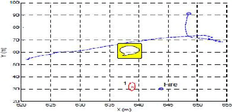
One of the key issues of the COMETS project is the demonstration. The project is being demonstrated in fire detection and monitoring activities, and also forterrain mapping missions.Several experiments with controlled small fires havebeen carried out at Lousa. The controlled fires used in the firedetection tests are originated by the burning of small shrubs.A set of sequences of images containing fire alarms and potential false alarms (heated objects, etc) were recorded. The individual fire segmentation algorithms for infrared and visual cameras, and the data fusion techniques were applied over the images. For each case, the probabilities of detection PD and false positive PF were computed as:PD as the average of the ratio between pixel detected correctly and the complete set of pixels corresponding to fire. PF as the average of the ratio of detected pixels not being fire and the total number of pixels of one image Manually segmented images has been used as groun truth to compute these quantities. Table 1 shows the results of the fusion algorithms. Also, the detection procedure has been applied on actual flights. Figure 9 shows a flight carried out byTable 1 Results of the data fusion algorithms. Algorithm PD PF IR 0.962 0.045 Visual 0.819 0.023 Combined 0.981 0.003 the Helivision helicopter, and marked as 1 the estimated position of the alarm. With the current sensors, the estimated position is within 5 meters of the actual position (recorded by using a GPS).
Fig 2. Actual flight during Lousa experiments. Dashed, trajectory of the helicopter. Labelled as 1, the estimated position of the alarm. The actual
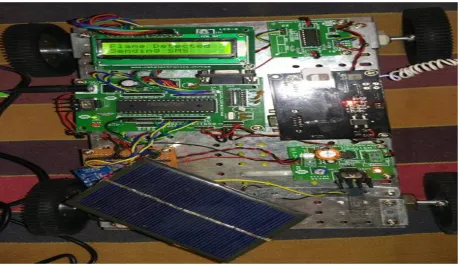
Figure 3 . shows the Automatic Fire Detection using GSM and image Proceesing ,it consists of gsm ,lcd,solar panel, 5v battery, h-bridge, 2v dc motors,water pump and storage tank.
VI.CONCLUSION
This Project presents a Automatic Fire Detection using GSM and image Proceesing using GSM communication and it is designed and implemented with Atmel 89S52 or 8051 microcontroller (MCU) in embedded system domain. Experimental work has been carried out carefully. The result shows that higher efficiency is indeed achieved using the embedded system. The proposed method is verified to be highly beneficial for the security purpose and industrial purpose. At present the robot is capable of throwing water with high flow rate only. At future the robot will also capable of throwing water with controlled robotic arms and the object detection using cameras on it. It can be used as further extension of the project to achieve all the features.
REFERENCES
[1]. Blake,D., Aircraft Cargo Compartment Smoke Detector Alarm Incidents on U.S.- Registered Aircraft, 1974-1999, DOT/FAA/AR-TN00/29, Federal Aviation Administration, Atlantic City, NJ
[2]. Phillips,T., Cabin & Fire Safety: A Perspective From the Cockpit, International Aircraft Fire and Cabin Safety Research Conference, Atlantic City, NJ (1998) Cleary,T., Grosshandler,W., Survey of Fire Detection Technologies and System
[3] Evaluation/Certification Methodologies and Their Suitability for Aircraft Cargo Compartments, NISTIR 6356, NIST, Gaithersburg, MD (1999)Audoin,L., Kolb,G., Torero,J.L., Most,J.M., Fire Safety Journal 1995; 24:167-187
[4]. Goedeke,A.D., Droa,B., Viglione,S., Gross,H.G., Fire detection systems, USPatent 5’153’722 (1992) [5] Foo,S.Y., Knowledge-based systems 1996, 9:531-540
[6] Cheng,X., Wu,J., Yuan,X., Zhou,H., Fire Safety Journal 1999; 33:57-69
[7] Plumb,O.A., Richards,R.F., Development of an Economical Video Based Fire Detection and Location System, NIST GCR 96-695, NIST, Gaithersburg, MD(1996)
[8] EN54: Components of Automatic Fire Detection Systems, European Comitee for Standardisation, July 1982