CSEIT1846206 | Published – 08 May 2018 | May-June 2018 [ (4 ) 6 : 1085-1090 ]
National conference on Engineering Innovations and Solutions (NCEIS – 2018)
International Journal of Scientific Research in Computer Science, Engineering and Information Technology
© 2018 IJSRCSEIT | Volume 4 | Issue 6 | ISSN : 2456-3307
1085
Stability Analysis on Power System
Sanjeevkumar .R .A1, Pooja .k. biradar2, Subin .begum3, Syed Kashif Ali41Assistant Professor, Department of EEE, PDACE, Kalaburagi, Karnataka, India
2,3,4Final year UG students, Department of EEE, PDACE, Kalaburagi, Karnataka, India
ABSTRACT
Stability is an important constraint in power system operation and control .The transient stability is an important aspect in designing and upgrading electric power system. This paper presents the concept of power system stability, reasons for instability and the transient state stability analysis of power system is done using the capacitor bank and induction motor model in the MATLAB/SIMULINK environment. By adding capacitor bank reactive power is improved which in turn enhances the active power of the system. The instability caused by the induction motor is also analysed in this paper.
Keywords: MATLAB/Simulink, stability, capacitor bank, induction motor.
I.
INTRODUCTION
Power system is a vast and major portion of electrical engineering studies. It is mainly concerned with the production of electrical power, its transmission from the sending end to the receiving end as per consumer requirements, incurring a minimum amount of losses. The power at the consumer end often changes due to the variation of load or due to disturbances induced within the length of transmission line. For this reason, the term power system stability is of utmost importance in this field. Another factor that needs to be considered to understand stability well is the stability limit of the system. It is the maximum amount of power delivered from the system without loss of synchronism.
Reasons For Instability
Instability in power system can be caused by a series of events that can lead to the loss of system stability. Power system stability is the ability for the system to find a stable state following an event, stable state
means that all voltages and frequency are in their boundaries and no equipment is under stress.
Each and every power system encompasses various synchronous machines including generators, motors and other rotating machines, which are working in power system by maintaining proper synchronism under all steady state conditions. Synchronism of a power system gets disturbed, when disturbances occur in power system. In other words disturbances occur when the parameters of power system component’s characteristics deviate from their normal working range leading to instability of the system.
Problem formulation
A power system is designed to handle several load demand scenarios. This design is done much in advance (planning stages) based on the expected demand, while keeping some reserve "margins" for situations in which one or more equipment is out of service. However during operation, it is not possible to requisition or install equipment at short notice. Therefore, an operator is forced to ensure that the system is operated within the existing design constraints.
The different constraints in the power system are
Equality constraints:The equality constraints are represented by the power balance constraint, where the total power generation must cover the total power demand and the power loss.
Pg = Pd+ loss
Where Pg = power generated Pd = power demand
Inequality constraints:The inequality constraints are the constraints where the total power generated is not equal to the total power demand and power loss.
Pg ≠ Pd+ loss
Where Pg = power generated Pd = power demand
The inequality constraints reflect the limits on physical devices in the power system as well as the limits created to ensure system security.
Upper and lower bounds on the active and reactive generations:
Upper and lower bounds on the bus voltage magnitude:
Stability constraints: A power system may not be able to cater to power flows beyond a certain point due to stability constraints. An unstable system is
the one which cannot withstand disturbances, i.e., it may not settle to equilibrium although a post-disturbance equilibrium condition may exist. This is due to the basic physical characteristic which defines the behaviour under transient conditions. Improvement of stability may require system reinforcement (like adding new transmission lines) and/or improving/augmenting existing automatic controllers.
II.
ANALYSIS USING CAPACITOR BANK ANDINDUCTION MOTOR CIRCUIT
Single line diagram
Figure 1. Single line diagram of capacitor bank energising circuit
The figure shows the single line diagram of capacitor bank energising model that consist of a 11KV, 30MVA source feeder connected to a 11KV bus, a 1MVA, 11KV/0.4KV transformer the primary of which is connected to the 11kv bus and secondary is connected to 0.4KV bus, a load is connected to the 0.4KV bus, a 11KV capacitor bank is connected to the 11KV bus through the switch and a 0.4KV capacitor bank is connected at the 0.4KV bus through the switch. The stability of the system is analysed in the simulink environment after the switches of capacitor bank are closed one after the other
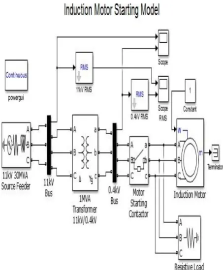
The figure shows the induction motor starting model that consist of a 11KV, 30MVA source feeder connected to a 11KV bus, a 1MVA, 11KV/0.4KV transformer the primary of which is connected to the 11KV bus and the secondary is connected to the 0.4KV bus, an induction motor along with the resistive load is connected at the 0.4KV bus through the switch. The instability caused by the motor is analysed in the MATLAB/Simulink environment.
III.
MPLEMENTATIONUSINGMATLAB/SIMULINK
Figure 3. Simulink model of capacitor bank
By considering a capacitor bank energizing model the reactive power of the system can be improved. This is shown in the above figure.
The capacitor bank energizing model consists of a 11kV 30MVA source feeder, a of 1MVA, 11kV/0.4kV transformer, two buses of 11kV and 0.4kV,two capacitor banks of 11kV and 0.4kV,two capacitor bank contactor of 11kV and 0.4kV and a load.
The disturbances created when both the capacitor contactors are open, when one of them is closed and other open and when both the contactor are closed are studied and the stability of the system is analysed.
Figure 4. Simulink model of induction motor
The induction motor when switched on draws high starting current; this can be studied using the induction motor starting model as shown in the above figure.
The model consist of 11KV, 30MVA source feeder ,a 1MVA, 11KV/ 0.4KV transformer , two buses of 11KV and 0.4KV , a motor starting contactor and a induction motor with an resistive load.
The instability caused by the motor due to high
starting current can be analysed using
IV.
RESULTS AND DISCUSSIONSCapacitor bank energising model
Figure 5.Waveform when both the capacitor bank contactor are open.
The above waveform shows the result of the capacitor bank energizing model when both the capacitor bank contactor are open. The simulation time for the capacitor bank energizing is selected as 0.1 sec (10 cycles). It can be seen that when both the contactors are open there is disturbance at the 11KV bus from the duration 0.02-0.03 sec and 0.04-0.1 sec. At the 0.4KV bus the disturbance occurs from 0.02-0.03 sec.
Figure 6. Waveform when 11kV contactor is open and 0.4kVcontactor is closed.
The above waveform shows the result of capacitor energizing model when the capacitor bank contactor
is open at the 11KV bus and contactor at 0.4KV bus closed. The simulation time for the capacitor bank energizing is selected as 0.1 sec (10 cycles). The simulation results show that the disturbance occurs in the duration 0-0.03 sec and is cleared at 0.03sec at the 11KV bus with the normal operation at 0.4KV bus.
Figure 7. Waveform when 0.4kV contactor is open and 11Kv contactor is closed.
Figure 8. Waveform when both the contactors are closed.
The above waveform shows the result of the capacitor bank energizing model when both the capacitor bank contactor are closed. The simulation time for the capacitor bank energizing is selected as 0.1 sec (10 cycles). From the simulation results it can be seen that when both the contactors at the buses are closed the power generated from the source is delivered to the load efficiently without any disturbances. Hence when a capacitor bank is connected at the load side where the disturbance occurs more, these disturbances are reduced with the use of capacitor banks that increases the reactive power which in turn enhances the active power at the load and thus the system become balanced.
V.
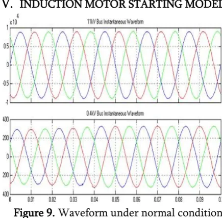
INDUCTION MOTOR STARTING MODELFigure 9. Waveform under normal condition
The figure 9 shows the supply waveform of all the three phases supplied to the induction motor connected to the load bus. It can be seen that the magnitude of the voltage in all the three phases remains the same at both the buses.
Figure 10. Induction motor characteristics during starting
later the voltage starts to increase exponentially and becomes stable at 0.25sec. Similarly the voltage magnitude of all the three phases at0.4kv bus decreases’ suddenly that leads to the instability and the voltage increases gradually after and results in the stable system.
VI.
CONCLUSIONThe stability of the system is studied and analysed using capacitor bank energising model and the induction motor starting model. The induction motor characteristics during starting and under normal condition are studied and the simulation results shows that when a capacitor bank is connected at the load side where the disturbance occurs more, the disturbances are reduced and the reactive power is improved which in turn enhances the active power at the load and thus the system becomes stable.
VII.
REFERENCES1. “A review of concepts in power system stability”, Yaqoub AL Shamli, Nasser Hosseinzadeh, Hasan Yousef.
2. “Power system stability and control”, Prabha Kundur.
3. “Transient stability analysis of the IEEE 14-bus electric power system”, P.K.Iy ambo, R.Tzoneva. 4. “A power system transient stability analysis
based on MATLAB”, Ying Wang, F.S.Wen, S.F.Yang.
5. “Power system stability: modelling, analysis and control”, Om Mallik, Abselhay A.Sallam.
6. “Power system operation and control”, Uma rao.
7. “MATLAB/Simulink based modelling and
simulation of power quality disturbances”, S.Khokhar, A.A.Mohd.Zin, NAM Ismail.