R E S E A R C H
Open Access
Asynchronous analog-to-digital converter based
on level-crossing sampling scheme
Mohammadmehdi Kafashan
*, Sajjad Beygi and Farrokh Marvasti
Abstract
In this paper, a new iterative algorithm is used to convert analog signals to digital (A/D) using an asynchronous A/ D converter. It is a realtime system, which encodes the amplitude information of the analog signal into a time sequence. In particular, using asynchronous systems for data conversion is an effective technique in order to reduce power consumption. The decoder should recover original signal from irregular samples. If a more intelligent reconstruction technique is used for decoding, signals with higher bandwidth can be digitized. In this work, we employ delta- and sigma-delta level-crossing sampling schemes. These asynchronous A/D converters are simple to implement and have very good performance with lower power consumption.
Keywords:signal reconstruction, analog-to-digital converter, level-crossing sampling, iterative algorithm
1 Introduction
Analog-to-digital converters have many applications in digital signal processing and communication systems. Conventional A/D converters consist of two steps: sam-pling operation followed by digital quantization. The noise introduced by signal distortion due to quantization decreases the A/D performance. In the literature, the performance of A/D converters is measured by the number of bits per sample and signal-to-noise ratio (SNR) [1,2].
Uniform sampling is used for synchronous implemen-tation where a common clock is operated in order to convert analog signals to digital values. In the sigma-delta modulator, the original signal is highly over-sampled and the internal clock operates at a much higher rate than the bandwidth of the signal; however, the oversampled signal down-sampled at the last stage of A/D converter. On the other hand, most of the sig-nals generated by temperature sensors, pressure sensors, electro-cardiograms and speech signals are almost always constant and may vary significantly for only brief moments [3,4]. Thus, conventional converters using uni-form sampling at the Nyquist rate are limited in the implemented signal bandwidth, but asynchronous
converters can be used in order to decrease the internal clock rate.
Asynchronous converters can be implemented without a global clock and have interesting properties, such as low power consumption and reduction of electromag-netic interferences. A nonuniform sampling scheme is used for this aim. In this process, several reference amplitude levels are considered in the dynamic range of the input signal. A sample must be taken only when a reference level is crossed. In this case, samples are not spaced regularly, and the sampling rate depends on the input signal. In other words, when the input signal become active, the sampling rate is increased and vice verse. In the level-crossing scheme, two sets of the time instant and amplitude levels of the samples are saved. This sampling scheme is the dual of the uniform sam-pling, where the time instants are quantized, while the amplitudes are perfectly known [5-9].
In this paper, a new class of A/D converters based on the level-crossing scheme is investigated. Asynchronous delta- and sigma-delta modulation are analyzed in order to minimize the activity, decrease the power consump-tion of the converters and achieve a good SNR. The next section describe synchronous and asynchronous A/ D converters in relation to the iterative decoding algo-rithm. In sections 3 and 4, the new contributions of this paper are presented, and finally Section 5 concludes this paper.
* Correspondence: [email protected]
Electrical Engineering Department and Advanced Communications Research Institute (ACRI), Sharif University of Technology, Tehran, Iran
Kafashanet al.EURASIP Journal on Advances in Signal Processing2011,2011:109 http://asp.eurasipjournals.com/content/2011/1/109
2 Basic principles
2.1 Synchronous A/D converter
In synchronous converters, uniform samples quantized to approximate a continuous range of values by a speci-fic set of discrete values. The quantization process incurs loss of information in the reconstructed signal. Subsequently, the reconstructed signal may differ con-siderably from the original analog signal. In order to overcome this problem, we must use oversampling con-verters. In the oversampling converters, sampling rate is greater than Nyquist rate (fNyquist = 1/τNyquist). The ratio between the sampling rate and twice the signal band-width is defined as the oversampling ratio (OSR). After oversampling, the signal is subject to quantization and then low-pass filtered and finally down-sampled to or near to the Nyquist rate (known as decimation) [10].
The two main types of oversampling converters are delta modulators (DM) and sigma-delta modulator (SDM). The SDM is a kind of A/D converter derived from delta modulation. The principle of the sigma-delta architecture is to make rough evaluations of the signal, to measure the error, and then integrate and compen-sate for that error [11]. In SDM converter, we have fol-lowing equation
xn−qn=mun (1) whichxis our original analog signal andq is the out-put of A/D converter. Here,Δis the difference operator, which can be defined byΔun=un-un-1. We have defined auxiliary sequenceu as the state sequence. This explicit factorization of the quantization error is useful ifuis a bounded sequence. It means that SDM, which is deter-mined from (1), is unstable and impractical unless the sequenceuis bounded. The relation (1) is valid for n> 0, and we consider un = 0 for n < 0 (this state is an initial condition for a recursive relation (3)). In practice, the sequenceucan be obtained by integrating the differ-ence equation (1) based on an associated “quantization rule,”
qn=Q(un−1,un−2, ...,xn,xn−1, ...) (2)
Consequently, the output bit streamqn can be gener-ated by using (2), and the sequenceu can be expressed as
un= n
k=1
(−1)k−1mk+un−k+xn−qn (3)
The mathematics of sigma-delta A/D conversion is extremely challenging. Here, we use following difference equation to introduce an SDM scheme of order m.
If we consider one-bit quantizer as the quantization rule, the auxiliary sequencesucan be achieved from the
following relation
un=un−1+xn−sign(un−1+xn) (4) In order to have a bounded sequenceu, yandqmust
not be unrelated sequence because u is determined
fromy- qvia (1). Therefore,Qmust be such to tieqto
yto controlu.
2.2 Asynchronous A/D converter
In asynchronous converters, we deal with nonuniform sampling and the original signal should be reconstructed from two sets of time instants (tk) and the correspond-ing amplitude values. Nonuniform samplcorrespond-ing uscorrespond-ing level-crossing method is shown in Figure 1. In this type of converter, the time difference between irregular samples should be quantized and transmitted. Therefore, we need a local timer instead of an amplitude quantizer, and the quality of the A/D converter is related to the precision of local timer (Tc). By reducing the value of
Tc, the SNR of the reconstructed signal can be
improved.
There are many methods to reconstruct the original signal from nonuniform samples. Reconstruction can be performed by using the TVa method [12], the lagrange
method [13] and the CFTbmethod [14]. Suppose that
(tk,kZ) are increasing time instants of a irregular sam-ples. Subsequently, nonuniform samples xs(t) can be written as xs(t) =iεkx(ti)δ(t−ti). The sampling set
(xtk,kεZ)should be a stable sampling set. This means that this set of samples uniquely determines signal x(t) and, for this reason, the relation |x(t)|2dt≤C
i|x(ti)|2 should be satisfied, whereCis a constant. For instance, if |tk-kτ| < (τ/4), the set is stable (τis the Nyquist sam-pling rate).
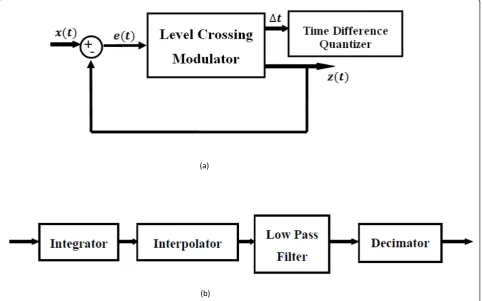
The iterative method is used in order to recover the original signal x(t) from its nonuniform samples,xs(t) [15]. The block diagram of an iterative algorithm is shown in Figure 2. In this scheme, G is a distortion operator (it is known from the modulator and demodu-lator that caused the distortion in the input signal). The iterative algorithm is given by
xk+1(t) =x0(t) + (I−G)xk(t) (5) wherexk+1 (t) is thekth iteration andx0(t) can be any function of time. However, x0(t) = G(x(t)) is a good choice to achieve faster convergence. In general,Gcan be either a linear or nonlinear operator. By defining the operatorsGˆ =λGandE=I− ˆG, we can rewrite (5) as
Figure 1Nonuniform sampling using level crossing method.
Figure 2The configuration of iterative method.
Kafashanet al.EURASIP Journal on Advances in Signal Processing2011,2011:109 http://asp.eurasipjournals.com/content/2011/1/109
xk(t) = (Ek+Ek−1+· · ·+E+ 1) (7) If Gis considered as a linear operator, then we have the following relation
Ek+Ek−1+· · ·+E+ 1 =I−E
k+1
I−E (8)
If the norm of operator E satisfies ||E|| < 1, by increasing the number of iterations k, (6) approaches the inverse system Ĝ(as it is shown in (8)); therefore,xk (t) converges toxt.
In our problem concerning the signal from nonuni-form samples, distortion operator ofGis a interpolator and a low-pass filter. Nonuniform samples pass from an interpolator in order to uniform, and then, a low-pass filter is used to remove the high frequency of the output of the interpolator. The SNR of reconstructed signal is dependent on the order of low-pass filter. the iterative method is a good idea to improve A/D performance without using a complicated filter.
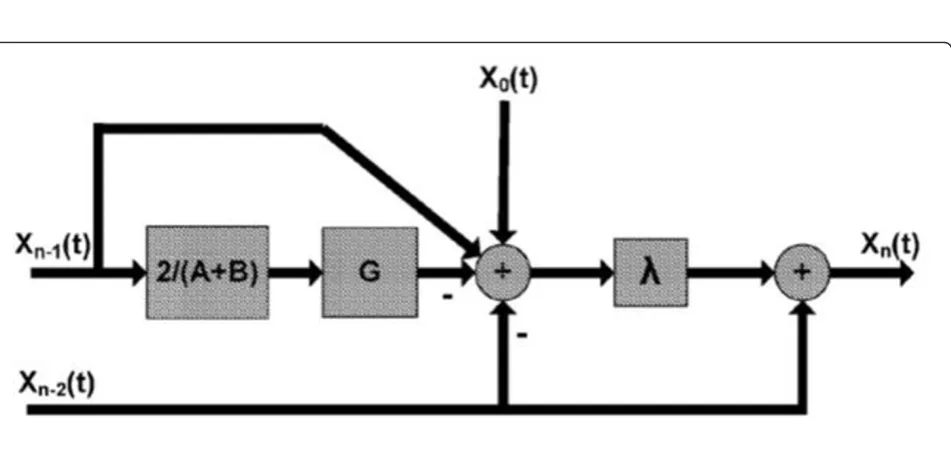
The convergence rate of the iterative method can be increased by using the Chebyshev acceleration (CA) algorithm. The block diagram of this method is shown in Figure 3. The convergence rate of the conventional iterative method is low even for the optimum parameter. By using the CA method, we can improve the iteration algorithm with relatively little additional complexity. The acceleration method can be stated as
xn=λn
x1+xn−1− 2
A+BG(xn−1)−xn−2
+xn−2 (9)
wherex0 =G(x(t)) and x1= 2
A+Bx0Gis the distortion
operator, which is defined in the previous section. In
order to obtain a good performance,Aand Bmust be
chosen properly (they have to be selected by numeri-cally). Also,lncan be determined as follows:
λn=
1−ρ 2
4λn−1
−1
(10)
whereris expressed as
ρ= B−A
B+A (11)
The iterative method is used to improve the perfor-mance of synchronous A/D converters, too. In the case of synchronous SDM converters, distortion operator (G) comprise of a sigma-delta modulator and a low-pass fil-ter (LPF) to remove the shaped quantization noise. The block diagram of operator G for a first-order sigma-delta modulator is shown in Figure 4.
3 Asynchronous delta modulator
In an asynchronous A/D converter based on level-cross-ing scheme, the conversion of samples takes place whenever a reference level is crossed. The number of reference levels depends on the dynamic range of the continuous input signal. In delta level-crossing conver-ters, difference between the input signal and the output of the converter is passed from a level-crossing sampler. In this case, the dynamic range of the input of the level-crossing sampler and, consequently, the number of
reference levels is decreased. Therefore, the number of bits that are allocated to the amplitude of the input sig-nal is reduced. The amplitude and time of each con-verted sample should be considered for digital transmission. The time difference between two consecu-tive samples is quantized instead of the time of each sample in order to prevent quantization error
propagation. In asynchronous DMs, the dynamic range of the input signal should be known in order to specify the number of reference levels and determine the inter-val between them.
The modulator of asynchronous DMs is shown in Fig-ure 5a. Reconstruction of the original signal from the output of the modulator is depicted in Figure 5b. As Figure 4Block diagram of distortion operator G for synchronous first-order sigma-delta modulator.
(a)
(b)
Figure 5(a) Modulator of delta level crossing; (b) Demodulator of delta level crossing.
Kafashanet al.EURASIP Journal on Advances in Signal Processing2011,2011:109 http://asp.eurasipjournals.com/content/2011/1/109
can be seen in this figure, the nonuniform sampling obtained from the level-crossing sampler is passed from an integrator. The integrator assumes that irregular samples are uniform, and then, integration is performed. Subsequently, the output integrator, which is a set of nonuniform samples, is passed from the interpolator, and uniform samples are achieved. The approximation of the original input signal is obtained by applying a low-pass filter to the output of interpolators in order to suppress the high-frequency components of the interpo-lated signal. A decimator is used at the final stage to reduce the sampling rate to the Nyquist rate.
The SNR of asynchronous DM is the same as the SNR which is derived in [4]. Suppose thatδt is the error of time quantization. Then, the amplitude error of recon-structed signal will beδV, which can be derived from the input signal andδt[16] with the following: equation
δV1= dV1
dt .δt (12)
In Equation (12),V1 is the input of the level-crossing sampler, which is obtained from a delta modulation
scheme, and dV1
dt is its slope. The quantization noise
powerP(δV1), in the case that
dV1
dt andδtare considered
as independent random processes, can be obtained from the following formula:
P(δV1) =P( dV1
dt ).P(δt) (13)
In each time instant,V1 is the input analog signalVin subtracted from a previously selected reference level.
Therefore, dVin
dt is equal to
dV1
dt and SNR for
asynchro-nous delta modulation can be written as
SNRdB= 10. log(3
P(Vin)
P(dVin dt )
) + 20. log( 1
TC
),
(14)
whereP(Vin) andP
dVin dt
are the power of the input
signal and its derivation, respectively The time differ-ence of between consecutive samples is quantized according to the precision Tc timer. It can be under-stood from above equation that, by decreasing the value ofTc and increasing the precision of the time quantizer, the SNR of reconstructed signal will be increased.
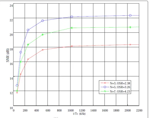
In asynchronous converters, the oversampling ratio is not an integer number and depends on the statistical characteristics of the input signal. The SNR of the reconstructed signal versus the precision of the time
quantizer
1
TC
for different over sampling rates is
shown in Figure 6. In this figure, N is the number of bits for the amplitude quantizer (it specifies the interval between reference levels). It can be seen in this figure that, for a specific OSR, the SNR of the reconstructed signal is increased by increasing the frequency of the
time quantizer
1
TC
. After a threshold value for TC,
increase in the SNR is trivial. The same results (e.g., Fig-ure 5) will be obtained for the level-crossing converter when the number of quantization bits is 9, 7 and 5. On the other hand, by using the delta level-crossing, the number of reference levels is decreased to 105 (7 bits), 25(5 bits) and 7 (3 bits). The number of bits that are needed to encode the difference time of between
sam-ples for different timer resolutions
1
TC
is shown in
Table 1. As expected, by increasing the sampling rate, the distance of between the samples is decreased and it causes a reduction in the number of reference levels (bits that are needed for amplitude quantizer).
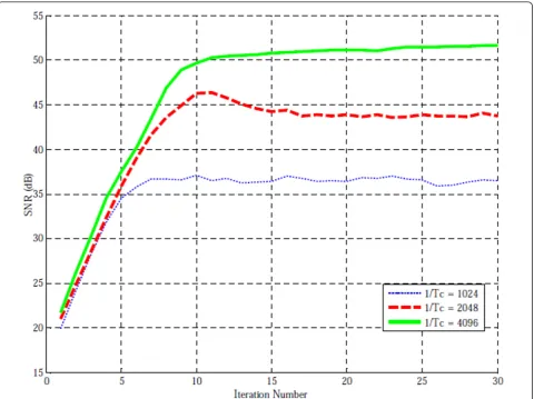
The iterative algorithm is used in order to improve the performance of delta level-crossing converter. The distortion operator G consists of the modulator and demodulator of the delta level-crossing converter, excluding the decimator module in the demodulator. In this method, the optimal lis obtained in way that the SNR in its saturate value after 10 iterations will be max-imum. SNR versus the iteration number for three differ-ent timer resolutions is illustrated in Figure 7. It can be comprehended from this figure that for a specific timer resolution, the SNR of the reconstructed signal cannot be enhanced by increasing the number of iterations after a certain threshold. Hence, in order to improve the SNR of the reconstructed signal, the precision of time quantizer should be increased.
4 Asynchronous sigma-delta modulator
The asynchronous sigma-delta modulator can be imple-mented without any clock and can operate at low supply power because of its asynchronous design and simple corresponding circuitry. In synchronous SDM A/D con-verters, a high dynamic range is achieved. However, there is a large number of coarsely quantized samples. By combining the SDM with the level-crossing scheme, the number of converted samples is decreased and a high dynamic range is obtained. The modulator of this converter consists of an integrator and a level-crossing sampler in a negative feedback loop.
level-crossing sampler to uniform samples. Then, a decimator is used in order to reconstruct the original signal from interpolated samples in Nyquist rate. In a simple model for the asynchronous sigma-delta modulator, the error of level-crossing sampler is considered as an additive noise. Therefore, it can be realized that the error signal passes from a high-pass transfer function to receive in the output of the modulator and it causes noise shaping, which can improve performance of the system.
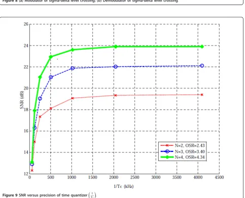
The SNR of the reconstructed signal versus the
preci-sion of the time quantizer
1
TC
for different over
sam-pling rates is shown in Figure 9. Similarly to Table 1, the number of bits that are needed to encode the differ-ence time between samples for different timer
resolu-tions
1
TC
is shown in Table 2. A comparison between
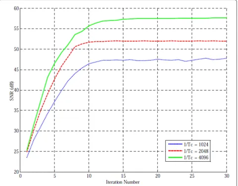
Table 1 and Table 2 shows that maximum distance between samples in asynchronous SDMs is smaller than those in asynchronous DMs and it leads to a smaller number of bits for the time quantizer. The SNR versus the iteration number for three different timer resolu-tions is illustrated in Figure 10.
The total power consumption of the converter after a specific number of iterations (N) can be obtained easily by multiplying the power of the one iteration by N. Dynamic power consumption is related to switch tran-sitions and operating frequency of the circuit, while Figure 6SNR versus precision of time quantizer
1 TC
.
Table 1 Number of bits for reference levels versus precision of time quantizer
1 TC
Timer resolution (kHz) OSR = 2.38 OSR = 4.23
64 6 5
128 7 6
256 8 7
512 9 8
1,024 10 9
2,056 11 10
Kafashanet al.EURASIP Journal on Advances in Signal Processing2011,2011:109 http://asp.eurasipjournals.com/content/2011/1/109
static power consumption is directly related to the technology, which is used for the A/D converter imple-mentation and should be measured after practical implementation of the converter [17]. Dynamic power consumption for our asynchronous converter can be obtained from the following equation:
Pdynamic=fS·CLoad·(Vdd)2+fclc·CLoad·(Vdd)2. (15) Where,CLoadandCLoadare approximately in the range of (1-2) Picofarad and (100-200) Femtofarad, respec-tively. Also,fSandfclcare operating frequency of the cir-cuit (OSR *fNyquist) and frequency of the timer clock, respectively. The right term of the above equation is the power, which is consumed by the timer clock. By com-paring the operating frequency of the circuit in the syn-chronous and asynsyn-chronous converter with each other, it can be understand that asynchronous circuits are very effective converters in order to reduce dynamic power consumption.
A first-order asynchronous sigma-delta modulator is used in our simulation. Therefore, we compare its results with a first-order synchronous sigma-delta mod-ulator. The number of quantization level for synchro-nous converters is considered equal to the number of reference levels in asynchronous one. The simulation results can be observed in Table 3. It can be found from this table that good enhancement in the converter can be achieved by using the level-crossing sampler instead of the amplitude quantizer in a sigma-delta converter. On the other hand, the complexity (simulation time T) in an asynchronous converter is greater than that of an synchronous one. Also, it can be seen that, by increasing the timer resolution, the SNR of the reconstructed sig-nal is increased and the SNR in the case that
1
TC
= 8, 192is about 7dB better than 1
TC
= 4, 096after
10 iterations.
(a)
(b)
Figure 8(a) Modulator of sigma-delta level crossing; (b) Demodulator of sigma-delta level crossing.
Figure 9SNR versus precision of time quantizer
1 TC
.
Kafashanet al.EURASIP Journal on Advances in Signal Processing2011,2011:109 http://asp.eurasipjournals.com/content/2011/1/109
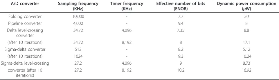
A/D converter. It can be found from this table that the resolution and dynamic power consumption of the asyn-chronous SDM converter after 10 iterations are more than other converters. However, one iteration of an asynchronous converter consumes less power than a synchronous converter.
5 Conclusion
This paper presents a new iterative algorithm to convert analog signal to digital (A/D) using an asynchronous A/ D converter. In the proposed methods, converted sam-ples are nonuniform, which decreases the number of additional samples and lead to decreasing in the power consumption. Simulation results demonstrate that the asynchronous sigma-delta modulator has better perfor-mance than the synchronous one, and its quality even can be enhanced by increasing the timer resolution.
The iterative algorithm is effective way to reconstruct original signal from the nonuniform samples of the asynchronous converter. Therefore, we use the iterative method to improve performance of these A/D conver-ters and decrease the distortion caused by the SDM modulator. Hence, we can exploit filters with lower
Table 2 Number of bits for reference levels versus precision of time quantizer
1 TC
Timer resolution (kHz) OSR = 2.43 OSR = 4.34
64 5 4
128 6 5
256 7 6
512 8 7
1,024 9 8
2,056 10 9
degree in order to decrease the cost and complexity of the A/D converter.
These A/D converters have many applications because of their simple structure and low power consumption. Implementation of the iterative algorithm is simple, and it is unnecessary to change the configuration of the A/D converter in order to increase the number of iterations. Also, it must be mentioned that using the iterative algo-rithm to improve the performance of the system sup-ports all types of SDMs with different orders and different numbers of quantization bits.
Endnotes
a
Time Varying.bCompound Fourier Transform.
Authors’contributions
All authors participated in the preparation of the paper. MK developed the model and wrote the paper. Also, some part of the simulations are accomplished by MK. SB was involved in performing the simulations and verifying the results, and FM supervised all the work. All the authors contributed to the manuscript, and approved its final version.
Competing interests
The authors declare that they have no competing interests.
Received: 19 January 2011 Accepted: 23 November 2011 Published: 23 November 2011
References
1. J Candy, A Huynh, Double interpolation for digital-to-analog conversion. IEEE Trans Commun.34(1), 77–81 (1986)
2. R Walden, Analog-to-digital converter survey and analysis. IEEE J Sel Areas Commun.17(4), 539–550 (1999). doi:10.1109/49.761034
3. M Renaudin, Asynchronous circuits and systems: a promising design alternative. Microelectron Eng.54(1-2), 133–149 (2000). doi:10.1016/S0167-9317(00)80065-9
4. E Allier, G Sicard, L Fesquet, M Renaudin, Asynchronous level crossing analog to digital converters. Measurement.37(4), 296–309 (2005). doi:10.1016/j.measurement.2005.03.002
5. AA Lazar, Time encoding with an integrate-and-fire neuron with a refractory period. Neurocomputing 58–60 (2004). 53-58
6. J Mark, T Todd, A nonuniform sampling approach to data compression. IEEE Trans Commun.29(1), 24–32 (1981). doi:10.1109/TCOM.1981.1094872 7. N Sayiner, H Sorensen, T Viswanathan, A level-crossing sampling scheme for
a/d conversion. IEEE Trans Circuits Syst II: Analog DigitSignal Process.43(4), 335–339 (1996). doi:10.1109/82.488288
8. I Blake, W Lindsey, Level-crossing problems for random processes. IEEE Trans Inf Theory19(3), 295–315 (1973). doi:10.1109/TIT.1973.1055016 9. M MalmirChegini, F Marvasti, Performance improvement of level-crossing a/
d converters. IEEE International Conference on Telecommunications and Malaysia International Conference on Communications ICT-MICC, 438–441 (May 2007)
10. M Kozak, I Kale,Oversampled Delta-Sigma Modulators Analysis, Applications and Novel Topologies(Kluwer, Boston, MA, 2003)
11. R Schreier, G Temes,Understanding Delta-Sigma Data Converters, (Wiley, New York, NY, 2004)
Table 3 SNR of reconstructed signal for asynchronous and synchronous sigma-delta modulator for different iteration numbers
Iteration number Sigma-delta level crossing Sigma-delta
OSR = 3.40 OSR = 16 OSR = 32 OSR = 64
N = 3 N = 3 N = 3 N = 3
1 TC
= 4, 096 kHz 1
TC
= 8, 192 kHz T = 1.14 s T = 1.23 s T = 1.39 s
T = 6.65s T = 7.11s
5 46.47 51.10 37.21 42.18 50.73
10 55.71 63.29 43.60 51.03 57.59
15 57.28 64.09 44.34 51.08 58.61
20 57.51 64.26 45.05 51.17 58.83
30 57.69 64.78 45.18 51.52 58.88
Table 4 sampling frequency, dynamic power consumption and effective number of Bits for different A/D converter [18,19]
A/D converter Sampling frequency (KHz)
Timer frequency (KHz)
Effective number of bits (ENOB)
Dynamic power consumption (μW)
Folding converter 10,000 - 7.7 20
Pipeline converter 4,000 - 9.4 8
Delta level-crossing converter
34.72 4,096 7.35 8.8
(after 10 iterations) 34.72 8,192 8 17.1
Sigma-delta converter 512 - 8.2 5.12
(after 10 iterations) 1024 - 9.3 10.24
Sigma-delta level-crossing 27.2 4,096 9 8.73
converter (after 10 iterations)
27.2 8,192 10.2 16.92
Kafashanet al.EURASIP Journal on Advances in Signal Processing2011,2011:109 http://asp.eurasipjournals.com/content/2011/1/109
12. F Marvasti, P Clarkson, M Dokic, U Goenchanart, C Liu, Reconstruction of speech signals with lost samples. IEEE Trans Signal Process.40(12), 2897–2903 (1992). doi:10.1109/78.175734
13. F Marvasti,Nonuniform Sampling: Theory and Practice, (Kluwer/Plenum, New York, 2001)
14. R Piroddi, M Petrou,Analysis of Irregularly Sampled Data: A Review,Ser Advances in Imaging and Electron Physics, vol. 132. (Elsevier, 2004), pp. 109–165
15. M Ghandi, MMJ Yekta, F Marvasti, Some nonlinear/adaptive methods for fast recovery of the missing samples of signals. Signal Process.88(3), 624–638 (2008). doi:10.1016/j.sigpro.2007.09.004
16. E Allier, G Sicard, L Fesquet, M Renaudin, A new class of asynchronous A/D converters based on time quantization. IEEE International Symposium on Asynchronous Circuits and Systems, ASYNC. 196–205 (May 2003) 17. R Plassche,CMOS Integrated Analog-to-Digital and Digital-to-Analog
Converters(Kluwer, Boston, MA, 2003)
18. H van der Ploeg, B Nauta,Calibration Techniques in Nyquist A/D Converters, vol. 873 (Springer, Dordrecht, 2006)
19. C Taillefer, Analog-to-digital conversion via time-mode signal processing, PhD Thesis, McGill University (2007)
doi:10.1186/1687-6180-2011-109
Cite this article as:Kafashanet al.:Asynchronous analog-to-digital
converter based on level-crossing sampling scheme.EURASIP Journal on
Advances in Signal Processing20112011:109.
Submit your manuscript to a
journal and benefi t from:
7Convenient online submission
7Rigorous peer review
7Immediate publication on acceptance
7Open access: articles freely available online
7High visibility within the fi eld
7Retaining the copyright to your article