SEPARATOR SET Pt>V8:3464:'
THls..Sf.PARATOR:. SEt ,COtfr-AINS 19·
TABS TOTAL .IN THE)'oi,iQW1NG< _.ORDER:
MAINTENANCg,·MANUAL. . . . . ...
;j.-1. I N rR:Op~~TloN .
:'L ·!-N"STAlLAitON- .
4~ ·STGR,A:~E.r£~::~J~J~"CE~·,
5.: JNDUST~¥.;·I!'lTe:~~:~CE,
6.:~SCSf: INTERFACE
7~ ·YS .H'i~iRFACE'
a~ F UNC ·TloNAi....Pes'6R::~r'fON 9.:MAINJENANCE ~.
1 Q-~. RE MO VAL1REP~~C'tMbn' .1 1._ D I AGNOST I Cs
APPENDICES IPC
PN COMPATIBILITY MMlL
21/22/25 STD & 25 IND SiD'FCD 21/22 IND STD FCD
Storage Technology C.orporation
2920:
Tape
S~Q~x~t~m
.~. .Maintenance. M.anual
'" • ..;~ . . . . : ~ :;-"'. "'~ . 'I. ~'~ • • '
Ihformation contained in this publication is subject to change. In the event of changes, the publication will be revised. Comments concerning the contents of this manual should be directed· to Technical Publications at -the address below.
This publication was prepared by Storage Technology CorporatioQ, Technical Publications, 2270 South 88th Street, . Louisville, Colorado 80028-2286.
Copyright @ 1987
by
LIST OF EFFECTIVE PAGES
Manual PN
95521Issue Date:
AUGUST 1983 EC 49546
Reissue Date:
Change Date: APRIL 1988 CHANGE 5 EC 26275 KIT
PN
88219Incorporates
EC:
26275Total number of pages in this document is 410. consisting of the fo 110wi ng pages:
PAGE
Ti t le i i i i i
iv thru xxi i
~ - 1
1 - 11 thru 1-12 2-1 thru 2-24 3-1 thru 3-32 4-1 thru 4-48 5-1 thru 5-28 6-1 thru 6-74 7-1 thru 7-30 8-1 thru 8-20 9-1 thru 9-12 10-1 thru 10-2 10-3
10-4 thru 10-28
11 - 1 thru 11-7
11-8 thru 11- 18 11 - 19 and 11 - 20 A-l thru A-2 B-1 thru B-8
C-l thru C-6
D-1 thru 0-6 E-1 thru E-6 F - 1 thru F-10 G-l thru G-2
Index 1 thru 10
Reader's Comment Form Business Reply Mailer
EC NO.
26026 26275 26026 26026 23585 26026 26026 26026 26275 26026 26026 26026A 26026A 23585
KIT PN
DISPOSITION
88063
88219 Replace
88063 88063 83440 88063 88063 88063
88219 Replace
88063 88063 88171 88171
TABLE OF CONTENTS
Paragraph Tit 1 e
CHAPTER 1 GENERAL !NFORMA TION
1 • 1 1 .2
1 .2. 1 1 .2.2
1 .2.3
1 .2.4
1 .2.5
1 .3
1 . 3. 1
1 .3.2
1 .3.3
Introduct ion . . . . General Description. Power Fea tures . . Interface Features Mounting Options. Diagnostic- Features Electronics . . . . . Specifications . . . . .
Physical Dimensions . . Environmental Requirements. Power Requirements . . . .
CHAPTER 2 OPERATION
2. 1
2.2 2.3 2.4 2.,4. 1 2.4.2 2.4.3 2.4.4 2.4.5 2.4.6 2.4.7 2.4.8 2.4.9 2.4.10 2.4. 11
2.4.12 2.5 2.5. 1 2.5.2 2.5.3 2.5.4 2.5.5 2.5.6 2.5.7 2.6 2.6.1 2.6.2 2.6.3 Introduction
Power On/Off Switch Display .
Operator Functions Area Ready Indicator (Green) Select Indicator (Yellow) EaT/SOT Indicator (Green) On Line Indicator (Green) Machine Check Indicator (Red) File Protect Indicator (Red)
System Select/1600/6250 Indicators
(Yellow) .
Density Select Key Rewind/Unload Key Reset Key
Load/Rewind Key On Line Key
Diagnostic Keypad . Enter Address Key Display Address Key Modify Memory Key Enter Probe Key . Enter Diagnostic Key Enter Key
Clear Key
Tape Threading Operations.
Automatic Thread/Load--Vertical Mount . Semiautomatic Thread/Load-Vertical Mount Semiautomatic Thread/Load--Center of
Page
1 - 1 1 - 1 1 - 1
Paragraph 2.6.4 2.6.5 2.6.6 2.6.7 2.7 2.7.1 2.7.2 2.7.3 2.7.4 2.7.5 2.8 2.8.1 2.8.2 2.9 2.10 2. 11 2.12 2. 13 2. 14 2. 15
2. 15. 1
2. 15.2 2.15.3
2.15.4
2. 15.5
TABLE OF CONTENTS CONT
Title Gravity Mount
Manual Thread/Load--Vertical or Center of Gravity Mount
Midtape Load, EDT Area. Rewind . . . . . Unload
Operator Maintenance . . Read/Write Head and Tape Cleaner Block EDT/BOT and Leader Sensors
Tape Guides, Rollers, and Swing Arms Capstan
F i 1 e Ree 1 Hub
Tape Motion Characteristics Start/Stop Mode
Streaming Mode InterblocK Gap (IBG) Reposition Timing Reinstruct Times Speed Change Turnaround Duty Cycle Cache Buffer
Buffered Mode Operation Long-Record Mode Operation Cache-Specific Commands Early EDT
Maximum BlocK Size CHAPTER 3 INSTALLATION
3. 1
3.2 3.3 3.4 3.5 3.6 3.7 3.8 3.9
3. 10
Introduct ion Inspection
Power Connection Preliminary ChecKout
Vertical Cabinet Mounting . . . . Center of Gravity (Horizontal) Cabinet
Mount
StorageteK Standard Interface Cabling Industry Standard Interface Cabling Address Selection
Reshipping
CHAPTER 4 STORAGE TECHNOLOGY STANDARD INTERFACE
4. 1 Introduction
Page 2-10 2-10 2-11 2-11 2-11
2 -11 2-13 2-13 2-13 2-13 2-15 2-15 2-15 2-16 2-17 2-19 2-19 2-20 2-21 2-21 2-22 2-22 2-23 2-23 2-24 2-24 3-1
3 - 1
Paragraph 4.2 4.2.1 4.2.2 4.2.3 4.2.4 4.2.5 4.2.6 4.2.7 4.2.8 4.2.9 4.3 4.3. 1
4.3.2 4.3.3 4.3.4 4.3.5 4.3.6 4.3.7 4.3.8 4.3.9 4.3. 10 4.3. 11
4.3.12 4.3.13 4.3.14 4.3.15 4.3.15.1 4.3. 15-.2 4.3.15.3 4.3.15.4 4.3.16 4.3.17 4.3.18 4.3.19 4.3.20 4.3.21 4.3.22 4.3.23 4.3.24 4.3.25 4.4 4.4, 1 4.4 .. 1 . 1 4.4.1.2 4.4. 1 .3
4.4.1.4 4.4.1.5
TABLE OF CONTENTS CONT
Ti t le
Input Line Definitions . MTS Address (ADO, AD1) .
Initiate Command (START) . Command Select (CMDO, CMD1, CMD2, CMD3) Density Select (DSO, 051) . . . . Transfer AcKnowledge (TRAK) . . Terminate Command (STOP) . S y stem R e se t (R ESE T ) . . . t:":' , __ ~ U •• 1 • ~ .... 1 e v I c: I y n c: I 'f 1 c:: I 'i ') \
,;:)~I~l,;l IYlUI'-ltJ1 '" \~ .... "v, ..., .... "1, v~,,_,
Bi-Directional Data (DATA 0-7,P) Output Line Definitions
Transfer Request (TREQ) Expecting Data (RECV) Block Sensed (BLOCK) Oscillator (OSC)
End of Data Pulse (ENDATP) Busy (BUSY)
Identification Burst (10 BRST) Tape Mark Status (TMS)
Command REJECT (REJECT)
Operation Incomplete (oP INC) Overrun Status (oVRNS)
EPROM Error (ROMPS)
Slave Status Change (SSC) Data Check (DATA CHK)
Error Multiplex (ERRMX 0-7,P) Mux Byte 0
Mux Byte 1
Mux Byte 2 MUX Byte 3
Corrected Error (CRERR)
Data Bus Parity Error (BUPER) Online Status (ONLS)
Ready Status (RDYS)
Beginning of Tape Status (BaTS) End of Tape Status (EOTS)
File Protect Status (FPTS) . Write Status (WRTS)
High Density Status (HDNS) Rewinding Status (REWS)
Functional Mode Command Descriptions General Information
Command Initiation REJECT Conditions Operation Completed Ending Status Validity End of Tape Status (EOTS)
Page 4-1 4-1 4-5 4-5 4-6 4-6 4-7 4-7 4-7 4-8 4-8 4-8 4-8 4-9 4-9 4-9 4-9 4-9 4-10 4-10 4:-10 4-10 4-11 4-11
Paragraph 4.4.1 .6 4.4.1 .7 4.4.2 4.4.3 4.4.4 4.4.4.1 4.4.4.2 4.4.4.3 4.4.4.4 4.4.4.5 4.4.4.6 4.4.4.7 4.4.4.7.1 4.4.4.7.2 4.4.5 4.4.5.1 4.4.5.2 4.4.5.3 4.4.6 4.4.6.1 4.4.6.2 4.4.7 4.4.7.1 4.4.7.2 4.4.8 4.4.9 4.4.9.1 4.4.10 4.4.10.1 4.4.10.2 4.4.10.3 4.4. 11 4.4.11.1 4.4.12 4.4.12.1 4.4.12.2 4.4.12.3
TABLE OF CONTENTS
C-ONT
Title
Commands with MTS in Write Status Improper Command Sequences
No Operation (NaP) Command (0000) Drive Clear (CLR) Command (0001)
Diagnostic Mode Set (OMS) Command (0010) . OMS/Nap (Status Lines Test Command) DMS/WRT (SLX 2,1,0 = 000) (Write In
Place Command) . .
DMS/WRT (SLX 2,1,0 = 001) (Write No Mo t ion Corrmand)
DMS/RDF (SLX 2,1,0 = 000) (Read No Mo t i on Command)
DMS/WRT (SLX 2,1,0 = 111) (Functional Speed/Gap Select)
DMS/FSF (SLX 2,1,0,= 000) (Perform Loaded Diagnostics)
DM5lF S8 (SLX 2, 1 j 0= 000) (Per form
All Diagnostics)
"DSB5 and DSB6 Description
OSB8 Through DSB55 Description Read Forward a BlocK (ROF) -Command
(0100)
Signal Sequence ROF/BOT
ROF/Tape MarK BlocKs
Read BacKward a Block (ROB) Command
( a
101 )ROB/BOT
ROB/Tape MarK BlocKs
Write a Data Block (WRT) Command (0110) Signal Sequence
WRT/BOT
Loop Write-to-Read (LWR) Command (0111) BacKspace a File (BSF) Command (1000)
BSF/BOT .
BacKspace a BlocK (BSB) Command (1001) Signal Sequence
BSB/BOT . . . . BSB/Tape MarK
Forward Space a File (FSF) Command ( 1010)
FSF/BOT
Forward Space a BlocK (FSB) Command
( 1 0 11 )
Signal Sequence FSB/BOT . . . . FSB/Tape Mark
TABLE OF CONTENTS CONT
Paragraph Ti t le
4.4.13 Wr i te Tape MarK (WTM) Coornand ( 1100)
4.4.13.1 WTM/BOT
4.4.14 Erase Gap (ERG) Corrmand (1101) 4.4.14.1 ERG/BOT
.
· ·
4.4.15 Rewind (REW) Comnand (1110)· ·
4.4.15.1 REW/BOT.
·
.
4.4.16 Rewind and Unload (RUN) Corrmand ( 1 1 1 1 )A A 1 ~ 1 RUN/BOT
.
.
-r • • • I"" ••
4.4.17 Sense Drive Status i ,.. ... ,.. \
COffiliand
'''''ii\
\ ~I~~ I \ UU I 1/
4.4.17.1 Signal Sequence
·
4.4.17.2 Sense Bytes Description CHAPTER 5 INDUSTRY STANDARD INTERFACE 5. 15.2 5.2. 1
5.2.2 5.2.3 5.2.4 5.2.5 5.2.6 5.2.7 5.2.8 5.2.9 5.2.10 5.3 5.3.1 5.3.2 5.3.3 5.3.4 5.3.5 5.3.6 5.3.7 5.3.8 5.3.9 5.3.10 5.3. 11 5.3.12 5.3.13 5.3.14 5.3.15 5.3.15.1 Introduction
Input Line Definitions
MTS Address (FFAD, FTADO, FTAD1) Initiate Command (FGO) . Rewind To BOT (FREW)
Command Offline (FOFL) Formatter Enable (FFEN) Last Word (FLWO)
Write Data Lines (FWDO-7,p) .
High Speed Select (FHISP) (2922 devices on 1 y) .
Long Gap Select (FLGAP) (2922 devices
only) .
Command Select Lines (CMDO, 1, 2, 3, and
4) •
Output Signal Definitions Formatter Busy (FFBY) Data Busy (FOBY) .
Identification Burst (FLO) . Hard Error (FHER)
File MarK Detected (FFMK) Corrected Error (FCER) Ready (FRDY) .
On 1 i ne . ( FaN L )
Rewind (FRWD)
End Of Tape (FEaT) File Protect (FFPT)
Load Point (FLOP) .
High Speed Streaming (FHSPD) . . High Density Status (GCR) . . Demand Write Data Strobe (FDWDS)
FDWDS Timing, 50 IPS Operations
Page 4-34 4-34 4-35 4-35 4-35 4-35 4-35 4-36 4~36 4-36 4-36 5-1 5-1 5-6 5-7 5-7 5-7 5-8 5-8 5-8 5-8 5-8 5-8 5-10 5-10 5-10 5-10
Paragraph 5.3.15.2 5.3.16 5.3.16.1 5.3.16.2 5.3.17 5.4 5.4.1 5.4.2 5.4.3 5.4.4 5.4.5 5.4.6 5.4.7 5.4.8 5.4.9 5.4.10 5.4. 11 5.4.12 5.4. 13 5.4.14 5.4.15 5.5 5.5. 1 5.5.2 5.5.3 5.5.4 5.5.4.1 5.5.4.2 5.5.5 5.5.6 5.5.7 5.6
5.6. 1
5.6. 1 . 1
5.6.1.2 5.6.2 5.6.3 5~6.4 5,6.5 5.6.6 5.7
TABLE OF CONTENTS CONT
Ti t le
FDWDS Timing, 100 IPS Operations Read Data Strobe (FRSTR)
FRSTR Timing, 50 IPS Operation FRSTR Timing, 100 IPS Operation
Read Data Lines 0-7,p (FRDO-7, p) . Command Lines Decodes - Functional Commands
Description . . . . Read Forward Command (00000) Read Reverse Command (01000) . Write Command (00100) .
Write File Mark Command (00110) Write Extended Command (01110) Fixed Erase Command (00111)
Controlled Erase Command (00101) Data Security Erase Command (10111) Space Forward Command (00001)
Space Reverse Comnand (01001)
File Search Forward Command (Ignore Data) (00011) .
File Search Reverse Command (Ignore Data) (01011)
Select PE Command (10011) Select GCR Command (11011) Read Sense Command (11001)
Detailed Functional Sense Bytes Description Sense Byte
a
(Faults, Mode And NotReady)
Sense Byte 1 (Last Command Issued) Sense Byte 2 (Tape Status)
Sense Bytes 3 And 4 (Hard Errors) Sense Byte 3
Sense Byte 4
Sense Byte 5 (Reject Status)
Sense Byte 6 (Corrected Error And Dead TracK P)
Sense Byte 7 (Dead Track register)
Command Lines Decodes - Diagnostic Commands Description
Invoke Diagnostics (01100)
Run Diagnostic Package (Byte 1
=
01) Run Loaded Diagnostics (Byte 1=
02) Loop Write to Read (01111)Initiate Status Sequencer (10000) Command to Status Wrap (10001) Data Loopback (1111)
Read Extended Sense (11101)
Detailed Diagnostic Sense Bytes Description
Paragraph
5.7. 1
5.7.2 5.7.3
TABLE OF CONTENTS CONT
Tit le
OSSO and DSB1 Description DSB2 and DSB3 Description"
0588 Through 05855 Description . .
CHAPTER 6 SMALL COMPUTER SYSTEMS INTERFACE
6. 1 6 . 1 • 1
6 . 1 . 1 . 1
6. 1 • 1 .2 6.1 .2
6.1 .3
6.1 .4
6. 1 .5
6.1 .6 6. 1 .7 6.1 .8
6.2 6.3 6.3.1 6.3.2 6~3.3 6.3.4 6.3.5 6.3.5.1 6.3.5.2 6.3.6
~ ~ 7
Vo 'tJ_ I
6.3.7.1 6.3.7.2 6.3.8 6.3.9 6.3.9.1 6.3.9.2 6.3.10 6.4 6.4. 1 6.4.2 6.4.3 6.5 6.5.1 . 6.5.2 6.5.3 6.5.4 6.5.5 6.5.6
Physical and Electrical Descriptions Interface Circuits . .
Single-Ended Alternative Differential Alternative Interface Cables .
SCSI Interface Connector Interface Termination Terminator Power
Differential Sense SCSI Device Address
Switch-Selectable Options SCSI Bus Signals
SCSI Sus Phases Bus Free Phase Arbitration Phase Selection Phase
Reselection Phase • Information Transfer Phases . .
Asynchronous Information Transfer Synchronous Data Transfer .
Comnand Phase Data Phase
Data In Phase Data Out Phase Status Phase . Message Phase
Message In Phase Message Out Phase SCSI Bus Phase Sequences SCSI Bus Conditions . .
Attention Condition Reset Condition . . Unit Attention Condition SCSI Message System . .
Command Complete (OOH)
Extended Message (01H) Save Data Pointer (02H) Restore ~ointers (03H)
Disconnect (04H) . Initiator Detected Error (05H)
Paragraph 6.5.7 6.5.8 6.5.9 6.5.10 6.5.11 6.5.12 6.5.13 6.5.14 6.5.15 6.6 6.6.1 6.6.2 6.6.3 6.6.4 6.7 6.7. 1
6.7.2
6:1.3
6.7.4 6.7.5 6.8 6.8.1 6".8.2 6.8.3 6"8.4 6.8.5 6.8.6 6.8.7 6.8.8 6.8.9 6.8.10 6.8. 116.8.12 6.8.13 6.8.14 6.8.15 6.8.16 6.8.17 6.8.18 6.8.19 6.8.20 6.8.21 6.8.21.1 6.8.21.2 6.8.22 6.8.23
TABLE OF CONTENTS CONT
Title Abort (06H)
Message Reject (07H) No Operation (08H)
Message Parity Error (09H) Linked Command Complete (OAH)
Linked Command Camp 1 ete Wi th Flag (OBH) _ . Bus Device Reset (OCH)
Identify (80H to FFH) Extended Messages SCSI Bus Error Recovery
Message Out Parity Error Message In Parity Error
Information In Parity Error Information Out Parity Error SCSI Status
Good (OOH)
Check Condition (02H) Busy (D8H)
Intermediate (lOH)
Reservation Conflict (18H) SCSI COfTlllands
Test Unit Ready Command (OOH) Rewind Command (OlH)
Request Sense Command (03H) Read BlocK Limits Command (05H) Read Command (08H)
Write Command (OAH)
Read Reverse Command (OFH) Write Fi lemarKs Command (10H) Space Command (11H)
Inquiry Command (12H) Verify Command (13H)
Recover Buffered Data Command (14H) Mode Select Command (15H)
Reserve Unit Command (16H) Release Unit Command (17H) Copy Command (18H)
Erase Command (19H) . Mode Sense Command (lAH) Load/Unload Command (lBH)
Receive Diagnostic Results Command (lCH) Send Diagnostic Command (lDH)
Se1f-Test Bit (1) Commands
Self-Test Bit (0) Commands Write Buffer Command (3BH) Read Buffer Command (3CH)
TABLE OF CONTENTS CONT
Paragraph Title
CHAPTER 7 VS SIGNAL REQUIREMENTS
7 . 1
7.2 7.3 7.4 7.5
7 c::
I • V
7 .6.1 7.6.2 7.6.3 7.6.4 7.6.5 7.6.6 7.6.7 7.7
7 . 7 . 1
7.7.2 7.7.3 7.7.4 7.7.5 7.7.6 7.7.7 7.7.8 7.7.9 7 . 7 .10 7 . 7 . 11 7 . 7.12
7.7.13
7 .7.14
7 .7.15 7.7.16 7.8 7 . 8.1
7 . 8. 1 • 1
7 .8.1 .2 7.8.1 .3 7.8.1.3.1 7.8.1.3.2 7.8.2 7.8.3 7 .8.3.1 7.8.3.2 7.8.3.3
Interface Circuits Interface levels . Interface Connectors Interface Cables Signal Lines
VS Interface Input Signal Definitions.
MTS
Address(FTADO, FTADl
andFFAO)
Go, Initiate a Command (FGO) Command Lines (Command 0-4) Rewind and Offline (FREW, FOFL) Formatter Enable (FFEN)
Last Word (FLWD)
Write Data lines 0-7, P (FWDO-7, FWDP) VS Interface Output Signal Definitions
Formatter Busy (FFBY) Data Busy (FDBY)
Identification Burst (FLO) Hard Error (FHER)
File Mark Detected (FFMK) Corrected Error (FCER) MTS Ready (FRDY)
MTS Online (FONL) MTS Rewind (FRWD) End of Tape (FEOT) File Protect (FFPT) Load Point (FLOP)
High Speed Streaming (FHSPD) Demand Write Data Strobe (FDWDS) Read Data Strobe (FRSTR)
Read Data Lines 0-7, P (FRDO-7, FRDP) Functional Mode Command Descriptions
Read Forward Command Non-Cached Operation
. Cached Operation (Multiple Buffered Records)
Read Forward/Tape Mark Blocks Non-Cached Operation
Cached Operation (Multiple Buffered Records)
Read Reverse Command Write COrmland
Non-Cached Operation
Cached Operation (Multiple Buffered Records)
WRT/Early EOT (Buffered Mode)
TABLE OF CONTENTS CONT
Paragraph Ti t le 7.8.4 Write Tape MarK Command 7.8.5 Write Extended Command
7.8.6 Fixed Erase/Erase Gap Coomand 7.8.7 Controlled Erase Command
7.8.8 Security Erase Command
. .
7.8.9 Space Forward Command7 .8.10 Space Reverse Command
7 . 8. 11 File Mark Search Forward Command (Ignore Data)
.
7.8.12 File Mark Search Reverse Conmand (Ignore Data)
7 .8.13 Select PE Density Command 7 .8.14 Select GCR Density Command 7 . 8.15 Rewind Command
7 .8.16 Offline Command 7.9 Sense Comnands
7 .9.1 Sense Data, 8 Bytes 7.9.2 Read Controller Sense CHAPTER 8 FUNCTIONAL DESCRIPTION
8. 1
8.2 8.3 804 8.5 8.6 8.6.1 8.6.2 8.7 8.8
Introduction . . . .
Interface/Microprocessor (IF Card) Write Data Path (DP Card)
Write Drivers (WR Card) . Read (RD Card) . . . Read Data Path (DP Card)
PE Opera t ion . . . . . GCR Opera t ion . . . . Servo System (SV Card) Power System . . . . . CHAPTER 9 MAINTENANCE
9. 1
9.2 9.3 9.4 9.4.1 9.4.2 9.5 9.6 9.7
Introduction . . . . Quarterly Preventive Maintenance Checklist Quarterly Power Supply Check . . . . Tape Tracking and Skew Adjustment after
par ts rep 1 acement . . . . Capstan Alignment (Tape Tracking) . . Head Skew Adjustment . . . . Quarterly Tape Skew. Checks . . . . Bit Position Check After Part Replacement Quar ter 1 y Read Amp 1 i tude Checks . . . . .
TABLE OF CONTENTS CONT
Paragraph Title
CHAPTER 1
a
REMOVAL AND REPLACEMENT10. 1
10. 1 . 1 10. 1 .2
10.2 10.2. 1 10.2=2 10.2.3 10.2.4 10.2.5 10.3 10.3. 1 10.3.2 10.3.3 10.3.4 10.3.5 10.4 10.4. ·1
10.4.2 10.4.3 10.4.4 10.4.5 10.5 10.5. 1 10.5.2 10.5.3 10.5.4 10.5.5 10.6 10.6. 1 10.6.2 10.6.3 10.6.4 10.7 10.7.1 10.7.2 10.7.3 10.7.4 Introduct ion Fuses
Torx Screws
Tape P a t h . . . EDT/BOT Sensor Replacement Leader Sensor Replacement . . Tape Cleaner BlocK Replacement File Protect Sensor Replacement Read/Write Head Replacement Swing Arm Assemblies
Lower Swing Arm Assembly Replacement Lower Swing Arm Tach Assembly
Replacement
Upper Swing Arm Assembly Replacement Upper Swing Arm Tach Assembly
Replacement
Retractor Assembly Replacement Capstan, Reels, and Blower
Capstan Motor Replacement
F i 1 e Ree 1 Hub Rep 1 acement .. File Reel Motor Replacement Machine Reel Motor Replacement Vacuum Blower Replacement
Circuit Cards
Card Cage Circuit Cards Replacement Front Operator Panel Replacement AK Card Replacement
PK Card Replacement Motherboard Replacement Power Supply and Fans
Regulator Assembly Replacement Transformer Replacement
Main Circuit Breaker Replacement Cooling Fan Replacement
Cable Harness Replacement Cable Harness, Power Cable Harness, AC Cable Harness, Motor Cable Harness, Sensor
CHAPTER 11 DIAGNOSTIC/MAINTENANCE PROGRAMS
1 1 , 1 1 1 . 1 . 1
Introduction . . . .
Test Initiation . . . .
Paragraph
1
r.
1 .21 1 .2
11 .2. 1 11 .2.2 11.2.3 11.2.4 11 .2.5 11.2.6 11 .2. 7
11 .2.8 11 .2.9
11.2.10 11.2.11 11.2.12 11.2.13 11.2.14 11.2.15 11 . 3
1 1 . 3. 1
11.3.1.1 11.3.1.2 11 .3. 1 . 3
11.3.1.3.1 11.3.1.3.2 11.3.1.4 11.3.1.4.1 11.3.1.4.2 11.3.1.5 11.3.1.6 11.3.1.7 11.3.1.8 11.3.1.9 11.3.1.10 11.3.1.11
11 .3.2 11.3.2.1 11.3.2.2 11.3.2.3 11.3.2.4 11.3.2.5 11.3.2.6
TABLE OF CONTENTS CONT
Title
Status Buffers
Section 0 - Maintenance Routines Forward Motion (00)
Backward Motion (01)
Shoeshine Motion (02) .
Start/Stop Motion (03) .
Speed Select Option (04)
Continue Option (05)
Loop Option (06)
Bypass Error Option (07)
Keyboard/LED Driver (08)
Reel/Capstan Driver (09)
Status A Display (OA) Status
B
Display (DB) Status C Display (DC) Maintenance Write (OE) Maintenance Write (OF)InternalDiagno~tic5
Section 1 - Power-Up Tests Test Package Initiator (10)
Memory/PROM Checksum (12)
IF Test 1- (13) .,
Routine 13- for StorageTek
Interface Card
Routine 13 for Industry Standard
Interface Card 1FT es t 2 (14)
Routine 14 for StorageTek Interface Card
Routine 14 for Industry Standard
Interface Card Keyboard Status (15)
Cache/IF Card Communications (16)
Cache Card Internal Test (17)
Servo-LSI Register Loop (18)
Data Path Status (1B) Write Card Status (10)
Release/Retract Swing Arms (1F)
Section 2 - Formatter Tests
PE Basic Loop Write-to-Read, 50 IPS
(22 )
PE LWR Velocity (23)
GCR Basic Loop Write-to-Read, 50 IPS (24 )
GCR LWR Velocity (25)
PE LWR, One Track Dead (26)
GCR LWR, One Track Dead (27)
Page 11-2 11-2 11-2 11-2 11-3 11-3 11 -4
11-4 11-4
11-5 11 - 5 11 -5
11 -6
11 -6 11-6 11 -6
11 -7
11 -7 11 -7
11-9 11 -9
11 -9
11 -9
1 1 - 10 11 - 10
11 - 10
11- 10 11 - 10 11 - 10 11-1 1
1 1 - 11 11 - 11 11 - 11 11- 12 11 - 12
11 - 12 11 - 13
11 - 13
11 - 13
Paragraph il.3.2.7 11.3.2.8 11.3.2.9 11.3.2.10 11 .3.3 11.3.3.1 11.3.3.2 11.3.3.3
1 1 ~ ~ l1.
I I .. " " . " " . T 11 .3.4 11 .3.4. 1
11.3.4.2 11.3.4.3 11.3.4.4 11.3.4.5 11.3.4.6 11.3.4.7 11.3.4.8 11.3.4.9 11.3.4.10
11 .3 . 5 11.3.5.1
11.3.5.2
11 .4
TABLE OF CONTENTS CONT
Title
PE LWR, Two TracKs Dead (28) GCR, LWR, Two Tracks Dead (29) PE Basic LWR, 100 IPS (2C) . . GCR Basic LWR, 100 IPS (2E) . . Section 3 - Transport Tests
Unload/Load (32) . . . 0 • • •
Dr i ve Bas i c Mo t i on, 5
a
IPS ( 34 ) . . . . Drive Basic Motion, 100 IPS (35)Drive Rewind (36) . . . . Section 4 (50 IPS) and Section 5 (100
IPS) - R/W Tests . . . . PE Amplitude Sensor (42=50 IPS,
52=100 IPS) . . . . GCR Amplitude Sensor (43=50 IPS,
53=100 IPS) . . . .
PE Write Records (48=50 IPS, 58=100 IPS) . . . . PE Read Forward (49=50 IPS, 59=100
IPS) . . . . PE Read Backward (4A=50 IPS, 5A=100
IPS) . ... . . . PE Pos·;tioning (4B=50 IPS, 5B=100
IPS) . . . . GCR Write Records (4C=50 IPS, 5B=100
IPS) . . . . GCR Read Forward (40=50 IPS, 50=100
IPS) . . . . GCR Read Backward (4E=50 IPS, 5E=100
IPS) . . . .
GCR Positioning (4F=50 IPS, 5F=100
IPS) . . . . Section 6 - Cache Buffer Tests . . . .
Cache Buffer Extended Memory Test
(62) . . ... . . . . . . . Early EDT Test (64) .
External Diagnostics . . . .
APPENDIX A SPECIAL TEST EQUIPMENT, TOOLS, AND SUPPLIES
APPENDIX 8 DATA FORMATS
Page
11 - 15 11 - 15
11 - 15
11 - 15
11-15 11-15
11 -16 11 - 16
<f <f _ of t!'
1 1 - 10
11 - 16
11 - 17
11 - 17 11 - 1 7 11 -17
11 - 18
11 -18
11 - 18
11 - 18 11 - 18
1 1 - 19
11 - 19
11 - 19
1 1 - 19 11 - 19
TABLE OF CONTENTS CONT
Paragraph Title Page
APPENDIX D MEMORY ALLOCATION, STK STD INTERFACE - 2922
APPENDIX E MEMORY ALLOCATION, INDUSTRY STD ITF - 292X
APPENDIX F MEMORY ALLOCATION STK STD INTERFACE 2925
APPENDIX G 2920-3910 EXTERNAL DIAGNOSTIC ROUTINES
Figure
1 - 1
1-2 1-3 1-4 1-5 1-6 2-1 2-2 2-3 2-4 2-5 2-6 3-1 3-2 3-3 3-4 3-5 3-6 3-7 3-8 3-9 3-10 4-1 4-2 4-3 4-4 4-5 5-1 5-2 5-3 6-1 6-2 6-3 6-4 6-5
LIST OF ILLUSTRATIONS
Ti t le
Model 292X MTS Front View (Vertical Mount) Model 292X MTS Front View tCenter of Gravity
Mount) . . . . Model 292X MTS Rear View (Vertical Mount) . . . . Model 292X MTS Rear View (Center of Gravity
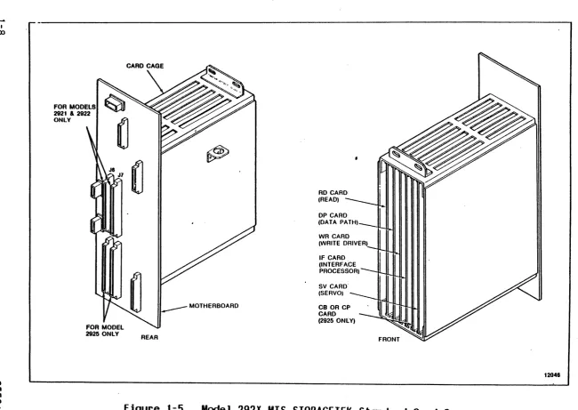
Mount) . . . . Model 292X MTS STORAGETEK Standard Card Cage
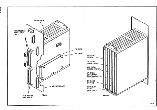
Model 292X MTS Industry Standard Card Cage Opera tor Pane 1, Ver t i ca 1 Mount . . . .
Operator Panel, Center of Gravity Mount . . . . . Tape Thread Path . . . .
Tape Path Components--Tape Not Loaded . . Start/Stop Mode Velocity Profile
Capstan Velocity Profile
Cables and Connectors . . . .
Interface Card Address, . . . . IF Card Terminator and Address Switch Locations. Vertical Mounting Installation
Vertical Mounting Dimension$ . . . ,. Sugges ted L i f t i ng Methods . . . ". . .
Center of Gravi ty Mount ing Dimensions . . . . Storagetek Standard Interface Cabling . . . . Storagetek Standard Interface Cable
Configuration . . . .
Industry Standard Interface Cabl ing . . . . MTS-User Interface Circuits . . . . Command Initiation, Operation, and Completion RDF or ROB Command TREQ, TRAK, and DATA Timing Write Commands Initiating TREQ/TRAK/DATA Timing
(Applies to First Byte of Data) . . . . WRT Command TREQ, TRAK and DATA Timing (Applies
to A 11 Subsequent Bytes of Da ta) . . . . . Standard Industry Interface Circuits .
Interface Timing For 50 IPS Start Stop, Case . . . . Interface Timing For 100 IPS Streaming,
Case . . . . 2925 MTS SCSI Bus Cabl ing . . . . Termination for Single-Ended Devices
Worst Worst
Termination for Differential Devices . . . . Phase Sequences without Arbitration . . . .
Phase Sequences with Arbitration
Page 1-2 1-3 1-4 1-5 1-9
1 - 10
Figure
7 - 1
7-2 7-3 7-4 7-5 8-1 8-2 8-3 8-4 8-5 8-6 8-7 8-8 8-9 8-10
8 - 11
9-1 9-2 9-3 9-4 10- 1 10-2 10-3 10-4 B-1 B-2 B-3
LIST OF ILLUSTRATIONS CONT
Title Interface Circuits . . . . Standard Interface Cabling MTS Interface Cabling.
Write Timing . . . Read Timing . . . .
MTS Block Diagram . . . . Interface/Microprocessor Block Diagram (IF
Card) . . . . . . . .
W r i t ePa t h Block D i ag ram (D P Car d ) . . . . Write Driver Block Diagram (WR Card) . . . . Read Block Diagram (RD Card)
Read Path Block Diagram (DP Card) . . . . Capstan Servo System Block Diagram . . . . Reel Servo System Block Diagram . . . . CB Card Block Diagram . . . .
CP Card Block Diagram . . . . Power System Block Diagram . . . . S ta tic and Dynami c Skew and Tu"rnaround Jump Capstan and Read/Write Head Alignment . . +Dif Analog Test Points . . . .
Bit Position Check . . . . 2920 MTS Deck (Front) . .
Read/Wr i te Head . . . . . Swing Arm Assemblies
Retractor Assembly PE Tape Format
GCR Tape Format . . . . GCR Data Block Format (Sheet 1 of 3).
Table
1 - 1
1-2 1-3 2-1 2-2 2-3 2-4 ')-~ " oJ
3-1 4-1 4-2
4-3
. 4-4 4-5 4-6 4-7 4-8 4-9 4-10 4- 11 4-12 4-13 4-14 4-15 4-16 5-1 5-2 5-3 5-4 5-5 5-6 5-7 5-8 5-9 5-10 5 - 11
5-12
6 - 1 .
6-2 6-3 6-4
LIST OF TABLES
Title
Performance Specifications . . . . Nominal Access Time From Stop (milliseconds) Power Requirements . . . . Generated InterblocK Gap Lengths (Inches) Selectable InterblocK Gaps
Reposition Times (Milliseconds) .
Nominal Reinstruct Times (Maximum Gap) Nominal Reinstruct Times (Minimum Gap) PK Board Wiring for Input Power . . . STK St~ndard Interface Output Lines . . STK Standard Interface Input Lines
MTS Address Line Decode . . . Command Select Decode . . . . Density Select Line Decode . Select Multiplex Decode . . .
Error Conditions Setting DATA CHK . . . . Error Multiplex Bus Decode for Functional Mode S tat us Line s Ass e r ted wit h . W T M C H K .. . . . REJECT Codes (Sheet 1 of 2) . . . . Status Line Assertion For DMS/NOP Command Sheet
1 of 2 . . . .
Status Line Assertion For Diagnostic Wrap Mode Speed And Gap Selection Decodes . . . . Diagnostics Extended Sense Bytes Summary . A-O Through C-F Sense Bytes Cross Reference . Operational Sense Bytes Summary . . . .
Industry Standard Interface Input Lines.
Industry Standard Interface Output Lines . . . . Interface Connector J6 Pin Functions . . . . Interface Connector J7 Pin Functions
MTS Address Line Decodes . . . . Functional Command Lines Decodes Diagnostic Command Lines Decodes
Reject Codes (Sheet 1 of 2) . . . .
Status Line Assertion for ISS Command . . . . Status Line Assertion For Diagnostic Wrap Mode Diagnostic Sense Bytes Summary . . . A-O Through C-F Sense Bytes Cross Reference . Single-Ended Pin Assignments . . . .
Differential Pin Assignments Informa t ion Transfer Phases . . . Messages Implemented by the MTS
Page 1-6 1-6 1-15 2-18 2-18 2-19 2-20 2-20 3-4 4-3 4-5 4~5 4-5 4-6 4-8 4-12 4-12 4-13 4-15 4-22 4-26 4-25 4-26 4-28 4-36 5-3 5-5 5-7 '5-9
5 - 11
Table 6-5 6-6 6-7 6-8 6-9 6-10 6-11 6-12 6-13 6-14 6-15 6-16 6-17 6-18 6-19 6-20 6-21. 7-1 7-2 7-3 7-4 7-5 7-6 7-7 7-8 7-9 7-10 9-1
1 1 - 1
11- 2
LIST OF TABLES CONT
Ti t le
Synchronous Data Transfer Request . . . . . S ta tus Bytes . . . . SCSI Commands . . . . Sense Key (OH-7H) Descriptions . . . . .
Sense Key (8H-FH) Descriptions . . . .
Request Sense Data (Bytes 0-19) . . . . Current Tape Drive Status (Bytes 20-27) . StorageTeK Cache Sense (Bytes 28-43)
StorageTeK Cache Sense (Bytes 44-59) .
StorageTeK Drive Sense (Bytes 60-115) . . . . Additional Sense Code Definitions (Sense Bytes
12 and 13) . . . . Read BlocK Limits Data . Inquiry Data . . . .
Mode Select Parameters Mode Sense Data . . . . . Diagnostic Parameter Data Diagnostic IDs
Interface Connectors . . . . Interface Lines.
MTS Address Lines . . . . . Command Lines . . . .
Interface Timing Data Transfer Timing
Ramp Times . . . . . . . . . . Speed/Gap Selection Decodes and Cache Mode Set
Decode . . . .
Reject Codes . . . . Read Controller Sense . . .
Capstan Alignment Instructions
Maintenance Routines Internal Diagnostics
Page 6-20 6-21 6-23 6-29 6-30 6-33 6-32 6-32 6-33 6-34 6-36 6-40 6-53 6-58 6-66 6-71 6-71 7-2 7-3 7-8 7-9 7-15 7-15 7-15 7-20 7-26 7-29 9-4
SEPARATOR SET PN 83464
THIS SEPARATOR SET CONTAINS 19 TABS TOTAL IN THE FOLLOWING ORDER:
MAINTENANCE MANUAL 1. INTRODUCTION 2. OPERA T f ON 3. INSTALLATIQN
4. STORAGETEK INTERFACE 5. INDUSTRY INTERFACE 6. SCS I INTERFACE 7. VS INTERFACE
8. FUNCTIONAL DESCRIPTION 9. MAINTENANCE
lQ REMOVAL/REPLACEMENT 11. DIAGNOSTICS
APPENDICES IPC
PN COMPATIBILITY MMLL
21/22/25 STD & 25 IND STD FCD 21/22 IND STD FCD
2925 SCSI FCD
Z
- f
;C
o
o
c:
C")
-I
CHAPTER 1
GENERAL INFORMATION
1.1 INTRODUCTION
Th is chapter is an in t roduc t i on to the S tor age Tech"no logy Corporation Model 292X .Magnetic Tape Subsystem (MTS). This chapter includes a general description of the physical and functional layout of the MTS and includes the MTS specifications. Two model types are avaiiabie, the 2921 and the 2922. The 2921 has a tape speed of 50 inches per second (ips) (127 cmps), start/stop. The 2922 has a tape speed of 50 ips (127 cmps) start/stop and 100 ips (254 cmps) streaming.
1.2 GENERAL DESCRIPTION
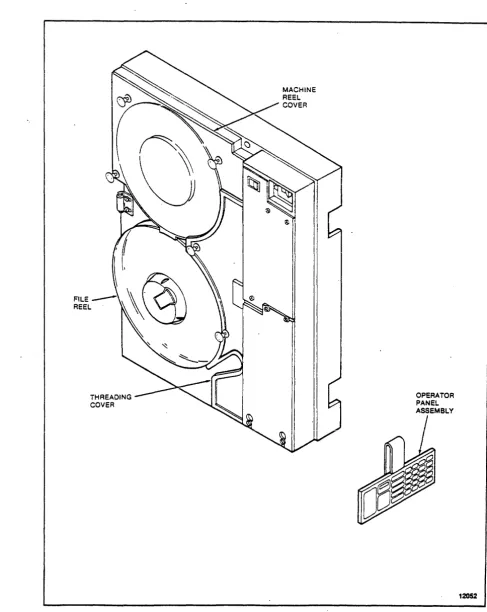
The MTS (Figures 1-1 through 1-4) is an integrated tape formatter/controller and half-inch (12.7 cm) tape drive packaged as a single self-contained unit (1x1). The MTS is a dual-density device capable of recording and reading ANSI compatible tapes in phase-encoded (PE) format at 1600 bits per inch (bpi) (63 bpmm) and group-coded recording (GCR) format at 6250 bpi (246 bpmm) at a tape speed of 50 (127 cmps) or 50/100 ips (127 cmps/254 cmps) , depending on the model.
The MTS is a low-cost, medium performance device intended for use in normal tape processing and/or disk off-loading. The device features automatic or "semiautomatic tape threading/loading of open reel sizes 7, 8.5, and 10.5 inches; tension arm tape buffering; microprocessor capstan servo and mic~oprocessor reel servo; and on-board diagnostics for functional verification and fau 1 t detect ion.
Data can be read when tape is moving either forward or backward but recording can be performed during forward tape motion only~
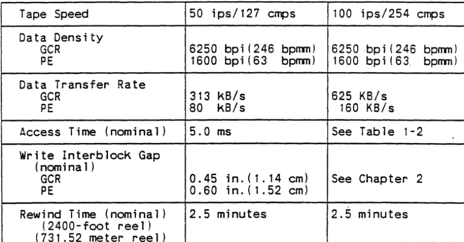
Performance specifications are shown in Table 1-1.
Nominal access time from stop is shown in Table 1-2 for the models 2921 and 2922. Access time is defined as the time from assertion of Busy on receipt of a read or write command at the interface to the time the beginning of the record is read from or written to tape. This is assuming tape starts from a stopped position, no turn-around condition is required, and tape is not positioned at BOT. See Chapter 2 for a detailed description of
MACHINE REEL COVER
FILE REEL
THREADING COVER
Figure 1-1. Model 292X MTS Front View (Vertical Mount)
,r
l
I: ,.FILE_~~\\&
REEL·
I'~
THREADING COVER
OPERATOR PANEL ASSEMBLY
/
12052
PLENUM
COVER
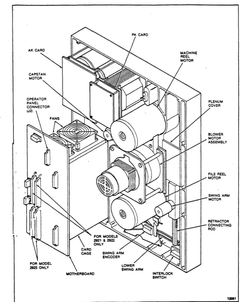
Figure 1-3. Model 292X MTS Rear View (Vertical Mount)
INTERLOCK SWITCH
PLENUM COVER
12053
Table 1-1. Performance Specifications
Tape Speed 50 ips/127 emps 100 ips/254 emps Data Density
GCR 6250 bpi (246 bpnm) 6250 ·bp i ( 246 bpnm) PE 1600 bpi(63 bpnm) 1600 bpi(63. bpnm) Data Transfer Rate
GCR 313 kB/s 625 KB/s
PE 80 kB/s 160 KB/s
Access Time (nom i na 1 ) 5.0 ms See Table 1-2 Write lnterblock Gap
(nomina 1 )
GCR 0.45 in.(1.14 em) See Chapter 2 PE 0.60 in.(1.52 em)
Rewind Time (nominal) 2.5 mjnutes 2.5 minutes (2400- foot ree 1 )
(731.52 meter reel)
Table 1-2. Nomina 1 Acces.s Time From Stop (mi 11 i seconds)
-2921/2922
MODE
IBG
READ WRITEStart/Stop 0.28 in./O.71 em 5.6 ms
--6250 bpi 0.30 in./0.76 em 6.0 ms-
-246 bpnm 0.45 in./l.14 em 9.0 ms 6.0 ms Start/Stop 0.50 in./l.27 em 5.6 ms-
-1600 bpi 0.60 in./l.52 em 7.6 ms 6.0 ms 63 bpmmStreaming 0.28
-
1 .2 in./ 12.0 ms --0.71-
3.05 em6250 bpi 0.30 in./0.76 em
-
-
12.5 ms 246 bpnmStreaming 0.5
-
1 .2 in./ 12.0 ms-
-1 .27-
3.05 em1.2. 1 Power Features
-Models ~921 and 2922 operate from either a 120 Vac, 60 Hz power source or a 220 Vac, 50 Hz power source. Chapter 8 provides a description of the power supply.
1.2.2 interface Features
Both models can be provided with either the StorageTek Standard Interface or the Industry Standard Interface (Pertec). The STK Standard Interface is described in Chapter 4 and the Industry Standard Interface is described in Chapter 5.
1.2.3 Mounting Options
Both models are available with either gravity (horizontal) mounting options.
installation.
1.2.4 Diagnostic Features
vertical or center of Chapter 3 describes each
The internal diagnostics programs are capable of detecting fault conditions in the tape subsystem and isolating fai.lures within a' specific number of field replaceable units (FRUs). A unique package is required for machines using the Industry Standard Interface. Optional programs are available on floppy diskettes to provide 292X interface verification and limited online exercising. See Chapter 11 for details.
1.2.5 Electronics
The electronics of the MTS are located on five plug-in printed circuit cards located in a card cage below the operator panel.
The Industry Standard Interface requires two additional cards: PA and PB adaptor cards. These cards are identified in Figures 1-5 and 1-6. In addition, there is an operator panel circuit card
(KK)
and three power supply circuit cards: theAK
andNK
I 00
lO
U1
FOR MODELS
2921 & 2922
ONLY
REAR
~ ~
RD CARD (READ)
DP CARD (DATA PATH)
IF CARD (INTERFACE PROCESSOR)
SV CARD' (SERVO)
CB OR CP CARD (2925 ONLY)
CD U1 U1 "-l
FOR MODELS 2921 & 2922 ONLY
FOR MODEL 2925 ONLY
CARD CAGE
REAR
PB CARD
PA CARD
DP CARD (DATA PATH)
IF CARD (INTERFACE PROCESSOR)
-SV CARD (SERVO)
CB OR CP CARD (2925 ONLY)
1.3 SPECIFICATIONS
Physical, environmental and power requirements for the MTS are as follows:
1.3.1 Physical Dimensions
The nominal outside dimensions of the MTS are: Height
Width Depth
Project ion Weight
24.5 inches (62.2 cm) 19.0 inches (48.3 cm) 16.0 inches (40.6 em)
4.8 inches (12.2 em) from RETMA
125 pounds (57 kg) mounting surface 1.3.2 Environmental Requirements
Temperature (Ambient Room Air): Opt imum
Operating Non-Operating Relative Humidity:
Opt imum Operating Storage Shipping
+ 16°C to +22°C (+BOo F to +72° F) +16°C to +31°C (+600F to +900F)
-40°C to +70 oC (-40°F to +158°F)
37% to 42%, noncondensing 20% to 80%, noncondensing 10% to 90%, noncondensing Any, noncondensing
The storage environment must not exist outside the limits of the operating environment for a period longer than six months.
The MTS must not be subjected to a temperature change greater than
aoc
(15°F) per hour.Altitude:
Operating Up to 1830 meters .(6,000 feet) standard Up to 3050 meters (10,000 feet) with
'1.3.3 Power Requirements
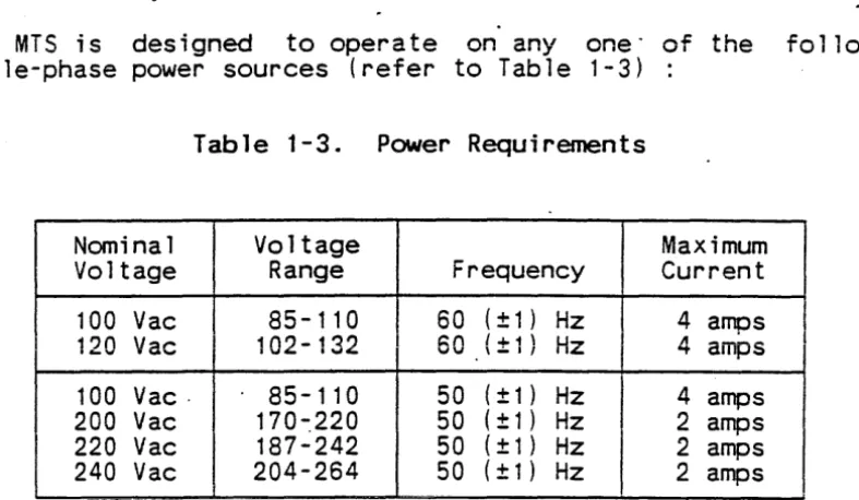
The MTS is designed to operate on anyone" of the following single-phase power sources (refer to Table 1-3)
Table 1-3. Power Requirements
Nominal Voltage Maximum Vo 1 tage Range Frequency Current 100 Vac 85-110 60 (± 1 ) Hz 4 amps _'" ac • ",400
-
'..,4 IJ'IJ \ - I I IZ "'t ampsl'Jn V
100 Vac· 85-110 50 (± 1 ) Hz 4 amps 200 Vac 170-:220 50 ( ± 1 ) Hz 2 amps
220 Vac 187-242 50 ( ± 1 ) Hz 2 amps
240 Vac 204-264 50 ( ± 1 ) Hz 2 amps
The MTS is assembled and shipped to operate from either a 120 Vac, 60 Hz power source or a 220 Vac,· 50 Hz power source. Conversidn to other power sources requires changes to the primary -side wiring of the MTS input power transformer (refer
to
chapterSEPARATOR SET PN 83464
THIS SEPARATOR SET CONTAINS 19 TABS TOTAL IN THE FOLLOWING ORDER:
MAINTENANCE MANUAL 1. INTRODUCTION 2. OPERA T I ON 3. INSTALLATION
4. STORAGETEK INTERFACE 5. INDUSTRY INTERFACE 6. SCSI INTERFACE 7. VS INTERFACE
8. FUNCTIONAL DESCR!PTION 9. MAINTENANCE
10. REMOVAL/REPLACEMENT 11. DIAGNOSTICS
APPENDICES IPC
PN COMPATIBILITY MMLL
21/22/25 STD & 25 IND STD FeD
21/22 IND STD FCD
2925 SCS I FCD
N
o
"
r"'I
:c
>
-f
CHAPTER 2
OPERATION
2. 1 INTRODUCTION
This chapter describes the operator panel functions and status indicators, the common MTS operating procedures, and the required operator maintenance.
2.2 POVVER ON/OFF SVVITCH
The Power On/Off switch is used to power up or power down the MTS. When powered up, the MTS initializes and invokes a series of power-up diagnostics.
2.3 DISPLAY
The operator panel contains a four-character display. When the MTS is in Online Status, the display is blank. During machine check conditions, the display contains a three-digit fault cod~.
When "the MTS is offline and at idle, the display contains four dashes indicating that the MTS is ready to accept diagnostic commands. When a key is" depressed, all segments of the display are lit to indicate that the key has been recognized and accepted. When pressure is removed from the key, the display returns to its previous state.
Throughout this manual, display conditions are shown enclosed within parentheses. To summarize the display conditions and their meanings:
( )
(---- )
(@n ) (@nn ) ( nn) (nnnn)
( ??) (????)
( nnn)
On 1 i ne
Offline, panel idle, test successfully completed Executing maintenance routine
Executing diagnostic routine
Displaying data (flashing if from probe) Displaying address
Request for data or test 1D input Request for address input
Fault code (refer to Fault Code Dictionary PN 97712 or 87004)
2.4 OPERATOR FUNCTIONS AREA
The operator functions area of the operator panel and 2-2) provides status indicators and a keypad control of the normal functions of the MTS.
DISPLAY
----OPERATOR FUNCTIONS
-
L...-Power
IITlI
On Off I 0r"--I
I
I Ready I
I Select I
I EOT/BOT I
I On Une I
I Mach Chk I
I File Prot I
I Sys Sel I
I 6250 I
I 1800 I
I
Density 111111/I
RewlUn~ 1111111
-I
Ruet 1111111I
Load Rew 1111111I
On U... 1111111~
~
L..--II
II
0~11e-~
(/)
0
0
~~DD
Addr Add'r;;JODD
~DDD
~DDD
[;]
[;]
I
I
I
DIAGNOSTIC KEYPAD
Figure 2-1. Operator Panel, Vertical Mount
CIRCUIT BREAKER
C8:!REAOY
~(
REW UNLO)
(~6~R O)(~~ 1)c==J~C8J SELECT
(
RESET] [[]c=Jc=JCJ
C8J EOT/BOT
(
LOAD REW)
Wo~8c=JCJc]
C8J ON LINE [81 SYS SEL
C8J MACH CHK [816250
(
ON LINE)~c=3CJc]
l
C8:l FILE PROT)l
C8:l1600 r ) (ENTER )[1(
) (CLEAR )
) l
DENSITY12039
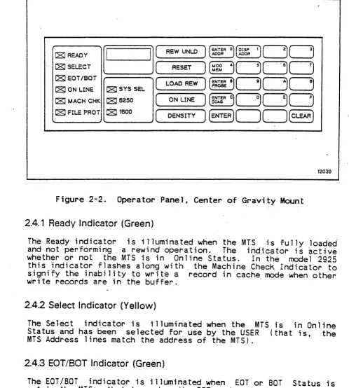
Figure 2-2. Operator Panel, Center of Gravity Mount 2.4.1 Ready Indicator (Green)
The Ready indicator is illuminated when the MTS is fully loaded-and not performing a rewind operation. The indicator is active whether or not the MTS is in Online Status. In the model 2925
this indicator flashes along with the Machine Check Indicator to signify the inability to write a record in cache mode when other write records_are in the buffer.
2.4.2 Select Indicator (Yellow)
The Select indicator is illuminated when the MTS is in Online Status and has been selected for use by the USER (that is, the MTS Address lines match the address of the MTS).
2.4.3 EOT/BOT Indicator (Green)
2.4.4 On Line Indicator (Green)
The On Line indicator is illuminated when Online Status is set in the MTS; that is, when the MTS is avai lable to the user.
2.4.5 Machine Check Indicator (Red)
The Machine Check (MACH CHK) indicator flashes to signal either a load check, which may be operator correctable, or to signal a malfunction of the MTS that requires service. A fault code of three characters is posted in the display. In model 2925 this indicator flashes along with the Ready Indicator to signify the inability to write a record while in cache made when other write records are in the buffer.
2.4.6 File Protect Indicator (Red)
The File Protect (FILE PROT) indicator is illuminated when tape is loaded and a write enable ring is not in place on the file reel. Write operations can not be performed when this indicator is illuminated.
2.4.7 System Select.! 1600/6250 Indicators (Yellow)
The System Select (SYS SEl), 1600, and 6250 indicators ~re used to show the current operating density of the MiS. The operator may select a density mode using the Density Select key when the MTS is either not loaded or loaded and positioned at BOT. The selected mode determines the density in which a tape is to be
written. .
Illumination of the 1600 indicator alone indicates that the tape wi11 be written in 1600 bpi density (PE format). Illumination of the 6250 indicator alone indicates that the tape will be written in 6250 bpi density (GCR format). Illumination of the System Select indicator in combination with illumination of the 1600 indicator indicates that the recording density is to be selected by the CPU. On power up, the MTS will indicate System Select and
1600.
A read operation will be in the correct density regardless of the initial setting of the indicators. When the density of the tape being read has been determined, the corresponding indicator (1600 or 6250) is illuminated.
2.4.8 Density Select Key
Successive actuations of the key causes the MTS to cycle through the possible density modes. Upon power up, the MTS will be set to SYS SEL/1600 mode. Pressing DENSITY causes the MTS to go to 1600 bpi density. A second press causes the MTS to go to 6250 bpi density. Entering DENSITY a third time returns the MiS to SYS
SEL/1600 mode.
Execution of a diagnostic routine may cause the density status of the MTS to change. A tape load operation will reinitialize the MTS to SYS SEL/1600 mode.
2.4.9 Rewind/Unload Key
The Rewind/Unload (REW/UNLD) key is used to unload tape. If tape is not at BOT when the key is pressed, a high speed rewind to BOT is initiated, the swing arms are retracted, and tape is unloaded from the tape path. Select and Ready Status are reset by this key. This key is not accepted if the MTS is in Online Status. 2.4.10 Reset Key
The Reset key is used to generate a subsystem reset. Pressing this key resets Select, puts the MTS in Offline Status, terminates any operation and tape motion that is in progress, cleats ~ny·machine check condition, and returns the display to
idle (---- ),.
2.4.11 Load/Rewind Key
The Load/Rewind (LOAD/REW) key serves a dual p~rpose. If tape is not loaded, this key is used to load tape and position tape at BOT. If tape is loaded, this key causes tape to be rewound and positioned at BOT. This key is disabled if the MTS is in Online Status.
2.4.12 On Line Key
The On Line key is used to set the MTS to Online Status. Setting the MTS to online status will cause all presently on-going MTS operations to cease. Online status disables the Rewind/Unload and Load/Rewind keys. The online condition is reset by the reset key. 2.5 DIAGNOSTIC KEYPAD
memory space location (probe). The operations available are dependent upon the status of the MTS and the current display contents. The keypad will not respond when the MTS is in Online Status or if a machine check is present (nnn). While idle (----) or er~or ( nnn) is present, all panel functions are available. During the execution of a maintenance program or diagnostic routine (@n ) or (@nn ), only memory read functions are available (Enter Address, Enter Probe, and Display Address). The Reset key serves to return the panel to an idle condition
(
----
).
The main function of each key on the keypad is marked on the key. Some keys have alternate' control functions. The protocol for using the diagnostic keypad consists of entering a control function and then entering data characters as required. The display contains input and output symbols appropriate to the
function in process.
The diagnostic keypad is also used to enter data characters. The data c~aracter associated with a given key appears in its upper right corner.
2.5.1 Enter Address Key
The Enter Address key is used to select an address from which data display is desired. Pressing the Enter Address <ENTER ADDR> key a110ws the entry of a hexadecimal number representing a
location within the memory of the MTS controller. The display prompts for the entry with four question marks (????) until the first entry is made. The first entry then appears right-justified in the display with subsequent entries producing a shift left on the display. Any number of entries may be made. If the target address desired is the same as that most recently referenced, a press of the Enter key directly following the prompt display is sufficient.
When the desired address appears on the display, the Enter key terminates address entry and causes the byte at that address to be displayed as two hexadecimal digits, right-justified. At this time each actuation of the Enter key displays the contents of the next memory location.
2.5.2 Display Address Key
The address last displayed is stored so that normal machine operation will not destroy it. The Display Address key may then be used at any time (for instance; following a diagnostic routine) and the Enter key may be pressed to recall a frequent memory location.
If the Display Address key is pressed following subsystem power up and before the Enter Address function is used, memory location 0000 is displayed.
2.5.3 Modify Memory Key
The Modify Memory <MOO MEM> key is used to modify a writeable "Emory location within the MTS controller. This Key is recognized only while data from the target location (from an <ENTER ADDR> or <DISP AOPR> key sequence) is being displayed. No memory modification is allowed while a diagnostic routine is executing. If this Key is pressed at. any other time, there wi 11 be no response,.
CAUTION
-If the memory is modified, MTS operation is not guaranteed.
Following the actuation of' the Modify Memory Key, the display prompts for a byte value input (two hexadecimal entries) by displaying two question marks ( '??). The operator may now use as many keystrokes as necessary to produce the required data in the display. Each entry results in a shift left of the two digits on
the right (the two digits on the left remain blank).
When the data desired to be written is being displayed, pressing the Enter Key causes the data to be stored in the current memory location. (If the location being written is a read-only address~
there will be no effect on that location.) 2.5.4 Enter Probe Key
The Enter Probe <ENTER PROBE> key is used to cause a constantly updated display of a particular controller memory space location. The updating is indicated by a rapidly flashing byte on the display .
. Following the actuation of the Enter Probe key, the display prompts for address input by displaying four question marks
display flashes the byte continuously at about second. "The system may be brought back to idle the Clear or Reset key.
2.5.5 Enter Diagnostic Key
ten times per by using either
The Enter Diagnostic <ENTER DIAG> key is used to initiate the entry of subsystem self-contained diagnostic routine numbers. After pressing the Enter Diagnostic key, the display prompts for the entry of a two-digit hexadecimal routine identification by displaying two question marks ( ??). The operator may now use as many keystrokes as necessary to produce the required 10 in the display. Each entry results in a shift left of the two digits on
the right (the two digits on the left remain blank).
When the desired routine number appears in the display, pressing the Enter key results in the attempted execution of that routine. The 10 is displayed while the routine is being executed. If the routine is not successful, fault codes are displayed as three hexadecimal digits. If the routine is successful, completion is
indicated by the idle display (----).
A routine in progress may be terminated by pressing the Reset key.
2.5.6 Enter Key
The_Enter <ENTER> key is specific in nature and is described in t he sec t ions above for all sequence"s. For mos t cases t his key serves to delimit address and data entries and initiates the performance of a requested function.
2.6.7 Clear Key
The Clear <CLEAR> key is used to clear the last data and/or address entry in the display and return to the prompt mode (question marks in the display) of the last function attempted. If the MTS is currently in a prompt mode (no entry has been made), the MTS returns to an idle state and awaits a function request. If a diagnostic routine is being executed, its 10 is again displayed.
2.6 TAPE THREADING OPERATIONS
2.6.1 Automatic Thread/Load--Vertical Mount
The automatic thread/load is the normal procedure for vertically mounted machines.
1 . Power up the' MTS, if necessary; the swi ng arms automa t i ca lly extend and then retract. Ensure the machine reel cover and
the thread cover are closed.
2. Unlatch the file hub locking lever. Place the reel of tape
3.
on the file reel hub, then relatch the lever. Make certain that the reel is secure.
Press LOAD/REWIND. sensors are enabled, on.
The vacuum blower
and power the motor turns r ee 1 iliC) tor s
on, the is turned The MTS initially assumes that the tape leader is positioned at the entrance of the tape threading path and rotates clockwise to slip the tape leader into the path. If tape is not sensed at the EDT/BOT sensor within a given amount of Jime, the file reel reverses and attempts to position the tape leader using the leader sensor. If the leader cannot be sensed, it is assumed that the leader is stucK to the tape reel with static and the file reel. is rotated rapidly to try to break the static. When the leader is sensed, it is positioned at the entrance of the .tape threading path.
Vacu'um created by the blower motor pulls' the tape up the tape threading path. The tape is sensed at the EDT/BOT sensor as Tape Present. When the tape has wrapped the machine reel hub, it is sensed as Tape Attached and the blower motor turns off. If any of these steps fails to occur in the prescribed time, a mark is counted against the load. If three marks are counted, the load has been unsuccessful and a fault code is posted in the display.
When Tape Attached is sensed, the tape is moved forward until the beginning-of-tape (SOT) marKer is found. Tape continues to move forward a few feet and stops. The swing arms are lowered into their normal operating area.
Tape is rewound to BOT. When BOT is sensed and tape is stopped, the file reel is moved such that the MTS logic can determine file reel size. Tape then moves forward past BOT and a series of start/stop operations is run forward and then repeated backward. These start/stops allow the adaptive features of the capstan control algorithms to initialize for the current ~ape.
4. Pressing ON LINE after the Ready indicator is lit enables the MTS to accept commands from the user.
2.6.2 Semiautomatic Thread/Load-Vertical Mount
If the tape does not load ·successfully during automatic thread/load, the semiautomatic thread/load procedure can be used. 1. Power up the MTS and load the file reel onto the hUb.
2. Press the Load/Rewind button twice,
interval between presses. with a four second 3. Manually and slowly rotate the file reel clockwise to allow the tape leader to drop into the tape path until the file motor moves on its own.
2.6.3 Semiautomatic Thread/Load--Center of Gravity Mount
The semiautomatic thread/load is the normal procedure for center of gravity mounted machines.
1. Power up the MTS and load the file reel onto the hub. 2. Press the Load/Rewind button once.
3. Manually and slowly rotate the file reel clockwise and pull the tape leader into the tape path cavity.
4. Continue to rotate the file reel until enough tape leader is released into the tape path for the file motor to move on its own.
2.6.4 Manual Thread/Load--Vertical or Center of Gravity Mount
If the blower motor is not operating, tape must be loaded manually. Refer to 2-3
1. Power up the MTS and load the file reel onto the hub. 2. Open the thread cover and remove the machine reel cover.
3. Pull the tape leader under the lower swing arm roller, through the tape path, over the capstan wheel, under the upper swing arm roller and ~ver the machine reel.
5. Press the Load/Rewind button.-2.6.5 Midtape Load, EOT Area
If a load is required when tMe- tape is in the EDT area (after POWER DOWN or LOOP OUT), a load problem may occur. A forward search for SOT will be initiated and may cause tape to be pulled off the file reel. To avoid this, use the following procedure:
1. Power up the machine if necessary (allow diagnostics to comp lete) .
2. Press' UNLOAD' .
3. Allow the tape to rewind onto the file reel for about 10 seconds.
4. Press 'RESET' to halt the unload. 5. Press 'LOAD' for a midtape load.
•
2.6.6 Rewind
1. If the MTS is in Online Status, press RESET.
2. Press LOAD/REWIND. -Tape re~;nds at high speed, passes BOT, stops, moves forward to the BOT marker, and stops in Ready Status.
2.6.7 Unload
1. If the MTS is in Online Status, press RESET.
2. Press REWIND/UNLOAD. I f tape is posi t ioned off BOT, it wi 11 rewind at high speed, pass BOT, stop, and move forward to the BOT marker. With tape at BOT, the swing arms retract, tape ;s unloaded onto the file reel, and power for the reel motors is turned off.
2.7 OPERATOR MAINTENANCE
Because cleanliness is crucial to successful magnetic tape operations, there are several operator cleaning procedures which should be performed daily or ~fter each eight-hour shift under normal operating conditions.
TAPE PATH
Figure 2-3. Tape Thread Path
CAPSTAN WHEEL
READIWRITE HEAD
CLEANER BLOCK
cloth or foam-tipped swab. Refer to Appendix B for the part number of the cleaning supplies. After applying cleaner~ allow a few minutes for excess,fluid to evaporate before mounting a tape. 2.7.1 Read/vVrite Head and Tape Cieaner Biock
WARNING
The tape cleaner blade is sharp. Use extreme care when handling the tape cleaner block.
Clean the read/write head and the tape cieaner· blocK using a lint-free cloth'moistened with Hub and Transport Cleaner Fluid. Make certain the head and cleaner block are free of oxide deposits. Use foam-tipped swabs to clean the cleaner block.
2.7.2 EDT/BOT and Leader Sensors
Clean the EaT/BOT and leader sensor windows using a foam-tipped swab moistened with Hub and Transport Cleaner Fluid. Allow time for complete drying and remove any residue with a dry swab.
2.7.3 Tape Guides, Rollers, and Swing Arms
Clean the two tape guides, the three fixed rollers, and the four swing arm rollers using a lint-free cloth moistened with Hub and Transport Cleaner Fluid. To reach otherwise inaccessible areas, foam-tipped swabs may pe used. If necessary, the edge of a data processing card' may be used to clean the flange corners of the guides.
2.7.4 Capstan
Clean the capstan using a lint-free cloth wrapped around the index finger and moistened with Hub and Transport Cleaner Fluid.
CAUTION
Do not touch the outer, tape-contacting surface of the capstan with the bare hand as the surface is sensitive to contamination. Always use a cloth when handling the capstan and grip only the hub of
the capstan.
CAPSTAN WHEEL
UPPER TAPE GUIDE
READIWRITE HEAD
TAPE CLEANER BLOCK
LOWER TAPE GUIDE
EOT/BOT SENSOR THREADING DIVERTER
revolutions is sufficient. Wipe the capstan with a dry, lint-free cloth to remove excess cleaner fluid.
2.7.5 File Reel Hub
Clean the expansion surface of the file reel nuo using a lint-free cloth moistened with Hub and Transport Cleaner Fluid. 2.8 TAPE MOTION CHARACTERISTICS
The 2921 operates at a nominal tape velocity of 50 inches per second (ips) in the start/stop mode.
The 2922 operates at a nominal tape velocity of 50 ips in the start/stop mode and 100 ips in the streaming mode.
The 2925 with Cache Buffer operates at a nominal tape velocity of 100 ips in the streaming mode. Although the 2925 is capable of 50 ips operation, the 50 ips mode is generally not used.
NOTE
The MTS defaults to the velocity switch setting at power on.
The effects 'of velocty profiles and' gap sizes in tahe -2925 are generally masked from the host interface as a result of the cache buffer. The buffered MTS includes both the start/stop mode and streaming mode as described in the following paragraphs. The start/stop and streaming modes are apparent to the host interface when the MTS is operated in the long-record (non-buffered) mode. 2.8.1 Start/Stop Mode
In start/stop mode the tape travels a certain distance after the read head reaches the end of a record before the tape begins to decelerate. This "holdover" travel can be useful at 1600 bits per inch (bpi) density because it gives the maximum "reinstruct window" during which time the MTS can be given a new corrmand and continue traveling at full speed. The nominal holdover distances at 1600 bpi are 0.25 inch for a read and 0.19 inch for a write, which translates into reinstruct windows of 4.0 milliseconds and 2.8 milliseconds, respectively.
If the MTS is reinstructed during the deceleration ramp in either density, tape need not come to a complete stop as shown in Figure 2-5. Refer to Section 2.9 for further information on lBGs.
0.43 IN. GAP 0.37 IN.
I
GAP
~
IPS1 :;.---1 _
o IPS _ _ _ _
\L_'_fi_'. ____ _
t---r--s.O MILLISECONDS
NOMINAL
Figure 2-5. Start/Stop Mode Velocity Profile Section 2.9 for further information on lBGs.
12040
The nominal start or stop time at 50 ips is 5.0 milliseconds. The dotted area in Figure 2-5 shows, however, that the tape need not come to a complete stop if it is reinstructed early enough. The start and stop times are then less than 5.0 milliseconds. If the tape does come to a complete stop, it can be restarted without further delays.
2.8.2 Streaming Mode
In the 100 ips streaming mode without cache buffer, the tape does not stop at all if reinstructed promptly enough. However, if the end of the interblock gap is reached and a new command has not been received, a repositioning cycle is performed. Repositioning is accomplished relatively quickly by using the capstan to stop the tape and back it up to the point where it is ready for the next instruction. Meanwhile, the machine