TeleVideo
a
Display
Terminal
QPerOtor's Manual
(~~
-,;:.~-•....
, .....
-..
:.~ .~.
...TELEVIDEO~9220
VIDEO DISPLAY TERMINAL OPERATOR'S MANUAL
TeleVideo Document 131977-00 15 December 1985
Copyright
Copyright (c) 1985 by TeleVideo Systems, Inc. All rights
reserved. No part of this publication may be reproduced,
transmitted, transcribed, stored in a retrieval system, or translated into any language or computer language, in any form or by any means, electronic, mechanical, magnetic, optical, chemical, manual, or otherwise, without the prior written permission of TeleVideo Systems, Inc., 1170 Morse Ave., P.O.
Box 3568, Sunnlyvale, California 94088-3568.
Disclaimer
.TeleVideo Systems, Inc. makes no representations or warranties
with respect to this manual. Further, TeleVideo Systems, Inc.
reserves the right to make changes in the specifications of the product described within this manual at any time without notice and without obligation of TeleVideo Systems, Inc. to notify any person of such revision or changes.
FCC Class A Warning
This peripheral equipment generates, uses, and can radiate
radio frequency energy. If not installed and used in
accordance with the instruction manual, i t may cause
interference with radio emissions. This peripheral equipment
has been tested and found to comply with the limits for a
Class A computing dev ice, pursuant to Subpart .:J of Part 15 of
FCC Rules, which are designed to provide reasonable protection against radio frequency interference when operated in a
commercial environment. Operation of this equipment in a
residential area is likely to cause interference, in which case the user at his own risk and expense wi 11 be required to
correct the interference. The use of nonshielded I/O cables
may not guarantee compliance w:th FCC RFI limits.
TeleVideo is a registered trademark of TeleVideo Systems, Inc. DECT.M·and VTT.M·-are trademarks of Digital Equipment Corporation. TektronixT.M·and Plot 10T.M·are trademarks of Tektronix, Inc.
TeleVideo Systems, Inc., 1170 Horse Ave" P.O. Box 3568,
'fABLE OF CON'l'EN'l'S
INTRODUCTION Meet the 9220
Terminal Features Graphics Option Using This Manual
Attention, Please
1. INSTALLATION 1
Unpacking 1
Inspecting the Terminal 1
Selecting a Site 1
Installation Steps 3
Connecting the Keyboard 4
Seiore You Connect the Terminal 4
Connecting the Terminal With an R~-232C Interface 4
Connecting the Terminal With a current Loop Interface 5
Connecting the Terminal to a Printer 6
Plugging In and Turning On the Terminal 7
Installation Summ~ry 8
2. SETTING OPERATING VALUES 9
How Set Up Works 9
Set Up Procedure 9
Set Up Categories 11
The Set Up Screens 12
3. OPERATING THE 9220 33
The Keyboard 33
Character Keys 34
Editing Keys 35
Special Keys 37
Function Keys 40
Controlling the Terminal From the Keyboard 42
Communication Modes 42
Editing and Sending Data 43
R~setting the Term~nal 43
Composing Characters 44
Screen Appearance 50
The Cursor 50
Screen-Saver Feature 50
The Status Line 50
4. TROUBLESHOOTING
Troubleshooting Procedures Troubleshooting Table Testing the Terminal Checking the Line Fuse If You Need Assistance
Applications Support Technical Support Service Under warranty Shipping the Terminal
5. PROGRAMMING THE 9220
Entering Commands
Sending Commands From the Host Entering Commands From the Keyboard Command Descriptions
Terminal Programming Modes Terminal Emulation Modes
Setting the· Control Transmission Mode Setting the Programming Mode
Operating Mode Commands ANSI Set/Reset Mode Private Set/Reset Mode Resetting Operating Values
Soft Reset Power-On Reset
Factory Default Reset Keyboard and Bell
Cursor Key Mode Keypad Mode
Disabling the Keyboard Disabling Set Up
Keyclick
Auto Repe.at Mode Sounding the Bell Screen Appearance
Screen Saver
Screen Visibility Mode Screen Background
Character Intensity Mode Visual Attributes
Line Attributes Columns Per Line
Cursor Visibility Mode Cursor Attributes
Displaying the Status Line
Programming the Status Indicators
Character Sets
Hard Character Sets
User-Definable Character Sets Creating a Soft Character Set Designating Character Sets Mapping Character Sets Mapping a Sinqle Character Scrolling
Controlling the Rate of Scrolling Defining a Scrolling Reqion
Origin Mode Cursor Control
New Line Mode
Scrolling Cursor Movement Basic Cursor Movement Cursor Addressing Cursor HOllie
Cursor Description Tabs
Changing the Tab Stops
Moving the Cursor to a Tab Stop Editing Modes
~utowrap t-Iode
Insert/Replace Mode Editing Data
Insert a Character Delete Character Insert a Line Delete a Line Erasing Characters Erasing a Line Erase Screen Erase in Field
Setting the Selective Erase Attribute Selective Erasing
Communicating With a Computer Setting the Communication Mode Local Echo Mode
Sending Transmit Control Characters Sending Screen Data in BlocK Mode Printing
Buffered Print Mode
Bidirectional Print Modes Auto Line Print Mode Print Region Mode Line and Page Print
Page print Terminator Mode
The Function Keys
Default Function Key Codes Proqramming the Function Keys Tests and Reports
Displaying Test Patterns The Self Tests
The AnswerbacK Message Terminal Status Report Cursor Position Report Printer Port Status Report User-Defined Keys Status Report Device Attribute Requests
The Terminal 10
APPENDICES
A Specifications
B Statement of Limited Warranty
C ASCII Code Tables
D Character Sets
E Character Set Keyboards
F
Con~rol Codes and Cscbpe SequencesG Key CodEs
H Current Loop Configuration T~bles
GLOSSARY
INDEX
QUICK REFERENCE GUIDE
vi
105 105 106 108 108 108 108 109 109 109 109 110 110
A-l A-4 A-5 A-9 A-16 A-24 A-30
1!\-32
0-1
X-l
LIST OF TABLES 1-1 1-2 1-3 :2-1 2-2 2-3 2-4 2-5 2-6 2-7 2-8 2-9 3-1 3-2 3-3 3-4 3-5 4-1 5-1 5-2 5-3 5-4 5-5 5-6 5-7 5-8 5-9 C-l C-2 C-3 C-4 0-1 0-2 E-l E-2 E-3 E-4 E-5 E.-6 E-7 E-8 E-9 E-10 E-ll E-12
RS-232C Connector Pin Assignments
20 mA Current Loop Connector Pin Assign~ents
25-Pin RS-232C Printer (DCE) Interface Connector Assignments
Set Up Categories
Set-Up Directory Fields Display Set-Up Fields General Set-Up Fields
Communications Set-Up Fields Printer Set-Up Fields
Keyboard Set-Up Fields Tab Set-Up Fields TVS9220 Set-Up Fields Editing Keys
Special Keys Function Keys
Character Composing Sequences Status Line Messages
Troubleshooting Terminal Problems Command Elements
9220 Emulation Mode Features
Terminal Operation in 7- and 8-Bit Modes Effect of Soft Reset
Cursor Key Codes
Numeric and Application Mode Key Codes Communication Modes
Print Modei and Comm~nds
Unshifted Function Key Codes ASCII Code Chart
Supplemental Character Code Chart Displayed ASCII Control Characters
Displayed Supplemental Control Characters ASCII, Supplemental and Special Graphics Characters
Soft Font Character Positions North American Keyboard
United Kingdom Keyboard Flemish Keyboard
Canadian (French) Keyboard Danish Keyboard
Finnish Keyboard
German/Austrian Keyboard Dutch Keyboard
Italian Keyboard
Swiss (French) Keyboard Swiss (German) Keyboard SwediSh Keyboard
LIST OP TABLES Continued
:t-13 Norwegian Keyboard A-22
E-14 French/Belgian Keyboard A-22
£-15 Spanish Keyboard A-23
F-1 Control Codes A-24
F-2 Escape Sequences A-25
F-3 CSI Sequences A-26
F-4 ANSI Set/Reset Operating Modes A-28
F-5 Private Set/Reset Operat.ing Modes A-28
F-6 VT52 Mode Commands A-29
0-1 Editing Key Codes A-30
0-2 PF Key Codes A-30
0-3 Application Mode Cursor Key Codes A-30
0-4 Application Mode Numeric Keypad Codes A-31
0-5 VT220 and 9220 Function Key Codes A-31
H-1 Active Transmit and Receive A-32
H-2 Active Transmit and Passive Receive, -20 IIA A-32
From Host
H-3 Active Transmit and Passive Receive, +20 mA A-33
FrOLl Host
H-4 Passive Transmit and Receive, +20 mA From Host A-33
H-5 Passive Transmit and Receive, -20 mA From Host A-34
H-6 Passive Transmit and Active Receive A-34
LIST OF FIGURES 1-1 1-2 1-3 1-4 1-5 1-6 2-1 2-2 2-3 2-4 2-5 2-6 2-7 2-8 3-1 3-2 3-3 3-4 3-5 3-6 4-1 4-2 4-3 5-1 5-2 5-3 5-4 5-5 5-6 5-7
Comfortable Terminal Lighting Ideal Terminal Placement 9220 Terminal, Front View 9220 Terminal, Back View
Pin Numbers (25-Pin RS-232C Connector)
Pin Numbers (a-Pin 20 rnA Connector)
Set-Up Directory Display Set-Up Screen General Set-Up Screen
Communications Set-Up Screen Printer Set-Up Screen
Keyboard Set-Up Screen Tab Set-Up Screen TVS9220 Screen 9220 Keyboard Character Keys Editing Keys Special Keys Function Keys
Data Sent by the Send Key
I~cction of the Line Fuse Good Fuse
Burned-Out Fuse Line Attributes
Special and Multinational Characters Greek Sigma Character
Scrolling Region of Double-Height Lines Effect of Origin Mode on Screen Line Numbers Data Flow in Communication Modes
Print Modes
UlTRODUC"l' I ON
MEET THE 9220
TeleVideo designed the 9220 with high priority on user
convenience and productivity. Its low-profile keyboard and
tilt-and-swivel monitor design make it truly user adaptable.
The 9220 incorporates the latest advances in human-factors engineering with a full spectrum of operating features and kNSI X3.64-compatible codes.
Terminal Features
Features of the 9220 include:
VT220, VT100, and VTS2 programming compatibility Improved VT220-style keyboard
30 programmable function keys Full 8-bit data word capacity
Graphics, multinational and user-definable character sets 16 displayed language sets, set-up selectable
Optional foreign-lanquage keycap sets
Keybo~rd supplemental character composition
Improved RS-232C/423 main port Current loop interface
Easy-to-use set up screens
Amber screen: no-cost green option
Graphics Option
TeleVideo offers an optional graphics board kit and mouse that let you create business, engineering, and scientific graphics using Tektronix Plot lO-compatible software or programs you
wr i te your se 1 f.
Introduct ion
USING THIS MABUAL
Chapter 1 contains step-by-step instructions showinq how to install the terminal.
Selecting the terminal's operating characteristics and
configuring it to communicate with your computer and printer are covered in Chapter 2.
Chapter 3 describes the keys and terminal operations controlled from the keyboard.
Chapter 4 has a troubleshooting table and tells how to get assistance if you have questions or problems.
Chapter 5 is for programmers and operators who want to control
the terminal through programming commands. It explains the
commands and the terminal operations they control.
At the baCK of the manual is reference material: appendices,
glossary, index, and a programmer's quiCK reference guide.
Attention, Please
This manual has three types of notices you should read carefully:
NOTE: Information of special interest or importance about a
feature.
WARNINGl Potential loss of data or damaqe to the terminal.
STOP I Possible harm to the user.
1. INSTALLATION
Thi s chapter te 11 s you how to ins ta 11 the 9220. A summary of
installation steps is at the end of the chapter.
UliPACKING
Unpack the terminal carefully. Keep the shipping carton and
packing material in case you move or ship the terminal.
The packing carton should contain (besides this manual):
Terminal Keyboard
Two keyboard legend labels Coiled keyboard cable Power cable
Inspecting the Terminal
STOPl Do not open the case to inspect the interior unless you
are a qualified technician. Opening the case exposes you to
potential shock hazards.
Inspect all the parts for shipping damage. If anything is
missing or damaged, call your distributor or dealer.
If the screen is broken, protect yourself by using tongs and
gloves to handle the broken fragments. The fragments are
sharp and the coating on the inside of the tube is poisonous.
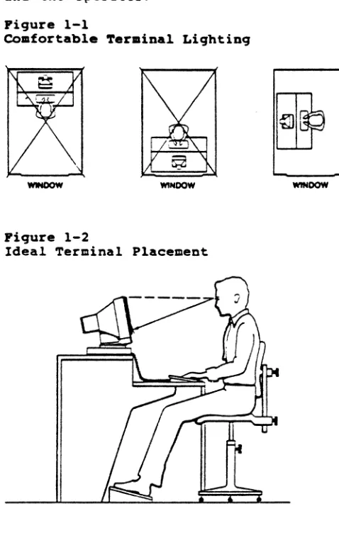
Selecting a Site
Choose a site with indirect lighting, away from windows and other sources of bright lights and glare, to avoid eyestrain. Figure 1-1 shows comtortable terminal lighting.
MaKe sure the terminal has adequate ventilation. Allow at
least 4 inches (10.2 cm) for ventilation on all sides.
Select furniture conducive to good working posture and place
the terminal at the correct height. The keyboard should be
lower than the screen.
Installation
HO~E: You need not worry about X-ray emissions. Tests
performed on TeleVideo terminals by Underwriters Laboratories indicate they emit virtually no radiation and pose no health hazard.
Figure 1-2 shows the ideal relationship between the terminal and the operator.
Figure 1-1
Comfortable ~.rminal Lighting
WINDOW
Fiqure 1-2
Ideal Terminal Placement
Installation
INSTALLATION STEPS
Now you are ready to plug in the l(eyboard and connect your
terminal to a computer and printer. Figures 1-3 and 1-4 show
front ftnd rear vie~s of the 9220 with ports, switches and
connectors marked.
Pigure 1-3
9220 Terminal, Pront View
CONTR ... ST ADJUSTOR
Pigure 1-4
_ _ - - " " ' ' ' " SWITCH
KEYBO ... D
9220 Terminal, Back View
POWERCABI.E~~
OOC<U~
III ... CURRENT
LOOP PORT
""'NT'ER ""COIIPOSI~~ITEn'
PORT VIDEO 0II1'LEr
Installation
COnnectinq the ~eyboard
Insert the preprinted leqend label into the bezel directly
above the row of function keys. Save the other blank label.
Pluq the ends of the coi led keyboard cable into the back of the keyboard case and the front of the terminal (Fiqure 1-3).
Before You Connect the ~er.inal
Make sure the terminal voltaqe settinq matches your electrical
outlet. The terminal should carry a label st~tinq whether its
settinq is 115 volts or 230 volts ac power. Call the
~eleVideo Customer Service Department for instructions if you want to chanqe the voltaqe settinq.
If you need a neutral fuse to meet international standards. ask your dealer or service technician to install it for you.
Measure the distance between the terminal and your computer or
modem. If it is less than SO feet, you can connect the two
with an RS-232C interface cable (with a 25-pin connector).
If yo~r CCL:puter is mo!'e than SO feet away, use a 20 mA current loop interface with an eiqht-pin connector.
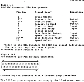
COnnectinq the ~er.inal With an RS-232C Interface
If you use an RS-232C interface, follow these steps:
1. Compare the suqqested connector pin assiqnments, listed
in Table 1-1, with you!' computer's. (Figure 1-5 shows
the terminal pin numbers.) If necessary, ask your
service technician to chanqe the interface cable pin af:siqnments.
BO~E: Not all computer connector pins are compatible
with standard RS-232C pin assiqnments. See Table 1-1 for
required siqnals. If your terminal does not operate
properly, check your computer manual or company service department for assistance in wirinq the interface cable.
2. Connect the ·interface cable to the terminal port labeled
RS-232 COMPUTER and the computer RS-232C port.
Installation
Table 1-1
RS-232C Connector Pin Assi9nments
Pin No. Si9nal Name- Direction
1 Frame Ground
2-- Transmit Data Output
3·· Receive Data Input
4 Request to Send Output
5 Clear to Send Input
6 Da ta Set Ready Input
,
..
Signal Ground8 Data Carrier Detect Input
12 Speed Indicator Input
20··· Data Terminal Ready Output
23 Speed Select Output
·Refer to the EIA Standard RS-232C for si9nal definitions. ··The terminal requires these signals.
···Modems often require pin 20.
Fiqure 1-5
Pin Numbers (25-Pin RS-232C Connector)
13
@~@@@@@@@@@(~@'
@@@@@@-!)@@@@@
,.
... c- .•
Connecting the Terminal With a Current Loop Interface
The 9220 or your computer can supply the 20 mA power source to
drive a current loop signal. Table 1-2 shows the-9220 current
loop connector pin assignments, and Appendix H shows terminal-host interface wiring for various power source configurations.
To connect the terminal with a current loop interface:
1. ~SK your service technician to correctly wire the
interface between the terminal and host. (Figure 1-6
shows the eight-pin 20 mA connector numbers.)
2. Connect the interface cable to the eight-pin current loop
connector (see Figure 1-4) and the host current loop connector.
Table 1-2
20 mA Current Loop Connector Pin Assiqnments
Pin No.*
1
2 3 5
7
8
*Jumper pins 4 and 6.
Fiqure 1-6
Siqnal
-l2V 20 mA source
Transmit Data Receive Data Transmit Data
Receive Data Ground
Pin Numbers (a-Pin 20 mA Connector)
~
qjrz~
qy
~
qj
\Y
~L1qj> ~
, I
Connectinq the Terminal to a Printer
The 9220 has a standard 25-pin printer port.
Installation
Polarity
Neqative Negative Positive Positive
1. As you did with your computer, check your printer
connector against the terminal printer port pin assignments, shown in Table 1-3.
2. Connect an RS-232C interface cable with a 2S-pin
connector to the 25-pin port at the back of the terminal labeled PRINTER. See Figure 1-4 for the location of the printer port.
NOTE: Not all printer connectors are compatible with
standard RS-232C pin assignments. See Table 1-3 for
required signals. If your printer does not operate
properly, check the manual or company service department for assistance in wiring the interface cable.
Installation
Table 1-3
25-Pin RS-232C Printer (DCE) Interface Connector Assignments
Pin No. Signal Name* Direction
1 Frame Ground
2 Receive Data Input
3 Transmit Dat'" Output
4 Request to Send Input
5 Clear to Send Out out
6 Data Set Ready Output
7 Signal Ground
8 Data Carrier Detect Output
11·- Printer Busy
20 Data Terminal Ready Input
*Reference EIA Standard RS-232C for signal definitions.
·*Nonstandard handshaking signal used by several printers such
as Epson, Texas Instruments, and Okidata. Pin 11 is not a
control line for the 9220 and must be connected to pin 20. If you want to use pin 11 instead of pin 20, call a
qualified service technician.
Plugging In and Turning On the Terminal
Now you are ready to plug in the terminal and turn it on.
1 . P 1 u g the po w e rca b 1 e i n t o t he t e r min a 1 and in t 0 a
grounded warl outlet. Figure 1-4 shows the power cable
outlet at the rear of the terminal.
In the United States, use a 3-prong electrical outlet with a National Electrical Manufacturers Association
(NEMA) Standard 5-15R rating. If you use a two-prong
adapter, ground it with a pigtail.
2. Push the white dot on the ON/OFF switch on the front of
the termina 1 (Figure 1-3).
3. Listen for the terminal bell, after about a second, and
loor; for the cursor in the top left corner of the screen
after 10 to 15 seconds. If the screen remains dark, go
to ';he next step.
4. Adjust the screen contrast with the roller on the left
side of the grooved panel below the screen (Figure 1-3).
5. Adjust the angle of the terminal by pushing on the case
until you can see the screen easily.
Installation
IBSTALLATIOH SUMMARY
1. Unpack and inspect the terminal.
2. Pluq the keyboard cable into the terminal and the
keyboard.
3. Check the terminal voltaqe settinq.
4. Connect the appropriate interface cable between the
computer system and the terminal.
5. Attach a printer interface cable (if you are connectinq a
printer to the terminal).
6. Pluq the power cord into both the terminal and the wall
outlet.
7. Turn on the terminal, listen for the beep, watch for the
cursor to appear, and adjust the screen contrast and tilt.
Before you t~y to use the terminal, read the next chapters on
terminal set up and operation.
2. SETTING OPERATIBG VALUES
When you turn on the terminal, i t is ready to operate. Its
factory default operating values are set when it is
manufactured. This chapter tells you how to reset the default
values from the keyboard.
NOTE: You can temporarily change some set up values with
programming commands in Chapter 5. The set up fields then
display the current (changed) values.
BOW SET UP WORKS
To change the terminal operating values, select new values
fro~ a series of set up screens. Each screen contains fields that let you:
* *
•
Choose a value
Ta!<:~ an action Enter text
Set Up Procedure
1. Press the Set Up key (F3). The screen changes to display
the Set-Up Directory. Don't worry about your previous
screen display: when you leave set up it returns.
NOTE: You can enter set up any time, but if the computer
is sending data, the screen stops receiving incoming data until you leave s'et up.
2. Move the cursor from one field to another with the Up,
Down, Right, and Left keys.
3. Press Enter to take an action, change values, or display
an empty text field. See the tables in this chapter for
the operating values in each field.
BOTE: You can display set up screens but cannot change
values when set up is disabled by a programming command.
Setting Operating Values
4. When you finish in each field, you can
•
•
•
Move to another field (with the cursor keys), or
Move to the next set up screen (by moving the cursor to the To Next Set-Up field and pressing Enter), or
Return to the Set-Up Directory (by moving the cursor to the To Directory field and pressing Enter).
5. To save new operating values in nonvolatile (permanent)
memory:
•
•
Enter CTRL S from any set up screen, or
Return to the Set-Up Directory. Move the cursor to
the Save field and press Enter.
HOTE: Leaving set up does not automatically save the new
set up values in nonvolatile memory. You must save the
values in the separate step described above.
You can save set up values changed with a programming command by entering set up and using one of the above methods.
6. To leave set up and return to normal operation:
•
•
Press Set Up (F3) from any set up screen, or
Return to the Set-Up Directory. Move the cursor to
the Exit field and press Enter.
Setting Operating Values
Set Up Categories
Table 2-1 lists the parameters in each set up category.
Table 2-1
Set Up Categories
liame
Set-Up Directory
Display
General
Communi-cations
Printer
Keyboard
Tabs
9220
Controls
Access to other screens, saving and
resetting operating values, communication mode.
Columns per line, autowrap, scrolling, display controls, screen and cursor appearance.
Programming and bit-control modes: user-definable keys and functions: keypad, cursor keys, and new line aedes.
Baud rate (transmit and receive), handsha~ing,
data word, parity, echo, port, disconnect, character transmission.
Baud rate, print mode, data word, parity, print region, character transmission, terminator character.
Keycap character selection, shift lock, auto repeat, keyclick, bell, Break key, answerback message.
Setting and clearing tab stops.
Additional operating parameters not available
in the VT220: intensity, hertz rate, Back
Space key, screen saver, status line, transmit control, key control, print mode, terminal 10, compose character key.
Setting Operating Values
THE SET UP SCREENS
Figures 2-1 through 2-8 show the set up screens, with the default values iri each field (where applicable).
Tables 2-2 through 2-9 describe the choices in each field. Values that must match the operating values of your computer or printer are shown in bold print.
Pigure 2-1
Set-Up Directory
Table 2-2
Set-Up Directory Pields
Action/Text/
Pield Values
Display Action
General Action
Comm Action
Printer Action
Keyboard Action
Tab Action
'I'VS9220 Action
Description
The Display screen appears.
The General screen appears.
The Communications screen appears.
The Printer screen appears.
The Keyboard screen appears.
The Tab screen appears.
The TVS9220 screen appears.
Table 2-2 Continued Set-Up Directory Fields
Field
Conv/Block/ Local
Action/Text/ Values
Conversa-tional
Blocle
Lec<-l
Clear Display Action
Clear Comm Action
Reset Action
Terminal
Recall Action
Save
Set-Up=
Auswahlbild=
Modes de
fonct.
=
Action
Engl ish
Deutsch
Francais
Setting Operating Values
Description
Permits simultaneous
transmission and reception of data. -Keyboard entries go only to the computer, unless you select local echo in the Communications screen.
Sends keyboard entries to the screen only: permits block transmission to the computer. Terminal may receive data from the computer.
Sends keyboard entries to the
screen only. No communication
wi th the computer.
Removes all data from the screen when you leave set up mode.
Stops all communication (including printing) between host and terminal and clears all terminal buffers.
Partial reset: see Table 5-4. Does not clear the screen.
Power-off reset. Disconnects
terminal and host: clears the screen: restores the last values saved in nonvolatile memory.
Saves set up values in nonvolatile memory.
Set up screens appear in English.
Set up screens appear in German.
Set up screens appear in French.
Table 2-2 Continued Set-Up Directory Pields
Pield
Keyboard Language
Default
Exit
Action/Tezt/ Values
North American British (220) Flemish Canadian
(French) Danish Finnish German Dutch Italian
Swiss (French) Swiss (German) Swedish
NcrwE'!Gian French/Belgian Spanish
british (100)
Action
Action
Setting Operating Values
Description
Screen characters appear in the selected language character set. You can order matching British, French, German, Spanish and Italian keycap sets.
Default reset: restores the original factory default values.
NOTE: Defaul t reset va 1 ues
(like all other set up values) are only stored in temporary
memory. Unless you save them
before leaving set up. a power-off reset (Recall) will return
the values saved in nonvolati 1e memory.
Returns from set up mode to normal operation.
Pigure 2-2
Di.play Set-Up Screen
'fable 2-3
Display Set-Up Fields
Pield
Action/Text/ Values
To Next Set-Up Action
To Directory Action
Columns 80
132
Controls Interpret
Display
Auto Wrap No Auto Wrap
Auto Wrap
Scroll Smooth
Jump
Setting Operating Values
De.cription
Displays the General screen.
Returns to the Set-Up Directory.
Screen lines contain 80 columns.
Screen lines contain 132 columns.
The termiAal interprets (acts on) control codes.
The terminal displays and does not act on control codes.
Cursor does not wrap to the next line during data entry.
Cursor wraps to the start of the next line during data entry.
Scroll rate is 6 lines per second.
Data appears on the screen at the rate the computer sends it.
~able 2-3 Continued Display Set-Up Fields
Field
Background
Cursor
Dot Stretch
Action/rrest/ Values
Normal
Reverse
Cursor No Cursor
Blinking/ Steady
Block/ Underline
Dot Stretch
No Dot Stretch
Setting Operating Values
Description
Screen is dark with light text.
Screen is-light with dark text.
Selects visible or invisible cursor.
Selects blinking or steady cursor.
Selects block or underline cursor.
Each character formation dot (pixel) is horizontally
stretched to cover the dot to
its right. Characters appear
thick.
Characters are formed normally.
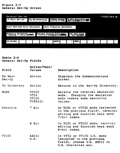
Figure 2-3
General Set-Up Screen
'l'able 2-4
General Set-Up Fields
Field
To Next Set-Up
To Directory
Mode
Controls
VT100
Action/'l'ext/ Values
Action
Action
VT220 VT52 VT100 TVS9220
7 Bit
8 Bit
ASCII U.K.
Setting Operating Values
Description
Displays the Communications screen.
Returns to the Set-Up Directory.
Selects the terminal emulation
mode. Changing the emulation
mode resets some operating values.
In 9220 or VT220 mode (selected in the previous field), terminal editing and function keys send 7-oi t codes.
In 9220 or VT220 mode, terminal editing and function keys send a-bit codes.
In VT52 or VT100 U.K. mode (selected in the previous field), choose U.S. ASCII or U.K. character set.
~able
2-4 Continued
General Set-Up Pield.
• Pield
U.er Defined
Key.
ActiOD/~ez.tl
Value.
Unlocked
Locked
U.er Peatures Unlocked
Locked
Keypad
Numeric
Application
Cursor Keys
Normal
Application
New Line
No
New Line
Settinq Operatinq Value.
Description
Lets application proqram
reproqram the function key ••
Prevents the host from
reproqrallllinq the function key ••
Lets the host application
pr09ram chanqe auto repeat,
smooth/jump scroll,
normal/reverse video, keyboard
lock/unloCk, and tab parameters.
BOTE:
Certain application
proqrams expect to control these
parameters.
If your host is
runninq one of these prQ9rams,
select the unlocked
value.
The host cannot chanqe
operatinq parameters.
Numeric keypad keys send ASCII
display and control characters.
Numeric keypad keys send codes
in Table
5-6.Cursor keys send cursor movement
commands.
Cursor keys send codes in Table
5-5.New line mode disabled.
Return key sends carriaqe return
and line fe.d commands: terminal
responds to line feed command
with carriaqe return and line
feed cursor movement.
Pigure 2-4
Coaaunications Set-Up Screen
'rable 2-5
eoaaunications Set-Up Fields
Action/Text! Values
To Next Set-Up Action
To Directory
Transmit-Receive=
Action
7S
110
lS0 300
600
1200 2400 4800 9600 19200
Transmit 7S
110
150 300 600 1200 2400 4800 9600 19200
Setting Operating Values
Description
Displays the Printer screen.
Returns to the Set-Up Directory.
Selects the main (computer) port transmission baud rate.
Selects the main (computer) port reception baud rate. 'rrans.i t sets the reception rate to match the transmission (selected in the previous field).
NOTE: T=ansmit and receive
rates need not match.
-Fields in bold print must match computer values.
~able 2-5 CODtiDued
COmmunications Set-Up Fields
Bandehakin9 Protocol
Bits
Parity
Parity Check
Stop Bit(s)
Action/~e'Stl
Values
XOFF at 64
XOFF at 128
None
DTR
8
7
No Even Odd Space Hark
Check
No Check
1
2
Settinq Operatinq Values
Description
Terminal send. X-Off to computer when receive buffer can hold only 64 more character ••
Terminal sends X-Off to computer when receive buffer can hold only 128 more characters.
No handshakinq protocol set between terminal and computer.
Enables DTR handshakinq protocol between terminal and computer.
Computer port transmits/accepts only a-bit data words to/from computer.
Computer port transmits/accepts only 7-bit data words to/from computer.
Selects main port parity settinq.
Terminal checks the parity of data received from the host.
Terminal does not check parity.
Data words contain one stop bit.
Data words contain two stop bits.
-Fields in bold print must match the computer's values.
Setting Operating Values
Table 2-5 Continued
Communications Set-Up Fields
Field
Local Echo
Port
Disconnect,
Transmit
Action/Text/
Values Description
No Local Echo Keyboard data goes to the host
only (not to the screen) in conversational mode.
Local Echo
EIA Port, Data Leads Only
EIA Port, Modem Control
20 mA Port
2 s Delay
60 ms Delay
Limited
Unlimited
Keyboard data goes to both the screen and the host in
conversational mode.
Select this value when you connect the terminal to a computer with an RS-232C interface.
Select this value when you
connect the terminal to a modem.
Select this value if you connect the terminal to a computer with a current loop interface.
Disconnect between terminal and host occurs when Data Carrier Detect is lost for 2 seconds.
Disconnect between terminal and host occurs when Data Carrier Detect is lost for 60 ms.
Character transmission speed is never greater than 150-180 characters per second,
no matter what the baud rate is.
Removes the character transmission speed limit.
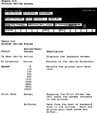
Figure 2-5
Printer Set-Up Screen
Table 2-6
Printer Set-Up Fields
Act ion/'1'ext/ Values
'1'0 Next Set-Up Action
'1'0 Directory
Speed=
Print Mode
Action
75 110
150 300 600 1200 2400 4800 9600 19200
Normal
Buffered
Setting Operating Values
Description
Displays the Keyboard screen.
Returns to the Set-Up Directory.
Selects the printer port baud rate.
Pressing the Print Screen Key (F2) sends the screen contents to the printer.
Data from the host or Keyboard
goes to the printer. Main and
printer port baud rates may di £fer.
-Fields in bold print must match the printer's values.
Setting Operating Values
~able 2-6 Continued
Printer Set-Up Fields
Print Hode (continued)
Bits
Parity
Stop Bit(s)
Print Region
Action/Text/ Values
Auto Print
Description
Terminal sends the current line of text to the printer whenever
it receives a vertical tab (hex
~B), line feed (hex ~A), or form
feed (hex ~C) command.
Print Screen key functions in this mode.
Bidireetional Enables two-way communication
between deviees attached to the terminal's computer and printer
ports. Both devices must have
the same baud rate, parity, word structure (bit mode), and stop bits.
B
7
No Even
Odd
Space Hark
1
2
Full Page
Terminal sends all
B
bits ofdata words to the printer.
Terminal sends only 7-bit data words to the printer.
Selects printer port parity setting.
Data ~ords sent to the printer
contain one stop bit.
Data words sent to the printer eontain two stop bits.
Page print eommand prints entire screen.
Scroll Region Page print eommand prints
scrolling region.
*Fields in bold print must match the printer'. values.
Table 2-6 Continued Printer Set-Up Fields
Pield
Printed Characters
Action/Tezt/ Values
ASCII /U.K. Only
ASCII/U.K. And Line Dr awin9
All
Characters
Settin9 Operatin9 Values
Description
Terminal sends to printer only ASCII and U.K. characters.
Terminal sends to printer ASCII. U.K. and special line-drawi n9 characters.
Terminal sends all characters to printer.
Terminator No Terminator Terminal does not send a
terminator character to the computer after a page print.
=
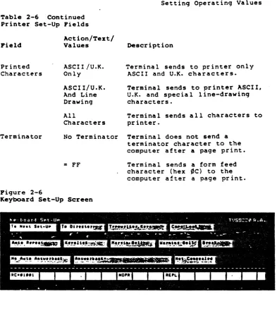
FFPigure 2-6
Keyboard Set-Up Screen
Terminal sends a form feed
character (hex ~C) to the
computer atter a page print.
Setting Operating Values
'rable 2-7
~eyboard Set-Up Fields
Field Action/"fest/ Values Description
To Next Set-Up Action Displays the Tab acreen.
To Directory
Keys
LOCK
Auto Repeat
Keyclick
Action
Typewriter
Data
Processing
Returns to the Set-Up Directory.
Charactera on the left aide of the key cap appear on the screen.
Characters on the right side of the key cap appear on the screen •.
BOTE: North A~erican keyboards do not have
characters on the left and right sides of the to.sycaps.
Caps
Shift
Auto Repeat
Only the alpha keys produce capital letters when you press the Lock key.
All character keys produce uppercase characters when you press Lock.
Character keys and most special keys repeat when held down.
No Auto Repeat No keys repeat.
BOTE: If you select No Key Control in the
TVS9220 screen, you cannot change the auto repeat value.
Keyclick Keys click when pressed.
No Keyclick Keys are silent when pressed.
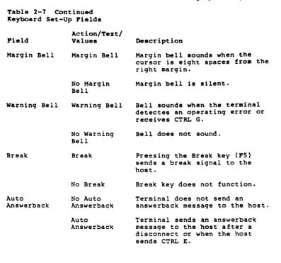
Table 2-7 Continued Keyboard Set-Up Pields
Pield
Marqin Bell
Warninq Bell
Break
Auto
AnswerbacK
Action/Text/ Values
Marqin Bell
No Marqin Bell
Warninq Bell
No Warninq Bell
BreaK
No Break
No Auto Answerback
Auto
Answerback
Settinq Operatinq Values
Description
Marqin bell sounds when the cursor is eiqht spaces from the riqht marqin.
Marqin bell is silent.
Bell sounds when the terminal detectes an operatinq error or receives CTRL G.
Bell does not sound.
Preesinq the Break key (PS) sends a break 8iqnal to the host.
Break key does not function.
Terminal does not send an
answerback messaqe to the host.
Terminal sends an answerback messaqe to the host after a disconnect or when the host sends CTRL E.
~able 2-7 Continued
~eyboard Set-Up Fields
Field
AnswerbaCK-Action/~ezt/
Values
<lIessage>
Setting Operating Values
Description
Press Enter, then type up to 30 characters in the status line as the answerbacK
lIessaqe. If you lIake a lIistake,
press Enter twice to start over again.
~IBGI Displaying the answerback entry field in the status line automatically erases the current message when you
press Enter again. If you do
not want to change your present answerback lIessage, you lIust retype it.
When you press Enter again, your new message appears in the
AnswerbacK- field in place of the old one.
Concealed Message
Not Concealed AnswerbacK message appears in
the answerback field.
Concealed <Concealed> appears in the
answerback field in place of the answerback message.
WARBIBGI You cannot redisplay a
concealed message. You must
move the cursor bacK to the Answerback field and press
Enter. This clears your
previous answerback message and cancels the Concealed value.
Figure 2-7
Tab Set-Up Screen
Table 2-8
Tab Set-Up Fields
Field
To Next Set-Up
To Directory
CI ear All Tabs
Set 8 Column Tabs
Tab ruler
(uppercase T's)
Setting Operating Values
Description
Displays the TVS9220 screen.
Returns to the Set-Up Directory.
Clears all tab settings.
Sets tab stops every eight columns.
Cursor changes to block. Move i t with a
cur sor 'Key, Tab, or Back Tab key to the desired column: then press Enter to set or delete a tab stop.
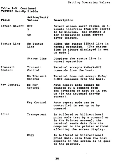
Pigure 2-8 TVS9220 Screen
'l'able 2-9
TVS9220 Set~Up Pields
Pield
Act ion/'l'ex t/ Values
To Next Set-Up ~ction
To Directory
Normal Intensity=
Hertz
Back Space/
D~lete
~ction
Half
Full
60 Hz
50 Hz
Back Space
Delete
Setting Operatinq Values
Description
Displays the Display screen.
Returns to the Set-Up Directory.
Characters are half intensity.
Characters are full intensity
Screen refreshes at 60 Hz ( dome s tic) .
Screen refreshes at 50 Hz (international).
Back Space key sends back space command.
BacK Space Key sends delete code (hex 7F).
Table
2-9Continued
TVS9220
Set-Up Pields
Action/Test/
Pield
Values
Screen Saver-
Off
5
-60
Status Line
No Status
Line
Transmit
Control
Key Control
Status Line
Transmit
Control
No Transmit
Control
No Key
Control
Key Control
Transparent
Copy
Setting Operating Values
Description
Select screen saver values in
5-minute intervals from Off (zero)
to
60minutes.
See Chapter 3
for information about screen
saver feature.
Hides the status (25th) line in
noraal operation.
(The status
line is always displayed in set
up mode.)
Displays the status line in
normal operation.
Terminal accepts X-On/X-Off
commands from the host.
Terminal does not accept X-onl
X-Off commands from the host.
Auto repeat mode cannot be
changed by a command from
the
keybo~rdor host or in set
up (in the Keyboard Set-Up
screen) •
Auto repeat mode can
becontrolled in set up or by
command.
In buffered or bidirectional
print mode (set by a command or
in the Printer screen), the
terminal sends data from the
computer to the printer without
affecting the screen display.
In buffered or bidirectional
print mode, data from the host
appears on the screen .s it 90es
to the printer.
Table 2-9 Continued TVS9220 Set-Up Fields
Field
Action/Text/ Values
Terminal 1.0.- 98762:1:2: 6:7:8c.
Terminal 1.0.- Text
Compose On
Off
Settinq Ooeratinq Values
Description
Default terminal 1.0.
Proqrammable terminal 1.0. To
chanqe the terminal 1.0., follow the instructions in Table 2-7 for proqramminq the terminal'. answerback .essaqe.
Character compose key enabled.
Character compose key disabled.
3. OPERATIHG THE 9220
This chapter lis~s the ~eys and explains how to operate the
terminal from the keyboard. It also describes the features of
the terminal screen.
The keyboard contains char~cter keys, editinq keys, special
keys and function keys. They are qrouped in four areas:
main ~eypad, cursor-edit keypad, numeric keypad, and function
key row.
Character keys and many editinq and special keys repeat when
pressed for more than one-half second. Function keys do not
repeat.
Fiqure 3-1 9220 Keyboard
MAIN KEYPAD
FUNC'TlON KEY ROW
33
CURSOR-EDIT KEYPAD
NUMERIC
Operating the 9220
Character Keys
The unshaded Keys in Fiqure 3-2 are the character keys. They
include the alphabet, numbers
(~through 9), punctuation
marKS, symbols, and the space bar •
•
O~Z:When you press a character key, its code may go to the
computer, but not to the screen, depending on your
communication mode and local echo settinq. See the section
later in this chapter about communication aedes.
Figure 3-2 shows the North American keyboard.
The 9220 offers
various options for displaying alphanuaeric characters from other
languages. You can select one of 15 other character seta in set
up (see Table 2-2): Appendix E shows the corresponding keyboard
layout of each character set. You can form individual characters
with the character compose sequences explained later in this
chapter (Table 3-4). Or you can enable the multinational
supplemental character set with a proqramming command in Chapter
S.
See the section called CHARACTER SETS in Chapter 5.
Pigure 3-2
Character Keys
Operation
Editing Keys
Editing Keys do not display characters: they send editing
commands. Appendix G lists the editing key codes. Keys
repeat unless noted in Table 3-1 •
• O~E: The programming, communication and operating .odes
affect editing keys. If a key does not operate as described
in Table 3-1, its function may be changed by a terminal .ode.
Fiqure 3-3 Editinq Keys
'I:.IC. • • • 1
-EJmE]EJ
'1'able 3-1
Editing Keys
Key liame
BaCK Space
BaCK Tab
CE (clear entry)
I • - f
-EEl ..
'ru
t
I-I"~
. II-RIO , .. , ..
EI
-
...
... ... ...
7. 8 9
..
4. 5 & a 2 3-..
•
Effect
Moves the cursor left one character or
sends a DEL character (hex 7F), depending
on value selected in set up.
Moves the c~rsor left to the previous tab
stop. Operates in 9220 mod::- only.
Erases the field between the previous and
next tab stops. Returns the cursor to the
previous tab stop. Operates in 9220
emulation mode only. Does not repeat.
Operation
Table 3-1 Continued
Editing Keys
Key Haae
Left
Up
Right
Down
Enter
Line Feed
~rint Screen (F2)
Ctrl-Print Screen
Return
Send
Tab
Shift-Tab
Effect
Moves the cursor left one character. Cursor stops at the line's left margin. Moves the cursor up one line in the same
column. Cursor stops at the upper
boundary of scrolling region or top of the screen.
Moves the cursor riqht one character. Cursor stops at the end of the line.
Moves the cursor down one 1 i ne in the same
column. Cursor stops on the bottom line
of the scrolling area or screen.
In numeric keypad mode, same ~s Return key.
In application keypad mode. sends ESC 0 M.
Moves the cursor down one 1 ine in the same
column. When the cursor reaches the
bottom of the scrolling region. data scrolls up one line.
Sends contents of the screen to the printer in normal or auto print modes.
Toggles auto line print mode on and off.
Sends carriage return or carriage return and line feed commands, depending on your
choice in set up. Does not repeat.
During block mode. sends all data between
home and the cursor to the computer. Does
not repeat.
Moves the cursor forward to the next
typewriter-style tab stop. Duplicated on
main and numeric keypads.
Sets a typewriter-style tab stop at the cursor.
Operation
Special Keya
Figure 3-4 shows the special keys, and Table 3-2 explains their effects.
Pigure 3-4 Special Keys
' , " .
II:. 1;:' t . _ •
.
-,
EJEJEJEJEJ
" " .
~.
EJEJ" I ..
' .. '
.
:c,·,··
t 4 • t - 1
-I.. I
EJEl .. I
... 1
1-' .. ·
11-EEEJE]
I::
I~I; I:
I:
I: U: I:
I;
I~- I~t:"1: t
I=:. I
-
-
-
-I
-
...
...
..,
,...
t-
IQ
~w ~EIRP P IU
II
1
0I
PI: I:
I
-
-
::..
=-1
7•
i.
P-....
~-
IA
liS ~oIF
~GIIH
~JII<
IL
I-
r
1-o.
t 4 5 6
,
-,
..
,'-
IZ IX
ftc II
V1
8IN
~Mt
r n:
11-
1=1
..
•
.. I •
1 2 3~=
I
Table 3-2 Special Keya
Key Naae
Break (F5)
Shi ft-Break
Ctrl-Break
-j . ~'. -: .. -.
-
•
•
Effect
Senes a break signal (unless disabled in
set up). Holds the communication line
(pin 2 of the main RS-232C connector) in the _ state (low) for 250 milliseconds. How your computer responds to the signal
depends entirely on its proqram. A break
signal may disconnect a modem. Does not
repeat.
Disconnects terminal from DTR (data terminal ready) ana RTS (request to send) lines for 250 milliseconds.
Sends the terminal answerback message to the host.
Operation
Table 3-2 COntinued
Special Keys
Key Baae
Compose Character
Ctrl (control)
Delete
Esc (escape)
F4
Find
Hold Screen (Fl)
Insert Here
Loc Esc
(Shift-Esc)
Effect
Lets you create supplemental characters not
directly available from the keyboard.
See
the section on composin9 characters in this
chapter. Operates only in 9220 and VT220
mode..
Hay
bedisabled in set up.
Pressed with some character keys to send
operatin9 commands (control characters).
Pressed with some editin9 and special keys
to cause terminal operations.
Displays no character. Operation
determined solely by application prQ9ram.
When pressed immediately before pressin9 a
character key, causes the character key to
s-nd an operating command (escape
sequence).
Does not repeat.
No function.
Has no default function and displays no
character.
Operation determined solely by
application prQ9ram.
Operates only in
9220 and VT220 emulation modes.
Halts data flowin9 to the screen from the
computer until pressed a9ain.
Does not
repeat.
Has no default function and displays no
character.
Operation determined solely by
application proqram.
Operates only in
9220 and VT220 emulation modes.
Press instead of Esc to .end escape
sequence commands from the keyboard to the
terminal only.
Does not repeat.
Operation
Table 3-2 Continued
Special Keys
Key Hame
Lock
Next Screen
PF1-PF4
PreY Screen
Reoove
Reset
Ctrl-Reset
Select
Set Up (F3)
Shift
Effect
Capitalizes all alphabetic keys. May
select upper character on symbol keys. depending on the parameter you choose in
set up. Does not repeat.
Has no default function and displays no
character. Operation determined solely by
application program. Operates only in
9220 and VT220 emulation modes.
No default function. Keys display
characters from the supplemental character set in 9220 or VT220 modes and uppercase
P. Q. R. and S in VT100 mode.
Has no default function and displays no
character. Operation determined solely by
application program. Operates only in
92~O and VT220 emulation modes.
Has no default function and displays no
character. Operation determined solely by
application program. Operates only in
9220 and VT220 emulation modes.
No function when pressed alone.
Resets the terminal to power-off (nonvolatile memory) values.
Has no default function and displays no
character. Operation determined solely by
application program. Operates only in
9220 and VT220 emulation modes.
Displays the Set-Up Directory. Press
again to leave set up. Does not repeat.
Capitalizes letters and selects the upper characters of other keys.
Operation
Function ~eys
Function keys F6 through F20 (also called user-defined keys)
send codes to the computer that programmers use. (Fl through
F5 are editing or special keys.) In 9220 and VT220 emulation
modes you can reprogram (load a message into) keys F6 through
F20. with a proqramming command. See Chapter 5 for the default
codes of those keys and the command to reprogram them.
Two keyboard legend labels come with the terminal. One shows
the operations of keys Fl-P5, plus the cursor movement
functions of P11-P14 in VT100 and'VT52 modes. If you reproqram function keys F6-P20, you can write the new values on the other, unprinted label and insert it above the keys.
Table 3-3 describes how the keys operate in each terminal emulation mode.
Figure 3-5
Function ~ey.
'l'able 3-3 Function Keys
Itey lialDe
F6-F10 Do, Help, F17-F20
Shifted F6-F10 Do, Help, F17-F20
Fll
(unshifted and shifted)
FJ2
(unshi £ted and shifted)
F13
(unshifted and shifted)
Fl4
(unshifted and shi fted)
Emulation 9220 VT220 VT100 V'l'S 2 9220 VT220 VT100 VTS2 9220 VT220 VT100 V'l'S2 9220 V'l'220 VT100 V'l'S2 9220 VT220 VT100 VTS2 9220 VT220 VT100 VTS2 Effect Reprogrammable Nonprogrammab1e No function No function
ReprograllUllab1e Reprogrammab1e No function No function
Same as F6-F10 Same as F6-F10
Up key
U~ key
Same as F6-F10 Same as F6-F10 Down key
Down key
Same as F6-F10 Same as F6-F10 Left key
Lef.t key
Same as F6-F10 Same as F6-F10 Right key Right key
41
Operi'!tion
CONTROLLIHG THE 'TERMINAL FROM 'l"BE ItEYBOARD
The editing and special keys control many terminal operations. But before you enter data or operate the terminal, you should understand the effects of the coaaunication modes, explained below.
NO'TE: Sendinq the programming commands in Chapter 5 from the
keyboard lets you control even more terminal functions. The
section in Chapter 5 called Entering Commands From the Keyboard explains how to send programming commands from the keyboard.
Communication Modes
The 9220 has three communication modes:
Block Local
Conversational
Key codes go immediately to the computer in conversational mode, and the terminal can transmit and receive data
simultaneously. Unless your computer sends back (echoes) the
key codes, data does not appear on the screen when you prp.ss character keys, and editinq keys do not affect screen data.
If you select local echo mode in set up, key codes go to both
the computer and the screen. Characters you type appear on
the screen, and editing keys affect screen data.
In block communication mode, characters typed at the keyboard go only to the screen, and editinq keys affect screen data. Pressing Send transmits screen data to the computer (as
explained later in this chapter). However, the terminal can
receive data from the computer any time.
In local communication mode, the terminal has no communication with the COMputer.
Operation
Editing and Sending Data
The editing Keys (described in Table 3-1) move the cursor, change data on the screen, and send data to the computer and printer.
NOTE: If the editing Keys do not function as described in
Table 3-1, checK the terminal's com~unication and local echo
modes, described in the previous sections.
Pressing the Print Screen Key (F2) during normal or auto print mode sends the current screen display to your printer.
In bloCK mode, the Send Key sends a l l data on the screen, from the home position through (and including) the cursor position, to the host.
Figure 3-6
Data Sent by the Send Key
I ,
HOME CURSOR
Resetting the Terminal
To reset the terminal, press Ctrl-Reset. This is the same as
turning the terminal off and bacK on again. All operating
values return to the last values saved in nonvolatile memory.
Operation
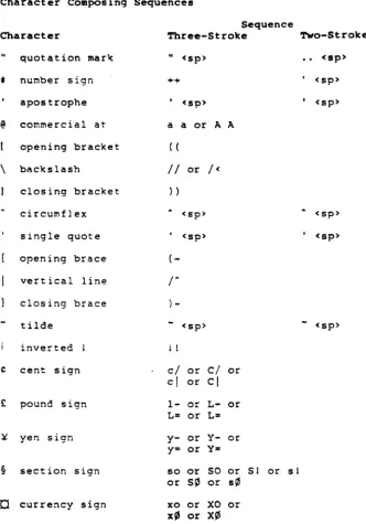
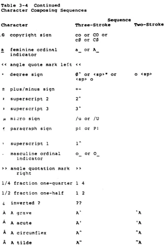
Composinq Characters
In 9220 and VT220 modes. you can create multinational
characters from the keyooard by pressinq certain alphanumeric
keys in sequence. Taole 3-4 lists the characters and
correspondinq two-stroke and three-strok@ sequences.
Start three-stroke compose sequences, availablp. on all 9220 keyboards, by pressinq the Compose Character key.
Two-stroke sequences, which are not available on the North
~merican keyooard. use a nonspacing diacritical mark followed
by a standard character. Nonspacing diacritical marks are the
grave accent, accute accent, circumflex accent, tilde mark,
diaeresis mark (umlaut), and ring mark. The two-stroke method
cannot create all characters.
Follow this procedure to compose characters:
1. Locate the character you want to create in the first
column of Taole 3-4.
2. Locate the corresponding alphanumeric characters for
either a two-stroke or three-stroke sequence in the second or third column of Taole 3-4.
If you have a North American keyboard or no characters appear in the two-stroke column of Taole 3-4. start a three-stroke sequence oy pressing the Compose Character key.
3. Type the two characters that correspond to the character
you want to create.
BOTE: Press the keys in the order shown 1n the taole.
COMP appears in the status line durinq a character compose sequence.
The sequence aoorts without creating a character if you
•
•
Press the Back Space key Ente~ an invalid sequenceOperation
Table 3-4
Character Composing Sequences
Sequence
Character Three-Stroke Tvo-Stroke
quotation marl( II
<sp>
·
.
<sp>t nUr.lber sign ++
·
<sp>apostrophe <sp>
,
<sp>@ cOr.lrnercial at a a or A A
opening bracket ( (
\ bacKs lash
II
or1<
closing bracket
»
circumflex <sp> <sp>
single quote <sp>
·
<sp>opening brace
(-vert ical line
r
closing brace )
-tilde
-
<sp>-
<sp>inverted 11
C cent sign
c/
orci
orcl
orcl
£
pound sign l- or L- orL= or L=
¥ yen sign y- or y- or
y= or y=
§ section sign so or SO or 51 or s 1
or S¢ or s¢
a
currency sign xo or XO orx~ or X¢
Table 3-4 Continued
Character Composing Sequences
Operation
Sequence
Character ~ree-Stroke TWo-Stroke
,C copyright si~n
a
«
feminine ordin~l
indicator
angle quote marlc le!t
deqree sign
=
plus/minus sign2 superscript 2
superscript 3
JI. mi.:ro sign
..
I paraqraph signsuperscript I
masculine ordinal indicator
» anqle quotation marlc
right
1/4 fraction one-quarter
1/2 fraction one-half
i. inverted ?
A
A gra.veA
A acuteA
A circumflexi..
A tildeco or CO or
c0
orC0
a or A
«
0
A or<sP)-<sP) 0
+-2A
3-/u or /U
pI or PI
1-0 or 0
»
1 4
1 2
11
A'
A'
A-46
or o <sP)
Operation
Table 3-4 Continued
Character Composing Sequences
Sequence
Character 'l'hree-Stroke '!'wo-Stroke
A
A umlaut A" or A A,.,
A ring A* or A AIf. AE ligature AE
C
C cedilla C,E
E qrave E' 'EE
E acute E' 'EE
E circumflex