Volume 2007, Article ID 57086,7pages doi:10.1155/2007/57086
Research Article
An Efficient Implementation of the Sign LMS Algorithm
Using Block Floating Point Format
Mrityunjoy Chakraborty,1Rafiahamed Shaik,1and Moon Ho Lee2
1Department of Electronics and Electrical Communication Engineering, Indian Institute of Technology, Kharagpur 721302, India 2Department of Information and Communication, Chonbuk National University, Chonju 561756, South Korea
Received 11 July 2005; Revised 31 August 2006; Accepted 24 November 2006
Recommended by Roger Woods
An efficient scheme is presented for implementing the sign LMS algorithm in block floating point format, which permits processing of data over a wide dynamic range at a processor complexity and cost as low as that of a fixed point processor. The proposed scheme adopts appropriate formats for representing the filter coefficients and the data. It also employs a scaled representation for the step-size that has a time-varying mantissa and also a time-varying exponent. Using these and an upper bound on the step-step-size mantissa, update relations for the filter weight mantissas and exponent are developed, taking care so that neither overflow occurs, nor are quantities which are already very small multiplied directly. Separate update relations are also worked out for the step size mantissa. The proposed scheme employs mostly fixed-point-based operations, and thus achieves considerable speedup over its floating-point-based counterpart.
Copyright © 2007 Hindawi Publishing Corporation. All rights reserved.
1. INTRODUCTION
Sufficient signal-to-quantization noise ratio over a large dy-namic range is a desirable feature of modern day digital signal processing systems. While the floating point (FP) data format is ideally suited to achieve this due to nor-malized data representation, the accompanying high pro-cessing cost restricts its usage in many applications. This is specially true for resource-constrained contexts like battery-operated low power devices, where custom implementations on FPGA/ASIC are the primary mode of realization. In such contexts, the block floating point (BFP) format provides a viable alternative to the FP scheme. In BFP, a common expo-nent is assigned to a group of variables. As a result, compu-tations involving these variables can be carried out in simple fixed point (FxP) like manner, while presence of the expo-nent provides an FP-like high dynamic range.
Over years, the BFP format has been used by several researchers for efficient realization of many signal process-ing systems and algorithms. These include various forms of fixed coefficient digital filters (see [1–6]), adaptive filters (see [7,8]), and unitary transforms (see [9–11]) on one hand and several audio data transmission standards like NICAM (stereophonic sound system for PAL TV standard), the audio part of MUSE (Japanese HDTV standard), and DSR (Ger-man digital satellite radio system) on the other. Of the
vari-ous systems studied, adaptive filters pose special challenges to their implementation using the BFP arithmetic. This is mainly because
(i) unlike a fixed coefficient filter, the filter coefficients in an adaptive filter cannot be represented in the simpler fixed point form, as the coefficients in effect evolve from the data by a time update relation;
(ii) the two principal operations in an adaptive filter— filtering and weight updating, are mutually coupled, thus re-quiring an appropriate arrangement for joint prevention of overflow.
proposed scheme, however, requires a scaled representation for the step size, which has a time-varying mantissa and also a time-varying exponent. Separate time update relation for the step size mantissa is worked out. It is also shown that in order to maintain overflow free condition, the step size mantissa, at all times, must remain bounded by an upper limit, which is ensured by setting its initial value appropri-ately. Again, the weight update relation of the sign LMS algo-rithm is different from the LMS algorithm and thus new steps are needed for the computation of the update term, taking care so that neither overflow occurs, nor are quantities which are already very small multiplied directly. As expected, the proposed scheme employs mostly FxP-based operations and thus achieves considerable speed up over its FP-based coun-terpart, which is verified both by detailed complexity analysis and from the synthesis report of an FPGA-based realization. The organization of the paper is as follows: inSection 2, we discuss the BFP arithmetic and present a new block for-matting algorithm for FP as well as FxP data. Section 3
presents the proposed BFP realization of the sign LMS al-gorithm. Complexity issues vis-`a-vis an FP-based realization are discussed inSection 4while finite precision based simu-lation results as well as the FPGA synthesis summary are pre-sented inSection 5. Variables with an overbar indicate man-tissa elements all throughout the paper. Also, boldfaced low-ercase letters are used to denote vectors.
2. THE BFP ARITHMETIC AND A
BLOCK-FORMATTING ALGORITHM
The BFP representation can be considered as a special case of the FP format, where every nonoverlapping block ofN
incoming data has a joint scaling factor corresponding to the data sample with the highest magnitude in the block. In other words, given a block [x0,. . .,xN−1], we represent it in
BFP as [x0,. . .,xN−1]= [x0,. . .,xN−1]2γ wherexl(=xl2−γ) represents the mantissaxl forl = 0, 1,. . .,N−1 and the block exponentγis defined asγ= log2Max+ 1 +Swhere Max = max(|x0|,. . .,|xN−1|), “·” is the so-called floor
function, meaning rounding down to the closest integer and the integerSis a scaling factor, used for preventing overflow during filtering operation.
In practice, if the data is given in an FP format, that is, ifxl =Ml2el,l =0, 1,. . .,N−1 with|Ml| <1, and the 2’s complement system is used, the above block formatting may be carried out byAlgorithm 1.
Algorithm 1(Block-formatting algorithm). First, count the number, say,nlof binary 0’s (ifxlis positive) or binary 1’s (if
xl is negative) between the binary point ofMl and the first binary 1 or binary 0 from left, respectively. Computeemax =
max{(el−nl)|l=0, 1,. . .,N−1}. Shift eachMlright or left by (emax+S−el) bits depending on whether (emax+S−el) is positive or negative, respectively. Take the block exponent as
emax+S.
Note. For cases wherexlis negative withMlhaving only binary 0’s after the first nl bits from the binary point, nl should be replaced bynl−1 in the above computation.
When the data is given in FxP format, the correspond-ing block formattcorrespond-ing turns out to be a special case of the above, for which xl ≡ Ml, el = 0, and emax is given by
min{nl|l=0, 1,. . .,N−1}. Note that due to the presence ofS, the range of each mantissa is given as 0≤ |xl| <2−S. The scaling factorScan be calculated from the inner product computation representing filtering operation [3]. An inner product is calculated in BFP arithmetic as
y(n)=wtx(n)
=w0x(n) +· · ·+wL−1x(n−L+ 1)
2γ =y(n)2γ,
(1)
where w is a length L, fixed point filter coefficient vector, and x(n) is the data vector at the nth index, represented in the aforesaid BFP format. For no overflow in y(n), we need|y(n)| < 1. Since|y(n)| ≤ L−1
k=0|wk||x(n−k)| and 0 ≤ |x(n−k)| < 2−S, 0 ≤ k ≤ L−1, this implies that it is sufficient to haveS≥ log2(Lk=−10|wk|)in order to have |y(n)|<1 satisfied, where “·” denotes the so-called ceiling function, meaning rounding up to the closest integer.
3. THE PROPOSED IMPLEMENTATION
Consider a lengthLsign LMS based adaptive filter [13] that takes an input sequencex(n) and updates the weights as
w(n+ 1)=w(n) +μx(n) sgne(n), (2)
wherew(n)=[w0(n) w1(n) · · · wL−1(n)]tis the tap weight
vector at thenth index,x(n)=[x(n) x(n−1)· · ·x(n−L+1)]t, ande(n) = d(n)−y(n) is the output error corresponding to thenth index. The sequenced(n) is the so-called desired response available during the initial training period and
y(n)=wt(n)x(n) is the filter output at thenth index, with
μdenoting the so-called step size parameter. The operator sgn{·} is the well known signum function which returns values +1 or −1 depending on whether the operand is nonnegative or negative, respectively.
The proposed scheme uses a scaled format to represent the filter coefficient vectorw(n) as
w(n)=w(n)2ψn, (3)
wherew(n) andψnare, respectively, the filter mantissa vec-tor and the filter block exponent which are updated sepa-rately over n. The chosen format thus normalizes all com-ponents ofw(n) by a common factor 2ψn at each indexn. In our treatment, the exponentψnis a nondecreasing func-tion of n with zero initial value and is chosen to ensure that |wk(n)| < 1/2, for allk ∈ ZL = {0, 1,. . .,L−1}. If the data vector x(n) is given in the aforesaid BFP format as x(n) = x(n)2γ, where γ = ex +S, ex = log
2M+ 1, M = max(|x(n−k)| | k ∈ ZL) andSis an appropriate scaling factor, then, the filter output y(n) can be expressed as y(n) = y(n)2γ+ψn with y(n) = wt(n)x(n) denoting the output mantissa. To prevent overflow in y(n), it is required that|y(n)|<1. However, in the proposed scheme, we restrict
Since |wk(n)| < 1/2,k ∈ ZL, fromSection 2, this implies that it is sufficient to haveS ≥Smin = log2L, in order to
maintain|y(n)| < 1/2. The two conditions|wk(n)| < 1/2, for allk ∈ ZLand|y(n)| < 1/2 ensure no overflow during updating ofw(n) and computation of output error mantissa, respectively, as shown later.
The proposed implementation
The proposed BFP realization consists of the following three stages.
(i)Buffering: here, the input sequencex(n) and the de-sired responsed(n) are jointly partitioned into nonoverlap-ping blocks of length N each, with theith block given by {x(n),d(n)|n∈Z
i}, whereZi= {iN,iN+1,. . .,iN+N−1},
i∈Z. For this,x(n) andd(n) are shifted into buffers of size
N each. We take N ≥ L−1, as otherwise, the complexity of implementation would go up. The buffers are cleared and their contents transferred jointly to a block formatter once in everyNinput clock cycles.
(ii)Block formatting: here, the data samplesx(n) andd(n) which constitute theith block,i∈Z, and which are available in either FP or FxP form, are block formatted as per the block formatting algorithm ofSection 2, resulting in the BFP rep-resentation:x(n) =x(n)2γi,d(n) = d(n)2γi n ∈ Z
i, where
γi =exi+Si, exi= log2Mi+ 1,Mi=max{|x(n)|,|d(n)| |
n ∈ Z
i}. The scaling factor Si is chosen to ensure that (i)
Si ≥ Smin, and (ii)x(n) has a uniform BFP representation
during the block-to-block transition phase as well, that is, when part ofx(n) comes from theith block and part from the (i−1)th block. This is realized by the following exponent assignment algorithm (seeAlgorithm 2).
Algorithm 2. [Exponent assignment algorithm] AssignSmin=
log2Las the scaling factor to the first block and for any (i−1)th block, assumeSi−1 ≥ Smin. Then, if exi ≥ exi−1,
chooseSi=Smin (i.e.,γi =exi+Smin) else (i.e., exi <exi−1)
chooseSi=(exi−1−exi+Smin), s.t.γi=exi−1+Smin.
Note that when exi ≥ exi−1, we can either have exi+
Smin ≥ γi−1 (Case A) implyingγi ≥ γi−1, or, exi+Smin < γi−1(Case B) meaningγi < γi−1. However, for exi < exi−1
(Case C), we always haveγi ≤γi−1. Additionally, we rescale
the elementsx(iN −L+ 1),. . ., x(iN−1) by dividing by 2Δγi, whereΔγ
i = γi−γi−1. Equivalently, for the elements x(iN−L+ 1),. . .,x(iN−1), we changeSi−1to an effective
scaling factor ofSi−1=Si−1+Δγi. This permits a BFP repre-sentation of the data vectorx(n) with common exponentγi during block-to-block transition phase as well.
In practice, such rescaling is effected by passing each of the delayed termsx(n−j),j=1,. . .,L−1, through a rescal-ing unit that applies Δγi number of right or left shifts on
x(n−j) depending on whetherΔγiis positive or negative, respectively. This is, however, done only at the beginning of each block, that is, at indices n = iN,i ∈ Z+. Also, note
that though for the case (A) above,Δγi≥0, for (B) and (C), however,Δγi≤0, meaning that in these cases, the aforesaid mantissas from the (i−1)th block are actually scaled up by
2−Δγi. It is, however, not difficult to see that the effective scal-ing factorSi−1for the elementsx(iN−L+ 1),. . .,x(iN−1)
still remains lower bounded bySmin, thus ensuring no
over-flow during filtering operation.
(iii)Filtering and weight updating: the block formatter in-putsx(n),d(n),n ∈ Z
i, and (b) the rescaled mantissas for
x(iN−k),k =1, 2,. . .,L−1 to the transversal filter, which computesy(n)=wt(n)x(n) for alln∈Z
i. Since the data in (b), coming from the (i−1)th block, are rescaled so as to have the same exponentγi, the above computation can be made faster viaoverlap and savemethod. This employs (N+L−1) point FFT on data frames formed by appending the data in (b) to the left of [x(iN),. . .,x(iN+N−1)] and discarding the firstL−1 output. Since the FFT is FxP-based, it would require much less computational complexities than an FP-based evaluation.
Next, the output errore(n) is evaluated ase(n)=e(n)2γi+ψn where the mantissae(n) is given by
e(n)=d(n)2−ψn−y(n). (4)
It is easy to see that|e(n)|<1, that is, the computation in (5) above does not produce any overflow, since
e(n)≤d(n)2−ψn+y(n)
<2−(Si+ψn)+1 2 ≤
2−ψn
L +
1 2
(5)
as 2−Si ≤1/L. Except forψn=0,L=1, the right-hand side is always less than or equal to 1.
For the above description ofe(n),x(n),w(n) and noting that sgn{e(n)} =sgn{e(n)}, the weight update equation (2) can now be written asw(n+ 1)=v(n)2ψn, where
v(n)=w(n) +μnx(n) sgn
e(n)2γi, (6)
whereμn=μ2−ψn. In other words, the proposed scheme em-ploys a scaled representation forμasμ=μn2ψn, withμn up-dated from a knowledge ofψnandψn+1as
μn+1=μn2(ψn−ψn+1). (7)
As stated earlier,w(n+ 1) is required to satisfy|wk(n+ 1)|< 1/2, for allk ∈ ZL, which can be realized in several ways. Our preferred option is to limit v(n) so that |vk(n)| < 1, for allk∈ZL. Then, if eachvk(n) happens to be lying within ±1/2, we make the assignments
w(n+ 1)=v(n), ψn+1=ψn. (8)
Otherwise, we scale downv(n) by 2, in which case
w(n+ 1)=1
2v(n), ψn+1=ψn+ 1. (9)
In order to have|vk(n)|<1, for allk∈ZLsatisfied, we ob-serve from (7) that|vk(n)| ≤ |wk(n)|+μn|x(n−k)|2γi. Since |wk(n)|<1/2,k∈ZL, it is sufficient to haveμn|x(n−k)|2γi ≤ 1/2. Recalling that|x(n−k)|<2−Si, this implies
μn≤2−exi
It is easy to verify that the above bound forμn is valid not only when each element of x(n) in (6) comes purely from theith block, but also during transition from the (i−1)th to theith block with exi ≥exi−1, for which, after necessary
rescaling, we haveSi−1≥Si=Sminimplying|x(n−k)|<2−Si.
For exi <exi−1, however, the upper bound expression given
by (11) gets modified with exi replaced by exi−1, as in that
case, we haveγi=exi−1+Si−1withSi−1=Smin< Simeaning |x(n−k)|<2−S
i−1.
From above, we obtain a general upper bound forμnby replacing exiby exmax =max{exi |i ∈Z+}, which is given by
μn≤2−exmax
2 . (11)
In order to satisfy the above upper bound, first note from (8) and (9) that ψnis a nondecreasing function ofn. This, to-gether with (7), implies thatμn+1≤μnfor alln. To satisfy the above upper bound, it is thus enough to fix the initial value ofμnby setting the first exmax+1 bits of the corresponding
register following the binary point as zero, if exmax+1 ≥ 0.
If, however, exmax+1<0, one can retain|exmax+1|data bits
to the left of the binary point. Note also that since the initial value ofψnis zero, the initial value ofμnactually determines the step sizeμ.
Finally, for practical implementation ofv(n) as given by (6), we need to evaluate the productμnx(n−k)2γiin such a way that no overflow occurs in any of the intermediate prod-ucts or shift operations. At the same time, we need to avoid direct product of quantities which could be very small, as that may lead to loss of several useful bits via truncation. For this purpose, we proceed as follows: if exi≥exi−1, then,Si=Smin
and we express 2γias 2γi =2exi2Smin. If, instead, ex
i <exi−1,
then,Si−1 =Smin,γi =exi−1+Si−1and we decompose 2γias
2γi =2exi−12Smin. The factors 2exi(or, 2exi−1) and 2Sminare then distributed to compute the update term as follows.
Step 1. μ1,n = μn2exi, if exi ≥ exi−1; if exi < exi−1,μ1,n =
μn2exi−1.
Step 2. x(n−k)2Smin =x
1(n−k)(say), ∀k∈ZL.
Step 3. μ1,nx1(n−k), ∀k∈ZL.
Note that in Step 2, only the current mantissa x(n) is to be shifted by 2Smin, as the other terms x(n−k), k = 1, 2,. . .,L−1 are already shifted at the previous indices. For
n=iN, that is, the starting index of theith block, these terms correspond to the last (L−1) mantissas of the (i−1)th block, rescaled by 2−Δγi. Further scaling of these terms by 2Smincan be carried out during the block formatting stage, that is, be-fore the processing of theith block.
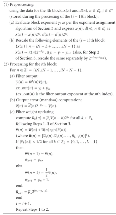
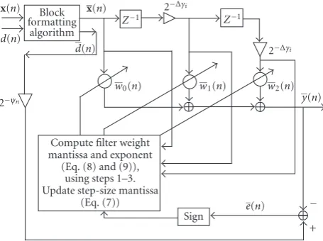
The proposed BFP treatment to the sign LMS algorithm is summarized inTable 1. The three units, viz., (i) buffering, (ii) block formatting, and (iii) filtering and weight updating are actuallypipelined and their relative timing is shown in
Figure 1. Also, for the filtering and weight updating unit, the internal processing is illustrated inFigure 2.
Table1: Summary of the sign LMS algorithm realized in BFP for-mat (initial conditions:ψ0=0,|wk(0)|<1/2,k∈ZL,μ0=μ).
(1) Preprocessing:
using the data for theith block,x(n) andd(n),n∈Z
i,i∈Z+ (stored during the processing of the (i−1)th block).
(a) Evaluate block exponentγias per the exponent assignment algorithm ofSection 3and expressx(n),d(n),n∈Z
ias
x(n)=x(n)2γi,d(n)=d(n)2γi.
(b) Rescale the following elements of the (i−1)th block:
{x(n)|n=iN−L+ 1,. . .,iN−1}as x(n)→x(n)2−Δγi,Δγ
i=γi−γi−1(also, forStep 2
ofSection 3, rescale the same separately by 2−Δγi+Smin).
(2) Processing for theith block: Forn∈Z
i = {iN,iN+ 1,. . .,iN+N−1}. (a) Filter output:
y(n)=wt(n)x(n), ex out(n)=γi+ψn
(ex out(n) is the filter output exponent at thenth index). (b) Output error (mantissa) computation:
e(n)=d(n)2−ψn−y(n).
(c) Filter weight updating:
computeuk(n)=μnx(n−k)2γifor allk∈ZL following Steps1–3ofSection 3.
v(n)=w(n) +u(n) sgn{e(n)}
(whereu(n)=[u0(n),u1(n),. . .,uL−1(n)]t).
If|vk(n)|<1/2 for allk∈ZL= {0, 1,. . .,L−1} then
w(n+ 1)=v(n), ψn+1=ψn, else
w(n+ 1)=12v(n),
ψn+1=ψn+ 1. end.
μn+1=μn2(ψn−ψn+1)
end i=i+ 1.
Repeat Steps1to2.
4. COMPLEXITY ISSUES
· · · Bu( fferring · · · ith block )
Bufferring ((i+ 1)th block)
· · ·
· · ·
· · ·
· · ·
· · ·
· · ·
· · ·
· · ·
BF ((i−1)th block)
BF (ith block)
BF ((i+ 1)th block)
· · ·
· · ·
· · ·
· · ·
Filtering ((i−2)th block)
Filtering ((i−1)th block)
Filtering (ith block)
Time
Figure1: The relative timing of the three units (BF: block formatting).
and exponent addition. In other words, in FP, computation ofy(n) will require the following additional operations over the BFP-based realization: (a) 2Lshifts (assuming availability of single cycle barrel shifters), (b)LEC, and (c) 2L−1 EA. Similar advantages exist in weight updating also.Table 2 pro-vides a comparative account of the two approaches in terms of number of operations required per iteration. Note that the number of additional operations required under FP in-creases linearly with the filter lengthL. It is easy to verify from
Table 2that given a low cost, simple FxP processor with sin-gle cycle MAC and barrel shifter units, the proposed scheme is aboutthree times fasterthan an FP-based implementation, for moderately large values ofL.
5. SIMULATION AND FINITE PRECISION IMPLEMENTATION
The proposed scheme was implemented in finite precision in the context of a system identification problem. A system modelled by a 3-tap FIR filter was used to generate an output
y(n)= 0.7x(n) + 0.65x(n−1) + 0.25x(n−2) +v(n), with
v(n) andx(n) being the observation noise and the system in-put, respectively, with the following variances:σ2
v = 0.008,
σ2
x = 1. The varianceσ2y of y(n)(≡ d(n)) was found to be 0.935. To calculate the upper bound ofμ(= 2−exmax/2), the quantity M = {|x(n)|,|y(n)| | n ∈ Z}was calculated, as 1.99 max{σx,σy}, so as to contain about 95% of the samples ofx(n) andy(n). This gives rise to exmax =1 and thus the
upper bound ofμto be 0.25. Takingμ= 2−6, block length N = 20, and allocating 12 bits (1 + 11) for the mantissas and 4(1 + 3) bits for the exponents of both the data and the filter coefficients, the proposed scheme was implemented in VHDL. For this, the Xilinx ISE 7.1i software was used for a target device of Xilinx Virtex series FPGA XCV1000bg (speed grade 6). Details of this implementation like hardware re-quirement, respective gate counts, and execution times are provided later in this section. Here we study the finite pre-cision effects by plotting the learning curves for this as well as for an FP-based realization under same precision for both the exponent and the mantissa. The learning curves, shown inFigure 3by solid and dashed lines, respectively, demon-strate that both these implementations have similar rates of
Block formatting
algorithm
Compute filter weight mantissa and exponent
(Eq. (8) and (9)), using steps 1–3. Update step-size mantissa
(Eq. (7))
Sign
x(n)
d(n)
d(n)
x(n)
Z−1 Z−1
2−Δγi
2−Δγi
w2(n)
w1(n)
w0(n)
y(n)
−
+
e(n) 2−ψn
Figure2: The proposed sign-LMS-based adaptive filter in BFP for-mat. The shifting ofx(n−k),k =1, 2 by 2−Δγiis done only at the
starting index of each block, that is, atn=iN,i∈Z+.
Table2: A comparison between the BFP vis-`a-vis the FP-based real-izations of the sign LMS algorithm. Number of operations required per iteration for (a) weight updating and (b) filtering is given.
(a) MAC Shift Magnitude check
Exponent comparison
Exponent addition
BFP L L+ 3 L Nil 1
FP L 2L Nil L 2L
(b) MAC Shift Exponent
comparison
Exponent addition
BFP L Nil Nil 1
FP L 2L L 2L
0 0.2 0.4 0.6 0.8 1 1.2 1.4 1.6 1.8 2
E
[
|
e
(
n
)
|
2]
50 100 150 200 250 300 350 400 Number of iterationsn
Figure3: Learning curves for the finite precision implementation of (a) the proposed Bbased scheme (solid line), and (b) an FP-based implementation (dashed line) with identical precision.
FPGA synthesis summary
The proposed scheme as well as the FP-based algorithm are implemented using basic hardware units like adder, multi-plier, register, multiplexer, shifter, and so forth. The step size
μ is taken to be a power of two as it eliminates the need of multiplier in the weight update loop. For the proposed scheme, the three stages, (a) buffering, (b) block format-ting, and (c) filtering and weight updating have the following hardware requirements.
(a)Buffering: this stage usesN16 bit registers, whereNis the block length (N=20 for the example considered).
(b) Block formatting: this stage first computes emax =
max{(el−nL) | l = 0, 1,. . .,N −1}(seeAlgorithm 1) by employing a 4 bit subtractor, a 4 bit comparator, and a 4 bit register for eachl,l=0, 1,. . .,N−1. One 4 bit adder is used next to compute the block exponentemax+Si. Then, for each
l,l=0, 1,. . .,N−1,emax+Si−elis computed by using one 4 bit subtractor and thelth data mantissa is shifted left/right byemax+Si−elusing two 12 bit shifters. The block formatted mantissas are finally stored inN12 bit registers.
(c)Filtering and weight updating: for filtering, a MAC op-eration (FxP) is used iteratively Ltimes whereLis the fil-ter order (L = 3 for the example considered). The MAC unit requires one 12×12 multiplier, one 24 bit adder, and two 24 bit registers, one for holding the result of multipli-cation and the other for storing the MAC output. This is fol-lowed by computation of output error mantissa that uses one 12 bit shifter and one 12 bit subtractor. For updating each tap weight, first note that sinceμ is a power of 2, that is,
μ=μ0 =2s(say), we haveμn=2sn wheresn=s−ψn. For updatingμn, it is then enough to updatesn, which requires a 4 bit subtractor and a 4 bit register, but does not require the shifter implied in the general update relation (7). The Steps1–3ofSection 3also get simplified, as it is then suf-ficient to use two 4 bit adders and one 4 bit register to
com-putesn+ exi+Smin, 2L12 bit shifters to shiftx(n−k),k∈ZL left/right bysn+ exi+SminandL12 bit adders/subtractors to
evaluatev(n) as per (6). Finally, to realize the update rela-tions (8) and (9), we need a 4 bit adder and a 4 bit register to updateψn, andL12 bit shifters as well asL12 bit registers to computew(n).
An FP-based realization, on the other hand, has only two operations, namely, filtering and weight updating, both re-quiring FP addition and multiplication. If two FP numbers havingrbit mantissa andmbit exponent each are multiplied, we need oner×rmultiplier, onembit adder, and two reg-isters of lengthmbits and 2rbits. If, on the other hand, the two numbers are added, we need onembit comparator, one
mbit subtractor, tworbit shifters, tworbit 2 : 1 MUX, one
rbit adder and for renormalization of the result, tworbit shifters and onembit adder/subtractor. We also need regis-ters of lengthmbits andrbits for storing the mantissa and exponent of the result of addition. To realize the filtering operation, an FP-based MAC operation is used iterativelyL
times that uses one FP multiplication withr =12 andm=4, and an FP addition withr =24 andm=4. For computing the output error, an FP addition withr =12 andm=4 is deployed. For updating each weight, a 4 bit adder is used to add the exponents of the step size and data, followed by an FP addition withr=12 andm=4.
The total equivalent gate count for the proposed scheme withN = 20 was found to be 9227, while the same for an FP-based implementation was 12,468. The minimum clock period needed for the FP-based implementation has been 16.052 ns. For the proposed scheme, minimum clock peri-ods required for the three stages, (a) buffering, (b) block formatting, and (c) filtering and weight updating have been 0.232 ns, 4.575 ns, and 6.695 ns. In other words, the mini-mum clock period needed for the proposed scheme has been 6.695 ns and thus the BFP realization is about 2.39 times faster than the FP-based realization, which also conforms to our observation fromTable 2forL=3.
6. CONCLUSION
The sign LMS algorithm is presented in a BFP framework that ensures simple FxP-based operations in most of the computations while maintaining an FP-like wide dynamic range via a block exponent. The proposed scheme is partic-ularly useful for custom implementations on ASIC or FPGA, where hardware and power efficiency constitute an impor-tant factor. For identical resource constraints, the proposed scheme achieves a speed-up in the range of 2 : 1 to 3 : 1 over an FP-based implementation, as observed both from oper-ational counts and also from a custom implementation on FPGA. Finite precision-based simulations also did not show up any noticeable difference in the convergence characteris-tics, as one moves from the FP to the BFP format.
ACKNOWLEDGMENT
REFERENCES
[1] K. R. Ralev and P. H. Bauer, “Realization of block floating-point digital filters and application to block implementations,”
IEEE Transactions on Signal Processing, vol. 47, no. 4, pp. 1076– 1086, 1999.
[2] S. Sridharan, “Implementation of state-space digital filter structures using block floating-point arithmetic,” in Proceed-ings of IEEE International Conference on Acoustics, Speech and Signal Processing (ICASSP ’87), pp. 908–911, Dallas, Tex, USA, April 1987.
[3] K. Kallioj¨arvi and J. Astola, “Roundofferrors in block-float-ing-point systems,” IEEE Transactions on Signal Processing, vol. 44, no. 4, pp. 783–790, 1996.
[4] S. Sridharan and G. Dickman, “Block floating-point imple-mentation of digital filters using the DSP56000,” Microproces-sors and Microsystems, vol. 12, no. 6, pp. 299–308, 1988. [5] S. Sridharan and D. Williamson, “Implementation of
high-order direct-form digital filter structures,”IEEE Transactions on Circuits and Systems, vol. 33, no. 8, pp. 818–822, 1986. [6] F. J. Taylor, “Block floating-point distributed filters,” IEEE
Transactions on Circuits and Systems, vol. 31, no. 3, pp. 300– 304, 1984.
[7] A. Mitra, M. Chakraborty, and H. Sakai, “A block floating-point treatment to the LMS algorithm: efficient realization and a roundofferror analysis,”IEEE Transactions on Signal Process-ing, vol. 53, no. 12, pp. 4536–4544, 2005.
[8] A. Mitra and M. Chakraborty, “The NLMS algorithm in block floating-point format,”IEEE Signal Processing Letters, vol. 11, no. 3, pp. 301–304, 2004.
[9] A. C. Erickson and B. S. Fagin, “Calculating the FHT in hard-ware,”IEEE Transactions on Signal Processing, vol. 40, no. 6, pp. 1341–1353, 1992.
[10] D. Elam and C. Lovescu, “A block floating point implemen-tation for an N-point FFT on the TMS320C55X DSP,” Appli-cation Report SPRA948, Texas Instruments, Dallas, Tex, USA, September 2003.
[11] E. Bidet, D. Castelain, C. Joanblanq, and P. Senn, “A fast single-chip implementation of 8192 complex point FFT,”IEEE Jour-nal of Solid-State Circuits, vol. 30, no. 3, pp. 300–305, 1995. [12] M. Chakraborty and A. Mitra, “A block floating-point
realiza-tion of the gradient adaptive lattice filter,”IEEE Signal Process-ing Letters, vol. 12, no. 4, pp. 265–268, 2005.
[13] B. Farhang-Boroujeny,Adaptive Filters—Theory and Applica-tion, John Wiley & Sons, Chichester, UK, 1998.
Mrityunjoy Chakrabortyobtained Bache-lor of engineering from Jadavpur univer-sity, Calcutta, in electronics and telecom-munication engineering (1983), followed by Master of Technology and Ph.D. de-grees both in electrical engineering from IIT, Kanpur (1985) and IIT, Delhi (1994), respectively. He joined IIT, Kharagpur, as a faculty member in 1994, where he currently holds the position of a Professor in
electron-ics and electrical communication engineering. The teaching and research interests of him are in digital and adaptive signal process-ing, including algorithm, architecture and implementation, VLSI signal processing, and DSP applications in wireless communica-tions. In these areas, he has supervised several graduate theses, car-ried out independent research, and has several well-cited publica-tions. He has been an Associate Editor of the IEEE Transactions
on Circuits and Systems I during 2004–2005 and also during 2006– 2007, he is a Guest Editor for an upcoming special issue of the EURASIP JASP ondistributed space time systems, has been in the technical committee of many top-ranking international confer-ences, and has visited many well-known universities overseas on invitation. He is a fellow of the IETE and a Senior Member of IEEE.
Rafiahamed Shaik was born in Mogallur, India, in 1970. He received the B.Tech. and M.Tech. degrees from Sri Venkateswara University, Tirupati, India, in 1991 and 1993, respectively. He is currently working towards the Ph.D. degree at the Indian Insti-tute of Technology, Kharagpur, India, all in electronics and communication engineer-ing. From 1993 to 1995, he has been a fac-ulty member at Deccan College of
Engi-neering and Technology, Hyderabad, India, and from 1995 to 2003 at Bapatla Engineering College, Bapatla, India. His teaching and re-search interests are in digital and adaptive signal processing, signal processing for communication, microprocessor-based system de-sign, and VLSI signal processing.
Moon Ho Lee received the Ph.D. degrees in electronic engineering from the Chon-nam National University, Korea (1984) and the University of Tokyo, Japan (1990). From 1970 to 1980, he was a Chief Engineer with Namyang Moonhwa Broadcasting Corp., Korea. Since 1980, he has been a Professor with the Department of Information and Communication at Chonbuk National Uni-versity. From 1985 to 1986, he was also with