Technical Memo No.
12
LARCApril 2 J 1958
Publications Engineering Dept.
J. Wolfram
AN INTROWCTION TO THE LARC®
DATA-PROCESSING SYSTEM
TABLE OF CONTENTS
Section Title ~
I INTRODUCTION
1-1
1.1
General1-1
1.2
Computer and Processor1-1
1·3
Storage1-1
1.4
On-line Input-Output1-2
1·5
Off-line Auxiliary Equipment1-3
1.6
Modular Construction1-3
1·1
Training and Reference Material1-3
II COMPUTER
2-1
2.1
General2-1
2.2
Instructions2-1
2·3
Instruction Overlapping2-2
2.4
Executive Command of the Processor2-2
2·5
Multipurpose Fast Registers2-3
2.6
Tracing Mode2-4
2·1
Sense Flip-Flops2-4
2.8
Error Checking2-4
2·9
Contingency Checking2-6
III PROCESSOR
3-1
3·1
Function3-1
3·2
Central Processor3-2
3·3
Synchronizers3-4
3.4
Dispatcher3-5
3·5
Processor Control Program3-6
APPENDIXES
Appendix Title ~
A COMPUTER INSTRUCTIONS AND WORD FORMATS A-l
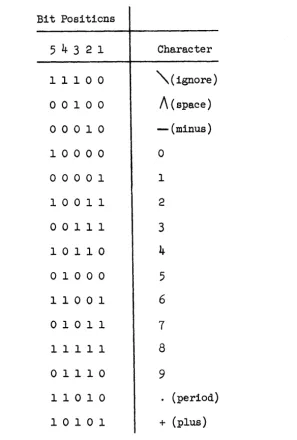
B CHARACTER CODES B-1
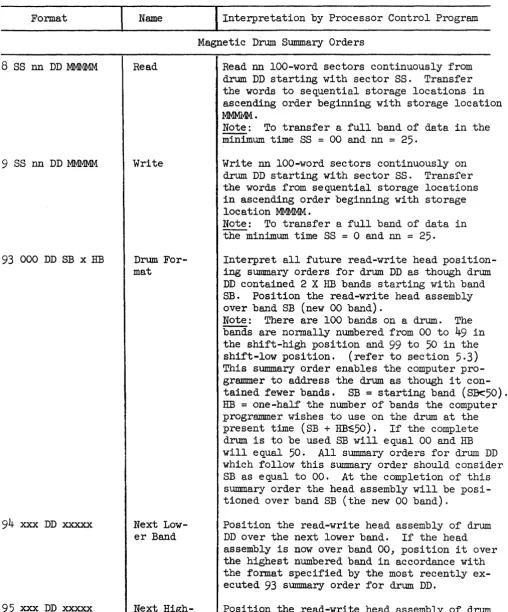
C SUMMARY ORDERS FOR A PROCESSOR PROGRAM C-l
D ARITHMETIC AND RELATED PROCESSOR INSTRUCTIONS D-1
TABLES
Table Title ~
1-1 MOIlJLAR UNITS OF EQUIPMENT IN A TYPICAL BASIC AND 1-5 A COMPLETELY EXPANDED LARC SYSTEM
2-1 REPRESENTATIVE COMPUTER INSTRUCTION TIMES IN 2-1 MICROSECONDS
A-l COMPUTER INSTRUCTIONS A-6
B-1 LARC ONE-DIGIT NUMERIC CODE B-2
B-2 COMPARISON OF LARC CHARACTER CODES B-5
C-l SUMMARY ORDERS
c-4
D-l ARITHMETIC AND RELATED PROCESSOR INSTRUCTIONS D-3
ILLUSTRATIONS
Figure Title ~
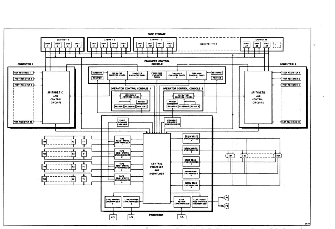
1-1 SIMPLIFIED BLOCK DIAGRAM OF A COMPLETELY EXPANDED 1-7 LARC DATA-PROCESSING SYSTEM
2-1 SIMPLIFIED TIMING DIAGRAM OF A SEQUENCE OF FOUR- 2-7 MICROSECOND COY~R INSTRUCTIONS
SECTION I
INTRODUCTION
1.1 GENERAL
The
LAR~intergrated
general-purpose data-processing system is designed by the Remington Rand Univac Division of Sperry Rand Corporation to solve a variety of problems, especially those beyond the range of current data-processing systems. Although the LARC system is expected to be used primarily in the fields of science and engineering, it is also adaptable for the solution of business problems. The system is provided with a complete set of programming aids, including automatic programming.1.2 COMPUTER AND PROCESSOR
A basic LARC system contains a computer and a processor, each of which has most of the attributes of a general purpose computer but performs somewhat specialized functions in the system. The primary function of the processor is the flexible, parallel, and coordinated control of all input-output operations and transfers between the auxiliary and the main storage. The computer is
designed to perform rapid arithmetic computation with a minimum of interference. If increased computing capacity is required, the basic system may be expanded readily to include a second computer. The computers and the processor are controlled by separate programs.
The two computers in an expanded system can be programmed and controlled to solve jointly a single problem or each can solve independently one or more separate problems. The processor is designed to take care of the input-output and auxiliary storage needs of both computers and to do any necessary editing of output data. If input-output demands are not excessive, it may be used to run a sorting, merging or almost any other type of side routine simultaneously with and independent of the computer programs.
1.3 STORAGE
There are four levels of storage in the LARC system which differ in speed, capacity, and costs.
The first level of storage is represented by flexible multipurpose fast registers contained within the computer. These registers are composed of tape-wound magnetic cores having a read-regenerate or clear-write cycle of one
micro-second. They are used interchangeably as accumulator registers for storing operands and results in arithmetic operations or as index (B) registers for stor-ing constants used in address indexstor-ing operations. Up to
99
12-digit fastregisters may be included in each computer.
The second level of storage is a magnetic ferrite-core storage which has a nominal read-regenerate or clear-write cycle of four microseconds. The ferrite-core storage, accessable to both the computer and processor, serves as the main storage of the system and as a common communication link ~ong the computers, the
processor, the auxiliary storage, and the input-output units. To increase the rate at which reference may be made to the main storage, it is divided into independently-operating modules. Since the computers and the processor have access to the same storage, practically any degree of interchange can be achieved among them by alerting one another to the presence of information in a particular part of the storage or by one causing the other to transfer control to a new sequence of instructions in the storage. Up to 97,500 l2-digit words of ferrite-core storage may be included in the system.
The third level of storage consists of magnetic drums. The drums are used to replenish the main memory and therefore have a sufficiently high trans-fer rate and capacity to keep abreast of the unusually high computing rates of the system. Data can be transferred between the main storage and the drums (with a single synchronizer) at a continuous rate of more than 330,000 decimal digits per second. A maximum of six million 12-digit words of drum storage may be in-cluded in a system.
The fourth level of storage consists of magnetic tape units which have a data transfer rate of 20,000 alphanumeric characters per second and a virtually unlimited capacity. Although the tape units may be used as relatively long-term storage, they are more often used in the
LARe
system as fast input-output.The magnetic drums are controlled by the processor program and, indirectly, by the computer program in much the same way as the input-output equipment. There-fore, to simplify the description of the computer and processor which follows, the drums are classed as input-output although they are actually a type of storage.
1.4
ON-LINE INPUT-OUTPUT
A full complement of both on-line and off-line input-output equipment can be provided with the system. The on-line equipment consists of:
(1) Magnetic tape read-write units for the fast introduction of data into the system and the fast recording of output for subsequent conversion on an auxiliary device or for long-term storage.
(2)
An
electronic page printer which employs a cathode ray tube for direct, fast recording of output data in either tabular or graphical form. The printer can represent output data as numeric or alphanumeric characters in an edited or unedited format, or as plotted curves complete with callouts, titles, scales, and grid patterns.(3) Electro-mechanical line printers for multiple-copy printing,
a line at a time, of numeric or alphanumeric data in an edited or unedited format. (4)
A
card reader for introducing data into the system directly from punched cards.1. 5 OFF-LINE AUXILIARY EQUliMENT
The off-line auxiliary equipment that can be provided with the system includes:
( 1) The Univac High-Speed Printer for printing in an edited format data recorded on magnetic tape.
(2) The Unityper II for direct keyboard recording of data on magnetic tape.
(3) The Tape Verifier for direct keyboard recording of data on magnetic tape or verification and correction of data already recorded on magnetic tape.
(4) The Punched Card to Magnetic Tape Converter.
( 5) The Magnetic Tape to Punched Card Converter.
( 6) The Paper Tape to Magnetic Tape Converter.
(7) The Magnetic Tape to Paper Tape Converter.
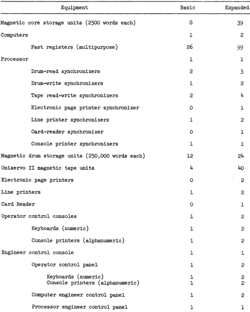
1.6 MODULAR CONSTRUCTION
The LARC system consists of modular units, ranging from solid-state com-ponent packages to input-output units, storage units, and complex computer units, which can be joined in various numbers and combinations to form a balanced system for a particular range of problems. The types and number of modular units of equipment that can be included in an expanded LARC system and that are included in a typical basic system, are listed in table l-i~H' A simplified block dia-gram of the completely expanded system is shown in figure 1.1. With the
exception of the core storage, which must be added to the system in units of four, single units may be added to a system up to the maximum allowed for expansion.
Each cabinet within the system contains its own power supplies, clock pulse generators, and heat exchangers. The synchronizers are modular units of control in the form of solid-state component packages contained within the pro-cessor cabinet which has the potential for accepting all of the synchronizers in the expanded system. Identical units of the system are functionally interchange-able and are designed for off line maintenance while the remainder of the system is operational.
1.7 TRAINING AND REFERENCE MATERIAL
The following training and reference material will be available with the LARC system:
(1) Operator Manual - normal procedures for starting and operating the system.
(2) Programming Manual - descriptions of computer and processor instructions, instructions conventions, programming and debugging techinques,
a standard processor program, standard error and contingency routines, and miscellaneous service routines.
(3) Automatic Programming Manual - a description of an automatic program compiler provided with the system and instructions for its application, modification, and expansion.
(4)
Maintenance Manual - troubleshooting and maintenance procedures, servicing schedules, and diagnostic routines for the computer, the processor, and the system as a whole. Detailed information for off-line maintenance of input, output, and storage devices is in the individual manual for each device.(5) Instruction and Operation Analysis Manual - an easily-referenced analysis and brief description of computer and processor instructions and opera-tions. Each instruction and operation is traced through the steps of its execution with a description in shorthand notation of signal functions and timing.
(6) Service Data Manual - a compilation of waveforms, data on voltages, and other service data in easily referenced form.
(1)
Circuit Manual - a functional description of standard circuit modules in the computer, processor, and storage and non-standard circuits inthe computer and processor.
(8) Logic Manuals - separate manuals for the computer and processor describing their logic circuits and the operations they perform, illustrated wi th truth tables, block diagrams, timing diagrams, and simplified logic diagrams.
(9) Control Console Manual - a description of the controls and in-dicators on the operator and engineer control consoles together with an analysis of the effect each control produces within the system, and information on the maintenance of the consoles themselves.
(10) Core Storage Manual - a physical and functional description of the core storage including non-standard circuits (Standard circuits modules are described in the circuit manual for the complete system), information and procedures for off-line testing, troubleshooting, and maintenance.
(11) Input, Output and Drum Storage Manuals - separate manuals
for each of the input-output devices and the drum storage. Each manual contains a physical and functional description of the device and information and procedures for off-line testing, troubleshooting, and maintenance.
(12) Parts Lists - an identification of parts for replacement purposes.
Table 1-1
Modular Units of Equipment in a Typical Basic and a Completely Expanded LARC System
Equipment Basic Expanded
Magnetic core storage units (2500 words each) 8 39
Computers 1 2
Fast registers (multipurpose) 26 99
Processor 1 1
Drum-read synchronizers 2 3
Drum-write synchronizers 1 2
Tape read-write synchronizers 2 4
Electronic page printer synchronizer 0 1
Line printer synchronizers 1 2
Card-reader synchronizer 0 1
Console printer synchronizers 1 1
Magnetic drum storage units (250,000 words each) 12 24
Uniservo II magnetic tape units 4
40
Electronic page printers 0 2
Line printers 1 2
Card Reader 0 1
Operator control consoles 1 2
Keyboards (numeric) 1 2
Console printers (alphanumeric) 1 2
Engineer control console 1 1
Operator control panel 1 2
Keyboards (numeric) 1 2
Console printers (alphanumeric) 1 2
Computer engineer control panel 1 2
Processor engineer control panel 1 1
---~
~··~wl
~~'~~llw~r~wl
,,,II.n, • T • •W
~.~ r--~
I
~ J" J. r= S,'·,
L_ - "
--
--
- --_RCON~
_ T E R I CONSOLE COIIPIITER 2
I I
F"" III" n.1 f I---- .Ey ... ... r..
I
eO_T,. PQCU • • c .... n.I
OPIuna IUIQAID 1---1 FAST 1t(,.STU f CCJlilflOL PAHfl. , ... ,,,n.,.1EI. ,,,.'NKI £.II.I~P".1:1. ClMnIOL PANELFAIT 1If"STEI 11--- ,,"E.
.
,
.
_L • 'I.TEI I---t fAST "(6IJTU 2'AST ""15ft1t J_ J--- I----L ".ST IIG'ITEI 3
I I ClPERATOR ~ c:qtIICIL£ I _TOR ~ c:qtIICIL£ Z I I
I I A'IITHMET·IC ARITHMET'C I I
I I
Or-IUT • • .
r-
f-~ CO.o:i:~T::IlEL I II I AND tOJllTttOL MNIL ~ 'ND I I
I I COHTROL
r-I
IE] ~J---J
CONTROL I II I CIRCUITS CI.CUITS I I
I I
)Rr.· .. ·II.'actAIlOjl ... • .. T£. N'IIT'·IIM'l8MltDIIRt:AD'1 I I
I I I I
I I I I
I I I I
I I I I
I I I I
" •• , 1'6'ITEI •
Ie----~
IIIW'.ri
-'·1
----t"AIT IUISTI."~l
"t""R...
,"IC .... OZ ••I$L
---1$1
$
....
~t= ~,D.U ,rNCHIIOff' .... "ttJ HlltrAD-W'TI: SYNC.-zrl ' I•
$
~I-"' .. _I$~-- ----~$
... t=
1~lZfll~
H! ... -..
IT& ~--- S'JlCNIONIZh z H.
~,_.I
..
J---~$
$
CENTRAL S . . .-.ouR$~--- uaa ...
... t=
TI. • I H'YC"-;-II11t PllDUSSOR----
-
~,-.... L$
DISP.TCHER s'*-:-az,a.1-$~-- ----~$ H,lr.~'""1
.- .t=
--I"
-- --- 4
--t .. ., ...
L"NC~'wtJ.
~
~
I,Ll. -' ..
SWIC ... ZI. IW'U.~~
5Y1C"""UI •1,
51'...
. " . ,c...
J
1:£L[<rOMIC PIlE PIC'N'E1I ~ ~srIICII ....
l.I.
••
8 8
--
0
SECTION II
COMPUTER
2.1 GENERAL
The computer is designed to rapidly and economically perform fixed or floating point arithmetic operations in single or double precision. To accom-plish this, as many operations as possible are performed automatically and in parallel. Means are provided to automatically: modify references to the stor-age by the instructions, control program loops, trace programs, and monitor machine and program errors. Not only are the bits and digits of a computer word transferred and operated upon in parallel but practically all secondary operations such as input, output, storage transfer, address modification, floating point, and error checking, which might take time from the cardinal arithmetic operations, are performed in parallel with the arithmetic operations.
2.2 INSTRUCTIONS
The computer has a repertory of some 75 instructions. Many of the instruc-tions are in the nature of variants on other instrucinstruc-tions. Their inclusion pro-vides the programmer (or more likely the compiler) with a wide choice of altern-atives to suit the requirements of a particular problem and increases the speed of computation by enabling operations to be performed with fewer instructions than would otherwise be required. To facilitate programming, the instructions have been made as straightforward as possible. Any oddities in the instructions or illogical restrictions on their use have been avoided.
Many of the instructions are in effect, small built-in subroutines. By de-signing into the instructions operations which formerly had to be programmed, much more of the computer program and the efforts of the programmer can be devoted to furthering the computations at hand rather than to organizing the computations or the program itself.
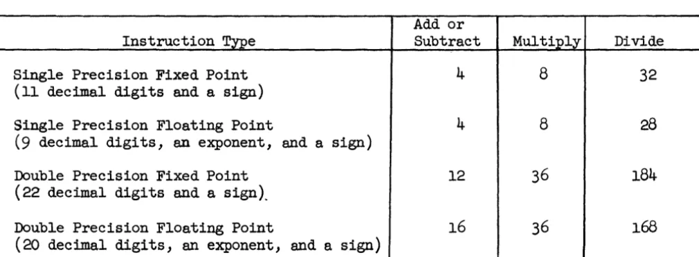
Performance times for representive arithmetic instructions of the computer are given in table 2-1. The instruction times listed are all inclusive and include the time required for storage access, address modification, error checking, etc. Also, all input, output, and auxiliary storage operations may be assumed to be performed in parallel with the instructions. For a complete list of computer in-structions and descriptions of computer word formats refer to appendix A. A description of the character codes used in the LARC system is given in appendix B.
Table 2-1. Representative Instruction Times in Microseconds
Add or
Instruction'!'n>e Subtract Multiply Divide
Single Precision Fixed Point
4
8
32
(11 decimal digits and a sign)
Single Precision Floating Point
4
8
28
(9 decimal digits, an exponent, and a sign)
Double Precision Fixed Point
12
36
184
(22
decimal digits and a sign),.Double Precision Floating Point
16
36
168
(20
dec imal digi ts, an exponent, and a sign)2.3 INSTRUCTION OVERLAPPING
To increase the rate of performing instructions without also increasing the amount of equipment in the computer to unreliable and uneconomical proportions,
the computer is designed to perform different steps of several instructions in parallel. While one instruction is being executed, an operand for a second
in-struction is being transferred to or from storage, the operand address for a third instruction is being modified, and a fourth instruction is being obtained from storage. This is illustrated in figure 2-1 which shows a simplified timing diagram for
a
series of addition instructions. Although any single add instruc-tion actually takes considerably more than four microseconds to perform, a series of these instructions is executed at a rate of one every four microseconds and for practical purposes the total instruction time is considered to be four micro-seconds. If a transfer of control to a new sequence of instructions occurs, the first instruction of the new sequence reqUires time to propagate through the several steps before it is executed. Therefore, whenever a transfer of control takes place, eight microseconds is added to the execution time of the instruction that caused the transfer. This time has already been added to the execution times of the transfer of control instructions listed in appendix A.The technique of overlapping instructions in the computer might upon rare occasions result in a conflict. For example, the results of one instruction might not be available in time if it is required for a beginning step of the next in-struction in line for processing. However, such conflicts are resolved automati-cally by control circuits within the computer.
It should be noted that the timing diagram (figure 2-1) is simplified and serves only to illustrate the technique of overlapping the processing of instruc-tions. Operations not indicated in figure 2-1, such as floating point calcula-tions and error checking, are performed in parallel with the operacalcula-tions shown.
Two of the steps that are overlapped are, obtaining instructions from stor-age and transferring operands to or from storstor-age. Overlapping these operations requires only that the instructions and operands be assigned to different areas (different units) of the core storage, a requirement that is usually satisfied as a matter of course in any system.
2.4 EXECUTIVE COMMAND OF THE PROCESSOR
The order code of the computer does not include instructions for directly controlling input-output operations. All such operations are handled remotely by the processor under executive command by the computer. Consequently, the com-puter is free to devote substantially all of its time to performing arithmetic operations. Input, output, and (optionally) editing commands may be summarized by the computer in well-defined pseudo orders (summary orders) having adjustable parameters and issued to the processor singly or in groups via the core storage. The computer program is required only to place the summary orders in the storage, alert the processor to their presence, and check for their completion after
appendix C. The processor can even be programmed to relieve the computer pro-gram of the task of generating and issuing summary orders and, in fact, relieve it of all concern with input-output operations so that computer time can be de-voted exclusively to arithmetic and related logical operations. In any case, the computer programmer will be concerned, not with the details of the input-output operations, but with problems of anticipating storage requirements, al-locating storage, and directing on a wholesale basis the flow of data to and from the storage.
2.5
MULTIPURPOSE FAST REGISTERS
Any computer instruction that contains an operand address may be tagged with an address of anyone of a number of index registers. Before such an in-struction is executed, its operand address will be modified automatically by the addition of a constant contained within the specified index register. Arithmetic instructions also contain the address of one of a number of accumulator registers which are used to store an operand involved in an instruction, or the result of
an instruction.
The index and accumulator registers are multipurpose fast registers logically interposed betweed the main core storage and the arithmetic system of the computer. They may be addressed and used interchangeably as index registers, as accumulator registers, or in the same way as a standard core storage location. The registers are composed of fast-switching tape-wound cores having a read-re-generate or clear-write cycle of one microsecond. By functioning as fast-access storage for operands and results in either arithmetic operations or address index-ing operations, they not only decrease the number of references to the slower main core storage but improve the flexible control of the arithmetic processes. Up to
99
of these multipurpose registers may be included in each computer. All other registers within the computer are non-addressable and ordinarily do not concern the programmer. These include the various control registers and registers within the arithmetic system for storing factors that are used during the actual execution of an arithmetic instruction.Iterative address modification techniques have been applied in the past only by sacrificing considerable computing time. Often .such techniques were used merely as a convenient way of exchanging computing time for storage space in fitting
a particular problem to the computer. The fast registers in the LARC computer not only enable the address modification operations to be completely overlapped with the execution time of the instruction but also enable extremely flexible control to be exercised over the iterative processes. An instruction may be tagged to refer to anyone of the fast registers for address modification or tagged so that it is not modified. Since a fast register that is used as an index register may also be used in the role of an accumulator register, its contents are subject to all of the arithmetic, test, and other instructions in the computer repertoire. In addition to this, special index instructions (appendix A) are provided which are, in effect, small subroutines for controlling the entry, reentry, and exit from the program loop using control information stored within the index register. A description of the format of the data stored in a fast register when it is used as an index register is given in appendix A.
In one sense, the computer is a single address computer, since each in-struction contains only one main storage address. However, anyone of a number of fast registers may be addressed and used by an instruction either as an accumulator
register or in the same way as a standard storage location. Furthermore, arith-metic instructions are available which take one operand from one fast register, another operand from the main storage (or another fast register) and place a re-sult in an adjacent fast register. In practical use these features enable the computer to be used much as a three-address computer. Quantities can be accumu-lated in several fast registers and combined without recourse to separate instruc-tions for returning intermediate partial results to the main storage. To use a very general example, the formation of quantities of the form ab + cd + ef can be effected with a minimum number of instructions.
2.6
TRACING MODEAny computer instruction may be tagged with anyone of nine tracing mode digits. Just before an instruction is executed, the tracing mode digit is de-tected. If the computer is operatingiin the designated tracing mode an automatic transfer of control will be effected to a routine associated with the tracing mode. At the completion of the routine, control is transferred back to the main program.
Instructions are available to direct the computer to enter or leave any one of the nine tracing modes by setting a tracing mode flip-flop. For example, when a set tracing mode flip-flop seven instruction is executed, all succeeding
instructions tagged with a tracing mode seven digit force a transfer of control to an associated routine. Ei ther the computer program, or the operator with a manual intervention routine, may at any time instruct the computer to enter or leave any of the nine tracing modes. The computer can therefore be directed to automatically trace its programs in several different modes or mode combinations for the purpose of debugging or monitoring a program or for the purpose of in-jecting side routines at various points in the program. A tracing mode routine can be designed to perform any number of functions. For example, it may be de-signed to prepare the contents of certain registers for print-out. Except for the instructions that are actually traced, no time is lost since the instructions to be traced are detected automatically by the computer circuits rather than by the program itself. No change has to be made in a program coded for a production run to enable tracing under a number of different conditions.
2.7 SENSE FLIP-FLOPS
The computer instruction code contains instructions for setting or re-setting any of ten sense flip-flops together with conditional transfer of control instructions that are dependent on the state of the sense flip-flops. The sense flip-flops have no predetermined function. Essentially, they are general-purpose single-bit storage units that the programmer may use in numerous ways. Like the tracing-mode flip-flops, the sense flip-flops may be set directly by the main program or through manual intervention by the operator. The sense flip-flops enable the program to change the paths it will follow through its own routines or the operator to modify the paths the program will follow. For example, a general program could be directed, by the operator or by the program itself, to perform a specific set of operations on the data for a particular run. 2.8 ERROR CHECKING
In many data-processing installations considerable computing time is
becomes more valuable. While a human ponders for a few seconds or manipulates
switches on a console, the computer can perform operations numbered in the millions. To prevent the loss of valuable computer time, an error occurring in the LARC system is detected automatically and, whenever possible, corrected without human inter-vention. If automatic correction proves impossible, the general source of the error is located and isolated from the system, and the exact cause of the error is pinpointed and corrected off line, thereby releasing the system for further computation.
The computer contains built-in checking oircuits, designed to detect all single-bit errors. The checking circuits are designed not only to detect an error but also to give an immediate indication of the specific area of the computer in which the error occurred. On the order of 20% of the circuitry in the LARC system is devoted to redundant circuits and associated checking circuits. It is estimated that these circuits double the utility of the system by quickly locating faults and by eliminating the need for programmed checks.
An error may be one of several types. It may be an error due to the complete failure of a component such as a transistor or resistor, in which case the faulty component would have to be located and replaced. It may be an error caused by a transient or intermittent fault which may occur only once or at widely separated intervals. In this case, it would be convenient to repeat the operation that caused the error and continue the program without further inter-ruption after obtaining an indication that the error has occurred and where it occurred. Then again, an error may be caused by an error in the program, for example, by an attempt to add a numeric combination or to decode a non-existant address or instruction. In this case it would be convenient for the programmer to obtain information which would aid him in detecting the error and correcting the program.
Should an error be detected in the computer, one or more error flip-flops are set to indicate the type of error and which, when set, cause an
immediate and automatic transfer of control of the computer to an error routine designed to handle the situation. Instructions are available for use in the error routines to test the various error flip-flops in order to localize the source of the error. Ordinarily the error routines will not change from problem to problem run on the computer. They are, however, subject to change and improvement by the programmer. Although the error routines may vary con-siderably in complexity, a typical routine may take the following general form.
When an error is detected, control is transferred to an instruction in a specific storage location which is the beginning of an error routine. The routine examines the error flip-flops to determine the type of error committed and then initiates a printout which would aid the maintenance engineer or pro-grammer in analyzing and correcting the error. The printout might contain the following information:
(1) The type of error (adder, index register, etc.). (2) The digit position at which the error occurred. (3) The time at which the error occurred.
(4) The instruction that caused the error.
(5) The storage address of the instruction that caused the error.
(6) The contents of the accumulator register or registers involved, if any.
(7) The contents of the index (B) register involved, if any.
(8) The operand involved.
If possible, the specific instruction that caused the error is then re-peated. If the instruction is a type that cannot be repeated, the routine transfers control to a rerun point in the program. In either case, if the error is not re-peated, indicating that it is transient or intermittent, the computer continues with the main program without any human intervention having occurred. However, the error is not neglected, since the printout constitutes a running log of all intermittent errors that have occurred, together with information as to their source and frequency. The maintenance engineer may analyze this information to determine what corrective action, if any, is necessary during the next convenient maintenance period.
If an error continues to repeat, indicating that a permanent fault or programming error has occurred, the computer stops. When the computer stops, the maintenance engineer or programmer is usually provided with enough information by means of the typeout or indicators on the engineers console to isolate
suffi-ciently the source of the error. At this point, the maintenance engineer might remove a group of printed circuit packages and replace them with pre-tested e qui valents • However, he may find it quicker and more convenient to call in a diagnostic routine from the drums or tapes to further isolate the error to one (or a very few) printed circuit package and replace it.
More elaborate error routines could be designed which would attempt to isolate the error source still further and perhaps print out the designations of the specific printed circuit packages that are to be replaced. However, such routines might not be justified by the frequency of occurrence of the errors.
2.9
CONTINGENCY CHECKINGThe computer contains checking circuits for detecting, not only machine errors, but overflow conditions within the arithmetic system and certain condi-tions reflecting mistakes in programming. These built-in circuits continuously and automatically check for the following conditions:
(1) Floating zero result-occurs on floating point add and subtract instructions when an arithmetic subtraction of two numbers with equal exponents produces a zero answer.
(2) Non-normalized divisor-occurs on floating point division
ins~ructions when the divisor has a zero in the most significant digit position (tre digi t position adjacent to the exponent).
(3) Exponent overflow-occurs on floating point add, subtract, multiply, and divide instructions when the addition, subtraction, multiplication, or division of two floating point numbers results in an exponent greater than
99.
(4)
Exponent underflow-occurs on floating point add, subtract, multiply, and divide instructions when the addition, subtraction, multiplication,or division of two floating point numbers results in an exponent less than 00; or on fixed-to-floating point or floating-to-fixed point conversion instructions which would cause a loss of significant digits.
(6) Program error in sign-occurs on all add, subtract, multiply, divide, negative transfer, and comparison instructions when the rules for the proper character in the sign position are not obeyed.
(7) Non-nor.malized mistake-occurs on floating point add or subtract instructions when an arithmetic subtraction involving a~l zero or non-normalized numbers produces the wrong answer.
If one of these conditions arises, it is handled in much the same way as an error condition. The computer automatically transfers control to a contingency routine specifically designed to handle the condition. The programmer decides beforehand exactly what should be done if a particular c cm.di tion is detected and designs the contingency routine for that condition accordingly. He may, for ex-ample, call for a printout to indicate that the condition has occurred but other-wise ignore the condition and return control to the main program; he may decide that the condition be corrected, if possible; or he may decide that the program is at fault and switch to a new program. In any event, the system need not be interrupted while human decisions are made or corrective action taken, and time-wasting programmed checks need not be made to detect contingencies.
MI CROSECONDS
I NSTR.UCTION STEP
1 2 1 3
1
4 5 \ 6 \ 7 \ 8, \10 \11
112
13114- \1sl
4~
17118
11.9 I 20 108TAIN INSTRUCTION FROU STORAGE
MODIF'( OPERAND
ADDRESS
TRANSFER OPE.RAND
TO OR FROM STORAGE
EXECUTE
I HSTRUCTION
In In+. 1n+2- In+s
'lij'///// ' / / / / / / / / / h
In -1 In In+1
In+2-1 / / / / / / / / / / / In+2-1 'lA
In-'l
In-:s :/,////h
In-~ In In+1
1 h r / / / / / / / h 'V////////h
I n-2. 1"-1 In
' l / / Y / / / / / / / / / / ' h
Fi9ure 2-1. Simplified llming Diagra.m of a. Sequence
of Four - Microsecond Computer I ns+rudions
2-7
In ....
I n +3
:/'/////////.I'lI
In+%. In+e
'l////h
In+1
In+1-'l///lj"/h
SECTION III PROCESSOR
3.1
FUNCTIONThe processor is a stored-program computer with many general-purpose characteristics. Its primary role in the LARC system is the coordinated and flexible control of concurrent input-output operations under summary command of the computer program.
The processor is programmed to pick up summary orders issued by the computer, acknowledge their issuance, interpret them, supervise their execution, and inform the computer of their completion. All this is controlled by a
fluid loop program that need not change for every program run on the computer. A flexible processor program for controlling input and output was developed along with the LARC system much as the equipment was developed and tested. In fact, the program, together with the general purpose computing abilities of the processor, is an alternative to using a multitude of costly and in-flexible built-in control equipment to perform a similar function.
An important advantage to the programmed-control approach is that the programmer is given the ability to modify input-output control. As a programmer gains experience with the system he may take advantage of new programming
techniques and his own ingenuity to devise control programs for the processor which will without doubt improve the performance and even change the performance
characteristics of the processor probably in ways not even contemplated by the original designers.
The processor has enough speed and flexibility to handle the complete complement of input-output devices, operating many in parallel, and to service both computers in the expanded system. Its general purpose characteristics enable the system to be expanded with ease and molded to a customers require-ments without conflicting with previously designed computer programs.
When the processor is not being used to the limit of its ability in controlling input-output, as will often be the case, particularly in a one computer system, it can relieve the computer of additional tasks, such as the edi ting of output data and, if it still has extra time , it can perform a sorting, merging, compiling, or other side routine concurrently with and
entirely unrelated to a program being run on the computer. The work load can, in fact, be shared between the processor and the computer so that each does the type of work that it is most suited to do by virtue of its design.
Logically, the processor separates into three major divisions re-presenting different levels of control. The three major d1 visions are:
(1) The central processor. (2) The synchronizers.
3.2 CENTRAL PROCESSOR
The central processor is the general purpose computing section of the processor. Compared to the computer, it has much less elaborate facilities for performing arithmetic operations. The arithmetic system of the central processor consists of a serial adder-comparator and two connecting l2-digit shift registers for the temporary storage of operands. When an add instruction is executed, operands are shifted from the two registers into and through the adder a digit at a time. The result is shifted back into one of the registers, which also serves as an accumulator register. The bits and digits of a word are transferred between the registers and the main core storage completely in parallel.
The instruction cycle of the central processor is overlapped only to the extent that the access time for obtaining instructions from storage is overlapped with the execution time. Unlike in the computer, the execution time is not overlapped with the time required to transfer operands or perform
address modification. The central processor has no special facilities for address modification. The central processor contains the control circuits nor.mally found in most general-purpose computers together with somewhat more specialized control circuits to address, monitor, and exercise supervisory control over the synchronizers and the input-output devices.
Time Reference
The LARC system is designed to change over to a new problem without interruption. While computations are being performed on one problem, the next problem may be in the process of being loaded into the storage, while
results from a previous problem are being printed out, all of which is made possible by the parallel operation of the various units of the system.
To aid in a changeover, a real-time reference is provided in the central processor. The timing reference may be used, among other things, to determine when the time allotted for one program on the computer is exhausted so that an automatic changeover may be made to a new program. The timing source is a
60
cycle clock which continually alerts the processor program to keep a running count of the time of day. The computer can order the processor to keep a check on the running time of a program and after a specified period of time has passed direct the computer to a routine for affecting a changeover.An interesting use of the real-time clock is to time logical operations within the processor. The pr9cessor program uses the clock reference to time certain extra long logical operations, such as tape reversal operations on a tape unit or information displays on the operator console, thereby eliminating the need for costly fixed delay elements. Such a timing reference may be used for any number of other purposes, for example, to record the time at which errors or other events occur during the course of running programs. It is
particularly useful in scheduling problems on the system and in solving problems in real time.
Instructions
The central processor has an instruction code separate and distinct from that of the computer. It contains a complement of general-purpose instructions
(appendix D), such as add, subtract, shift, and transfer instructions, that are used in carrying out its primary editing, interpreting and supervisory functions, but which may also be used in executing a side program. The central processor does not however have instructions for multiplying and dividing since these in-structions are not required in the editing and control routines which carry out its primary functions. If multiplication or division is required in a processor program, it could be done by means of a subroutine. More likely it would be done by the processor temporarily interrupting the computer to do it. The central processor can set an intervention flip-flop in either computer which will force the computer to transfer control to a routine associated with the flip-flop. If required, the transfer can be programmed so the computer will return automatically after completing the routine to the point in its own program at which it was in-terrupted.
The central processor, although it performs arithmetic instructions at a slower rate than the computer, can perform in
16
microseconds an addition instruc-tion which takes an operand from storage, adds it to an operand in the accumulator register, and returns the result to storage.The majority of the central processor instructions are used to communicate with or control the error circuits, the input-output devices, the synchronizers,
and the dispatcher. Most of these instructions are one of the three general types listed below. Many can be addressed to anyone of several synchronizers or other devices.
(1) Set flip-flop instructions that alert a synchronizer or other device to perform a specific function, such as connect or read 100 words.
(2) Transfer instructions that transfer control information between the central processor accumulator register and the dispatcher or a synchronizer. The control information might specify the mode in which a synchronizer should op-erate or the first address of a storage area to which the dispatcher should trans-fer data for a particular synchronizer.
(3)
Test flip-flop instructions that are actually conditional trans-fer instructions conditional on the state of the flip-flop tested. These instructions are used by the central processor to monitor and test the condition of a synchronizer or other device, for example, to test the availability of a synchronizer or to test if a synchronizer or other device has completed a previously ordered operation.Input and output transfers for a side program of the central processor can be handled in much the same way as it is handled for the computer, by the same processor input-output control program that governs the performance of summary orders from the computer. The programmer therefore need word with a relatively few arithmetic-type instructions when producing a side routine and need not concern himself with a myriad of detailed input-output orders. Such orders would only be used if the programmer wished to modify or redesign a processor input-output control program.
3.3
SYNCRHONIZERSThe central processor does not have time to control every step of several input-output operation being performed in parallel. Consequently, much of the detailed and specialized work of controlling these operations is performed by the synchronizers. A synchronizer represents a modular grouping of logical circuits for controlling a particular reading or recording process. Its logical form depends to a great extent on the characteristics of the
reading or recording device with which it is associated. Physically the ·synchronizers are contained within the processor cabinet which has the
potential for accepting all of the synchronizers of the expanded system listed in Table
1-1.
3·3·1
FunctionThe synchronizers control the actual reading or recording process, and the translation and,the serial flow of information, digit by digit, between a bUffer register and an input-output device. In the process of transferring in-formation a synchronizer may perform such functions as synchronizing input information with the internal timing of the system, checking and counting the information for errors, or translating the information in one way or another.
Whereas a single summary order from the computer might call for the transfer of a block of several hundreds or even thousands of words, a single instruction by the central processor alerts the synchronizer to process a smaller block of words which is same fraction of the block specified by the summary order. The synchronizer is designed to process the smaller block automatically without direct intervention by the central processor. While one block of information is being processed, the central processor program mayor may not, based upon parameters defined in the summary order from the computer,
alert the synchronizer to process to next block of information. The actual instruction that alerts the synchronizer is executed by the central processor in four microseconds whereas the operation initiated in the synchronizer or other device by the instruction may take several milliseconds. Meanwhile, the central processor is free to continue processing other summary orders.
3·3.2
Communication with Central ProcessorWhenever a synchronizer or an input-output device completes an operation or action to a point where it is ready to accept further instruction from the central processor program it records this fact by setting a flip-flop. The cen-tral processor program tests the flip-flop with a conditional transfer instruc-tion to determine whether a synchronizer or other device requires atteninstruc-tion. If it is set when tested, control is transferred to a routine which determines what action to take and instructions the device accordingly.
Rather than waste time testing every flip-flop to find the one that is set, the central processor program short-cuts the testing by first performing a master test on all of the flip-flops and then a series of group tests. The testing is performed in an order of priority so that the flip-flops of the synchronizers that require the most frequent attention are tested first. In general, the frequency with which a synchronizer requires attention is a func-tion of its data transfer rate. Consequently the drum synchronizers which operate at the highest rate are tested first, then the tape synchronizers, etc. A synchronizer is designed to alert the central processor of its need for
in-struction sufficiently far in advance to give the central processor program time to complete any routine in which it happens to be engaged and satisfy any
requests for supervision by higher priority synchronizers. Any routine run on the central processor is required to perform the master test periodically to monitor the real-time operations of the synchronizers.
3.4
DISPATCHERThe dispatcher is a central exchange which controls the transfer of data between the buffer registers of the synchronizers and the main core storage. One to four one-word buffer registers for each synchronizer perform the serial-parallel conversions and store data preparatory to transferring it to the main storage or to an output device. Transfers between the buffer registers and the input-output devices are controlled by the synchronizers, and the rate and order of flow is governed primarily by the characteristics of the particular device con-cerned. Whenever a synchronizer completes the processing and transfer of a word to or from a buffer register, it signals the dispatcher to transfer the word to the main storage (if it is an input synchronizer) or to obtain a new word from storage (if it is an output synchronizer). To accomplish this, means must be available to the dispatcher for keeping track of the storage address of every word transferred. Therefore, a register is provided in the dispatcher for each synchronizer in which is stored the main storage address of the next word to be transferred to or from the buffer register of that synchronizer. The be-ginning storage address for a particular operation is supplied by the central processor from information derived from the summary order from the computer and the address is modified automatically each time the word it represents is trans-ferred. Whenever an address is read out of an address register and sent to the storage to initiate a transfer, it is also sent to a time-shared address modifier in the dispatcher where it is modified before being written back into the same register at the end of the transfer operation. The modified address is then the storage address of the next word to be transferred for the synchronizer.
Since the synchronizers process information asynchronously with respect to one another, several may require access to the storage at the same time.
Priority circuits are therefore contained within the dispatcher to define, on the basis of preassigned priority ratings, the time at which transfers are made for each synchronizer. The priority ratings, in general, reflect the rates at which the various synchronizers must have information transferred to maintain, without interruption, the flow of data required by the input-output device.
3.5
PROCESSOR CONTROL PROGRAMA list of summary orders that are accepted and executed by one control program designed for the processor are listed in Appendix C. The way in which the program receives and sequences the execution of the summary orders is described briefly below. The processor control program described here is a general-purpose program designed to be applicable with practically any type of program run on the computer. However, it does not by any means represent the most efficient method of controlling the input-output operations for any one type of computer program. Much more efficient processor programs can be compiled which, without receiving summary orders, execute the input-output operations independently, in an order and sequence compatible with the require-ments of the computer program being run. Such a processor program relieves the computer of the tasks of constructing and issuing summary orders and, at the same time, relieves the processor of the tasks of receiving, extracting, and interpreting the information summarized in the orders. Direct exchange between the computer and processor ordinarily would be limited to the computer at various pOints in its program alerting the processor to begin an extensive series of input-output operations in a predetermined sequence and the processor, in turn, alerting the computer to the completion of the series.
3·5·1
Summary OrdersThe summary orders listed in Appendix C are not instructions in the sense that they are decoded by a built-in decoder in the processor. Rather, they are in the form of a pseudo or program code interpreted by the processor program to generate actual central processor instructions which control the synchronizers and other devices in carrying out the summary orders. A summary order usually specifies a type of operation to be performed, the drum or
input-output device involved in the operation and parameters of the operation. For example, a tape summary order may specify that
250
blockettes of10
words each be read in a forward direction on tape unit15
and be transferred to consecutive storage locations beginning with storage location15,600.
3·5·2
Disclosure of Summary OrdersA computer program communicates with the processor by placing one or more such summary orders in sequential locations in the main storage and alerting the processor program to their presence by setting a disclosure flip-flop. A count of the number of summary orders in the group that call for a transfer of data to or from the main storage is contained in a word filed along with the summary orders. Whenever the processor program completes one of these summary orders, it lowers the count by one so that the computer program can check the
count for zero to determine that all required data transfers have been accomplished. As an alternative, the computer program can code the word containing the count
of summary orders in such a way that the processor program will be directed to interrupt the computer program and transfer computer control to a specified subroutine as soon as all the required data transfers are completed.
The central processor program, upon testing the disclosure flip-flop, is directed to a perdetermined storage location which contains a disclosure word (the first and last address of the summary orders), placed there by the computer, that defines the area of the storage in which the summary orders are stored. After picking up the information which defines the location of the summary orders, the processor program resets the disclosure flip-flop, thereby enabling the computer to issue another group of orders. Before issuing a new group, the computer program tests the disclosure flip-flop to ensure that the processor program has been alerted to the presence of the last group that was issued.
3·5·3
Execution of Summary OrdersThe processor program is designed to accept summary orders and execute them as rapidly as pOSSible, relieving the computer program of all concern
about the availability of the equipment needed to complete the summary orders. Once the processor program has been alerted to the presence of the summary orders, it examines and begins to execute each summary order in turn, provided all of the equipment that is needed to process the summary order is available. Delays in processing a summary order occur if:
(1) The central processor is temporarily tied up supervising operations already in progress.
(2) A drum, input-output device, or synchronizer that is needed to execute the summary order is busy performing a previously ordered operation.
(3)
The summary order calls for a transfer of data to or from the same area of main storage as a previously accepted summary order which is not yet completed.Should condition (2) or (3) exist, the processor program files the summary order and attempts to execute the next one.
To ensure their continuity, the processor program always gives priority to the control of operations already in progress. At least every
500 microseconds, the central processor program performs the master test to monitor and answer all requests for instruction by currently operating devices. Only if all requests for instruction by currently operating devices have been satisfied will the program accept for processing newly issued summary orders.
The processor program also keeps a conflict control file of all summary orders currently being executed or awaiting execution that call for a transfer of data to or from the main storage. As each new summary order is received, comparisons are made by the program to deter.mine if the order is in conflict in that it refers to the same storage area as an order in the conflict control file. If there is a conflict, then the program delays the execution of the summary order, even though the equipment needed to execute it is available, until any previously accepted summary order with which it is in conflict has been
completed. This prevents the possible premature destruction of data in the storage or the transfer of wrong data from the storage as a result of a summary order being executed out of sequence.
3 .6 ERROR CHECKING
The processor, like the computer, contains checking circuits throughout that are designed to detect all Single bit errors. An error in the central
processor is handled in somewhat the same manner as in the computer (paragraph
2.8) in that an error flip-flop is set causing an immediate and automatic transfer of control to an error routine which can test the error flip-flops and take appropriate action.
Should an error be detected in a synchronizer it is handled differently. Two flip-flops are set, one, which may be set by error-checldng circuits of a particular type in any synchronizer, indicates the type of error detected; the other, which is set only by the error-checking circuits of the one synchronizer, indicates which synchronizer detect an error. When the error flip-flops are set by the synchronizer, the central processor does not immediately transfer control to an error routine. However, the next time the central processor performs an instruction which alerts the synchronizer to process another block of data or to end an operation, the instruction will test the error flip-flop of the synchronizer to determine if an error was committed during the process-ing of the last block of data. Should the flip-flop be set when tested, the central processor will transfer control to an error routine.
The central processor has error test instructions which can be used in the error routine to deter.mine the type and location of the failure. It therefore can keep a running log of detected failures and, if possible, initiate a short rerun procedure. A rerun procedure in the processor may take the form of rereading a block of data from a magnetic tape. Instructions are provided the processor for setting the read-amplifier gain control of the tape units to nor.mal, high, or low gain. A block of data that cannot be read at nor.mal gain often can be salvaged, without human intervention, by rereading it at a different gain setting.
The checking circuits within the processor are designed to indicate whether an error originated within the logical circuits of the processor or within an external device (storage or input-output device). Often it is
SECTION IV
MAGNETIC CORE STORAGE
4.1 FUNCTION
The magnetic ferrite-core storage of the LARC system is the main storage for both computers and the processor and the common link through which they ex-change information. It is also used as a flexible buffer storage for blocks of data being transferred between the drums and input-output devices. Any area of the storage not being used for other purposes may be used as temporary buffer storage.
4.2 MODULAR CONSTRUCTION
The core storage is divided into modular units each of which has a capacity of 2500 words of 12 decimal digits. Four storage units are contained in a cabinet and the storage units may be added to a system in units of four up to a maximum of 39 units, the equivalent of 97,500 words. Each cabinet is self-contained. It has its own power supply, clock-pulse generator, and heat ex-changers. Because of a logical limitation on the number of storage addresses available for assignment, one cabinet in a completely expanded storage system of ten cabinets would contain only three 2500-word units. Although the core storage may be expanded to a capacity of 97,500 words, with the drum storage to back it up, less would ordinarily be required for most systems. For example, a system containing one computer that is being produced for the Livermore Atomic Research Center contains only eight core storage units with a total capacity of 20,000 words.
Each storage unit contains the switching, timing, and amplifying circuits required for independent operation. The division of the storage into units capable of independent operation enables simultaneous references to be made to the storage both by the computer, for obtaining instructions and for transferring operands, and by the processor, for instructions or data involved in carrying out its program and for transferring data to or from the input-output. It also enables off-line maintenance to be performed on a single unit while the others are operating. A plugboard is provided to functionally
inter-change the units, that is, inter-change the address assignments of the units.
4.3 TIMING
With the circuits used in the core storage a complete clear-write or read-regenerate cycle would normally take on the order of eight microseconds to complete. However, the allowable transfers to or from a single storage unit are increased to a rate of one word every four microseconds by designing the storage units so that the operations of selecting the proper cores and reading or clearing data from them are overlapped and performed in parallel with the operations of selecting the cores and writing or regenerating the data. As a result, the storage cycle is, for all practical purposes, four microseconds.
both the computers and the processor. The bus is time shared on the basis of a repetitive 4-microsecond time cycle which is broken down into eight one-half microsecond time intervals (time slots) during anyone of which one word of data can be transmitted to the storage in parallel. The time slots are ap-portioned to the various connecting areas of the computers and the processor in the following order.
<:---
4psec.---;>I~
Cl C2 P Not C2 Cl PI 0 D Used I 0 D
The abbreviations and their meanings are:
p
=
processor time slotCP
=
central processor; indicates the time slot on which the central processor section of the processor transfers operands or instruc-tions that are used in its program.D
=
dispatcher; indicates the time slots on which the dispatcher sec-tion of the processor transfers input-output or drum data for a synchronizer.CI
=
computer number I C2=
computer number 2I
=
Instruction; indicates the time slot on which a computer obtains an instruction.o
=
Operand; indicates the time slot on which a computer transfers operands.Each storage unit is independently timed so that it can begin its opera-ting cycle on any one of the time slots. Consequently, disregarding the one time slot that is not used, data may be transferred to or from different storage units at a maximumn rate of one word every one-half microsecond. Logical operations within the computer and the processor are timed so that the storage transfers
required in the performance of the operations coincide with the time slot allotted to the particular section of the computer or processor performing the operation. All instructions have been designed to require some multiple of four microseconds for their execution, so that their execution times are compatible with (in phase with) the four microsecond rate at which the instructions can be obtained from the storage. All data transferred over the bus system by either the I computers or the processor are checked for single bit errors per decimal digit by a single set of time-shared error checkers located in the processor. Error signals from the checkers are distributed to the sections of the system that originate the trans-fers over a separate set of time-shared buses.
4.4
INTERLOCKS
The LARC system ordinarily is programmed to avoid simultaneous reference to the same storage unit by two or more sections of the system (the computers, the central processor, or the dispatcher). However, occasions do arise in which su