United States Patent [191
Rudi
[54] METHOD AND ARRANGEMENT FOR
PRECISE POSITIONING OF A MAGNETIC HEAD TO VARIOUS TRACKS OF A MAGNETIC TAPE
Guttorm Rudi, F
jellhamar, Norway
[75] Inventor:
[73] Assignee: Tandberg Data A/S, Oslo, Norway
[21] Appl. No.: 135,375
[22] Filed:
Aug. 14, 1987
[30]
Foreign Application Priority Data
Dec. 22, 1986 [DE] Fed. Rep. of Germany ... .. 3644005
[51] Int. Cl.‘ ... .. G11B 5/56; GllB 5/55 [52] US. 01. ... .. 360/77.02; 360/75;
360/78.02; 360/74.1
[58] Field of Search ... .. 360/75-78,
360/106, 107, 109, 74.1, 77.12, 77.01, 78.02,
78.01
[56] References Cited
U.S. PATENT DOCUMENTSv 3,292,168 12/1966
3,541,270 11/1970
4,866,548
Sep. 12, 1989
Patent Number:
Date of Patent:
[11]
[45]
FOREIGN PATENT DOCUMENTS
59-185020 10/1984 Japan ... .. 360/78
OTHER PUBLICATIONS
Patent Abstracts of Japan, vol. 9, No. 48, (P388)
[1771], Feb. 28, 1985; & JP-A-59 185 020, (Sony KK),
20-10-1984.
IBM Technical Disclosure Bulletin, vol. 17, No. 1, Jun. 1974, pp. 217 and 218, Schwarz.
Patent Abstract of Japan, vol. 9, No. 83, (P-348), Apr. 12, 1985 8;- JP-A-59 213 070, (Sankivou Seiki Seisaku sho KK) 01-12-14 1984.
Primary Examiner-Alan Faber
Assistant Examiner-Steven R. Garland
Attorney, Agent, or Firm-Hill, Van Santen, Steadman &
Simpson ,
[57]
ABSTRACT
For precise positioning of a magnetic head to various tracks of a magnetic tape, deviations occur as a conse
quence of manufacturing tolerances of the magnetic
head, or as a consequence of the adjustment thereof.
Correction values are identi?ed wherein a read head
identi?es a center of a track recorded by a write head.
A moving direction of the magnetic tape is reversed and
the center of the track is identi?ed again. The read head
identi?es the center of a track recorded by a neighbor
ing write head. Positional values allocated to the center
of the tracks are subtracted from the positional value of
4,563,713 1/1986 the “"116 head
4,609,959 9/1986
4,679,104 7/1987 SClaims, 2 Drawing Sheets
iriiijmm s
WRITE \
27
3- EUNTRUL
101111101
l_l 31
UNIT
REFERENCE
28 ‘_
2 z. {3 . a 7 25
l
l I 1.0
n
i
l/ /
’11
L "“’ / 10
‘ii :
MEMO“
l : l |
1 l ,
I
6
EUM ARATUR
P2f 11150
TOR
..‘l5
/
MUTUR
US. Patent
Sep. 12, 1989
Sheet 1 of2
4,866,548
FIG]
FIG2
& JYLgLEil Q
WLAL _
=9
0
._,i .i
.___L
T”? 1? 3v
W<=
_Bz_____
US. Patent
Sep. 12,1989
Sheet 2 of2
4,866,548
FIG 7
Z
b1+c1
=> %\
‘:1 'V/JIIIIlllli<lllllllllflljlll
[]+u+
bit I IR‘Z'
W‘
l?lbtcll
\m
LI‘J; 4 4 ¢ 4 c c a ‘i
\n
3:‘
T
RAUL F'G 8
WRITE
CONTROL
REFERENCE
POSITION
82
GENERATOR
PULSE
OENERA
COMPARATOR
TOR
M R
4,866,548
1
METHOD AND ARRANGEMENT FOR PRECISE POSITIONING OF A MAGNETIC HEAD TO VARIOUS TRACKS OF A MAGNETIC TAPE
BACKGROUND OF THE INVENTION 1. Field of the Invention:
The invention is directed to a method for precise positioning of a magnetic head to various tracks of a
magnetic tape in a magnetic tape recorder wherein the
magnetic head is displaceable back and forth perpendic
ular to the moving direction of the magnetic tape forpositioning to the various tracks, and wherein the mag
netic head has at least one write head and one allocated read head. The invention is also directed to an arrange
ment for the implementation of the method.
2. Description of the Prior Art:
German published application No. 32 44 149 discloses
an arrangement for positioning a magnetic head to vari= ous tracks of a magnetic tape wherein the magnetic tape
is accommodated in a cassette which is inserted into the
magnetic tape recorder means in a longitudinal direc tion. The magnetic tape is moved in a longitudinal di rection by use of a tape drive roller, and the recording
on a plurality of parallel tracks occurs by use of a mag
netic head. For example, the magnetic head is provided
with two write/read heads arranged above one another and the recording occurs in four parallel tracks. The magnetic head is positioned to the various tracks by use
of a positioning means. The positioning means contains an electric motor designed as a stepping motor at which a worm gearing is arranged. This worm gear cooperates with a screw gearing via which a magnetic head carrier
accepting the magnetic head is displaced perpendicular
to the moving direction of the magnetic tape.Although precise component parts are employed for
the positioning means, a deviation of a write/read head
from the exact center of a track is possible when the magnetic head is positioned to the outer tracks. In mag netic tape recorders having a low number of tracks, this deviation presents no dif?culties in recording or play
back of data signals. When, however, the number of
tracks on the same magnetic tape is increased, such deviations cannot be accepted.
European patent application No. 861001725 discloses
a method wherein the mechanical tolerances of the
positioning means are compensated such that the pre
cise positions of a write head or read head to the centers
of the tracks on the magnetic tape are identi?ed during
a measuring event on the basis of a positioning. to at least
one track. The identi?ed positions are assigned position
values for the electric motor which are then taken into
consideration during normal operation of the magnetic
tape recorder. In this known method, however, onlyposition values which occur due to tolerances in the
positioning means are identi?ed.
However, other deviations which are not covered by the known method can arise in magnetic heads and in their adjustment. The magnetic head shown in FIG. 1 is adjusted in a magnetic tape recorder in the ideal case such that column lines G1 and G2 which proceed per
pendicular to the moving direction of a magnetic tape
(not shown) are also exactly perpendicular to a refer ence plane B which, for example, can be the base plate
of a cassette accepting the magnetic tape. The magnetic
head 1 contains two write heads W and W1, and con tains two read heads R or R1 allocated thereto which should be arranged at a rated distance D from one an
15 25 30 35 40 45 55 65
2
other. However, this distance D is not always precisely observed during manufacture of the magnetic heads, so
that the actual distance amounts to D+a, whereby a
can be positive or negative. In a recording with the write head W, the tape as indicated by an arrow is
moved from right to left, whereas the magnetic tape is moved from left to right given recording with the write
head WI. The write head W or W1 can be arranged
offset in a perpendicular direction with respect to the
moving direction of the magnetic tape with reference to
the read head R or R1 as a consequence of manufactur
ing tolerances, mainly by a value b or b1, both of which can likewise be positive or negative. The result thereof is that the tracks do not always lie precisely in the cen
ter of the read heads R or R1 given a recording with the write heads W or W1.
It is also assumed in the illustration in FIG. 2 that the magnetic head 1 can be arranged turned by an angle alpha relative to the reference surface B. For reasons of
clarity, this angle has been shown exaggerated in size in
FIG. 2. This turning is likewise expressed in an offset 0 or cl of the write heads W or W1 relative to the read heads R or R1.
A further offset of the tracks can occur since the
magnetic tape within the guideposts of the magnetic
tape recorder or of the cassette shifts perpendicular to
the running direction of the magnetic tape dependent on this running direction.
These different positions of the tracks during writing
and during reading are not taken into consideration by the known method.
SUMMARY OF THE INVENTION It is an object of the invention to specify a method and an arrangement given the employment of which a
precise positioning of the magnetic head to various tracks of the magnetic tape is also possible when the magnetic head has small imprecisions in the arrange
ment of at least one write head and of a corresponding
read head, and, under given conditions, is likewise not
precisely adjusted.
In the method of the type initially cited, this object is
achieved by recording signals in one track by use of the
write head on the moving magnetic tape without having the write head moving. A ?rst positional value of the
magnetic head is stored. By use of the read head, a center of said one track is identi?ed by moving the magnetic head perpendicular to a moving direction of
the magnetic tape. A corresponding second positional
value of the magnetic head is identi?ed. A ?rst correc
tion value is identi?ed from a difference of the ?rst and
second positional values. The ?rst correction value is
utilized for positioning the magnetic head to the various tracks.
BRIEF DESCRIPTION OF THE DRAWINGS
FIG. 1 is a schematic illustration of a magnetic head;
FIG. 2 is a schematic illustration of a magnetic head having an angle of inclination relative to a reference
surface;
FIG. 3 is an illustration of a recording of a reference track on a magnetic tape by use of a narrow write head
and of a broad read head;
4,866,548
' 3
FIG. 5 is an illustration of an identification of a track recorded by a narrow write head by a broad read head; FIG. 6 is an illustration of an identi?cation of the
center of a track recorded with a broad write head by means of a narrow read head;
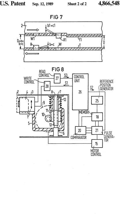
FIG. 7 is a corrected recording of tracks on a mag
netic tape; and
FIG. 8 is a block circuit diagram of an arrangement
for the implementation of the method.
DESCRIPTION OF THE PREFERRED
EMBODIMENTS
In the illustrations shown in FIGS. 3 and 4, a refer
ence track RT is recorded on a magnetic tape 2 by use
of the edge of the magnetic tape 2 as a reference straight line. First, as disclosed, for example, in U.S. Pat. No.
4,476,503, incorporated herein by reference, the edge of
the magnetic tape 2 is identi?ed, whereby the magnetichead 1 is moved perpendicular to the moving direction of the magnetic tape 2 until the write head W no longer contacts the magnetic tape. It is then moved in the
opposite direction while it is simultaneously receiving
write signals As long as the write head W does not come into contact with the magnetic tape 2, no signals are recorded thereon. The read head R, which in the
exemplary embodiment of FIG. 3 is fashioned as a
broad read head, likewise generates no read signals. As
soon, however, as the write head W comes to lie above
the magnetic tape 2 and a track T0 is recorded in in
creasing width, the read head R recognizes this track
TO and, dependent on a threshold, the edge of the
magnetic tape 2 is recognized given a corresponding
width of the track TO. Subsequently, the write head W is moved into a position by a distance DO by means of
a corresponding plurality of control signals to the elec
tric motor of the positioning means fashioned as a step
ping motor. This position is shown with broken lines in
FIG. 3, and the write head W records the reference track RT on the magnetic tape 2.
When, as shown in FIG. 4, the write head W is de signed broad and the read head R is designed narrow in order to be able to overwrite data, the read head R given a same width of the track TO, already recognizes
the edge of the magnetic tape 2 when, given an offset
between the two heads of b+c, the center of the write head W is not yet situated at the edge of the magnetic
tape 2. When the magnetic head 1 is then moved by the
same distance DO and the reference track RT is re
l0 15 20 25 35 40
corded, it is recorded in offset fashion on the magnetic .
tape 2 by the value b+c, referred to below as a ?rst correction value. The analogous case applies when the write head W is offset relative to the read head R in the other direction. In this case, the read head W is already situated on the magnetic tape 2 before the read head R
recognizes the track T0.
In the case of a broad write head W and narrow read head R, the ?rst correction value b+c must be taken
into consideration for the precise recording of the refer
ence track RT.
FIGS. 5 and 6 show the case wherein the center of
the reference track RT must be precisely located for reading the reference track RT, or for the recording of further tracks at prescribed distances from the reference track RT. This occurs, since, by use of the read head R,
the two edges of the reference track RT are identi?ed
and the mean value of the positional values at the edges
of the reference track RT is then formed in order to
identify the positional value of the center of the refer~ 50
55
60
65
4
ence track RT. This positional value deviates from the
positional value of the write head W during recording
of the reference track RT by the correction value b+c,
so that the correction value b+c can be identi?ed in a
simple way from the difference of the two positional values. It is not necessary to employ the reference track RT for the identi?cation of the correct value b+c.
Rather, this can occur after every recording of an arbi
trary track on the basis of the write head W when the
positional value of the write head W during recording is
stored and the center of the recorded track is subse quently identi?ed by means of the read head, and the positional value allocated to the center is compared to the positional value of the write head W when record ing the track. In the illustration of FIG. 5, we again
proceed on the basis of a narrow write head W and a
broad read head R.
When a broad write head W and a narrow read head R are employed and the center of the reference track RT is identi?ed in the same way as in FIG. 5, the write
head W comprises the distance DO minus 2 (b+c) from
the edge of the magnetic tape 2, whereas the read head R comprises the distance D minus (b+c) from the edge.
The correction value b+c can again be identi?ed from the difference of the positional values of the read head R and of the write head W.
Here, too, it is not necessary to employ the reference track RT for the identi?cation of the correction value b+c. Rather, any other track can be employed when
the positional value during writing by the write head W
and that of the read head R are compared to one an
other after identi?cation of the center of the track. It is also possible given both a narrow write head W
and a broad read head R as well as given a broad write head W and a narrow read head R to identify the varia
tion in the position of the magnetic tape 2 dependent on
the moving direction. For this purpose, the center of the
track is again identi?ed by the read head R after the
recording of a track by the write head W and after
storing of its positional value. Subsequently, the moving
direction of the magnetic tape 2 is reversed and the center of the track is again identi?ed by the read headR. The lateral shift dependent on the moving direction
is identi?ed as a second correction value from the dif
ference in the positional values allocated to the centers of the track.
Only one respective head system formed of a write head W and a read head R is required in a magnetic
head for the implementation of the method shown in FIGS. 3 through 6. When, however, a plurality of head systems are provided in the magnetic head 1, the ?rst
correction values b1+c1 allocated to the other head
systems can be identi?ed in a corresponding way.
It is also possible to identify the distance D+a with the assistance of this method, this distance indicating the
distance between the two head systems.
In the illustration in FIG. 7, two head systems are
present in accordance with FIGS. 1 and 2, these being
formed of the write head W and the read head R, or of the write head W1 and the read head R1. In order to now permit a precise recording of ?rst and second
tracks T and T1 on the magnetic tape 2 as well as an
exact playback, the correction values b+c or b1+c1
are ?rst identi?ed in accordance with the methods
shown in FIGS. 5 and 6. Subsequently, the moving
direction of the magnetic tape 2 can be reversed and the
second correction value can be identi?ed. This indicates
4,866,548
5
the moving direction. This can occur by use of one read
head R or of both read heads R and R1, whereby the identi?ed, second correction values may then be poten
tially averaged. For the identi?cation of a, the read
head R after its exact positional value at the center of the track T has been stored is subsequently moved to the center of the track T1’, and the value D+a+(b+c) derives from the difference of the two positional values. Since the rated distance D of the two head systems is
known and the correction values b+c is also known, a
can be identi?ed in a simple way and all three correc tion values can be taken into consideration when re
cording the track Tl, so that this is recorded exactly at
a distance D from the track T. In a corresponding way, the correction values can be taken into consideration
when reading the data.
The arrangement shown in FIG. 8 for the implemen
tation of the method shows a portion of a magnetic tape recorder which is designed as a cassette magnetic tape recorder. Such a cassette magnetic tape recorder may
be derived, for example, from German published appli
cation No. 32 44 165 or from German published applica tion No. 32 44 149. A drive arrangement (not shown)
for a magnetic tape 2 and a positioning means for the
magnetic head 1 are arranged in a housing 3 of the cassette magnetic tape recorder in order to position the
write heads W or W1 and the read heads R or R1 of the
magnetic head to differenttracks of the magnetic tape 2.
A magnetic tape cassette 4 shown with broken lines and having the magnetic tape 2 can be inserted into the
magnetic tape recorder. During operation of the mag
netic tape recorder, the magnetic head 1 engages into an opening of the cassette 2. The magnetic head 1 is se
cured to a head carrier 5 and is displaceable along an
axis 8 in a transverse direction of the magnetic tape 2,
together with this head carrier 5, by use of two bearings
6 and 7.
The displacement of the magnetic head 1 occurs by
use of an electric motor 9 which is preferably fashioned
as a stepping motor, but which can also be fashioned as a DC motor. A worm 10 is secured to the shaft of the motor 9, this worm 10 being in an interactive relation
ship with a worm wheel 11. In the region of the worm wheel 11, the shaft 8 has an outside thread 12 which is
in an interactive relationship with an inside thread of the worm wheel 11. When the worm 10 turns, the worm wheel 11 is driven, so that it moves in an axial direction
of the shaft 8. A compression spring 13 presses the head
carrier 5 against the worm wheel 11, so that this head
carrier 5 can follow the movement of the worm wheel
11 in the axial direction, and thus the magnetic head 1 is 15
20
35
45
50
positioned to various tracks of the magnetic tape 2. The ‘
head carrier 5 is prevented from turning together with
the rotation of the worm wheel 11 during the motion of the head carrier 5 in the axial direction of the shaft 8. During the insertion or removal of the cassette 4, the magnetic head 1 is pivotable in common with the head
carrier 5, but from the working position into its idle
position. The motor 9 receives control signals from a
motor control 15, these control signals, for example,
being fashioned as stepping pulses when the motor 9 is
a stepping motor. The motor control 15 is driven by a
pulse generator 21 which, when positioning a write/
read head in the magnetic head 1 to a speci?c track of
the magnetic tape 2, receives the control signals in order
to proceed from an actual position, for example the position of a speci?c track, to a rated position, for exam ple to another track. Such a positioning is universally
55
60
65
6
known and may be derived, for example, from U.S. Pat.
No. 4,313,141, incorporated herein by reference.
A speci?c track is communicated from a central con
trol unit of the magnetic tape recorder means or from a control unit 26 fashioned as a microcomputer. The ac
tual position in which the magnetic head 1 is respec
tively situated is stored in a memory 18 or can likewise
be stored in the microcomputer 26.
At the beginning of the operation of tee magnetic tape recorder, the magnetic head 1 is brought to a refer ence position which is identi?ed by a reference position
generator 25. For example, this reference position is an
outer edge of the magnetic tape 2 which is identi?ed by
a method as disclosed in German published application
No. 31 12 886. The reference position can also be a ?rst,
for example, outer or center track of the magnetic tape 2, or as disclosed in U.S. Pat. No. 4,313,141, incorpo rated herein by reference, can be a speci?c position of the positioning means which is recognized by means of a light barrier. This reference position is then the actual position and is stored in the memory 18. The microcom puter 26 contains an allocator which contains the posi
tional value of a track to be assumed. Both the rated
positional value output by the allocator as well as the
: actual position value output by the memory 18 are sup
plied to a comparator 20 which identi?es the distance
both with respect to amount as well as with respect to
direction from the difference between the rated and the
actual position values, and initiates the pulse generator
21 to output pulses for the stepping motor 9 to the motor control 15 until the rated positional value and the
actual positional value coincide. The magnetic head 1 is
then positioned to the desired track by use of the motor 9. At the same time, the pulses are supplied to the mem
ory 18, so that this contains the new actual position. For this purpose, the memory 18 can contain an adder
which subtracts the corresponding plurality of pulses
from the new actual position, or adds them theretO. It
can alSO be fashioned as a counter whose counter read
ing indicates the respective actual position and which is respectively incremented or deincremented by the
pulses output by the pulse generator 21.
As already mentioned, the motor 9 can also be de
signed as a DC motor. For exact positioning, a timing disc can be arranged on the shaft of the DC motor in
this case, a plurality of slots in this timing disc being
read by opto-electronic elements. In this case, the pulse
generator 21 emits signals to the motor control 15 until
a prescribed plurality of clock pulses has been read, this plurality corresponding to the difference between the rated and the actual position.
For the identi?cation of the ?rst correction value
b+c, the microcomputer 26 ?rst forwards the posi
tional value for recording a track (which is allocated to the write head W) to the comparator 20. The motor control 15 then continues to output pulses to the motor 9 until the ‘write head W is positioned to the correspond
ing track. Subsequently, the microcomputer 26 emits
control signals S1 to a write control 28, these control
signals F1 effecting the recording of signals onto the
magnetic tape 2 by means of the write head W. Subse
quently, the microcomputer 26 emits control signals S2
to the pulse generator 21 so that the generator 21 alter nately moves the magnetic head 1 toward the top and toward the bottom. ,Thus, the read head R is moved over the edges of the recorded track. A read control 27
thus receives read signals from the read head R and, by
4,866,548
7
nizes the positional values of the edges of the track and
identi?es the positional value of the center of the track. The ?rst correction value b+c results from the differ ence between this positional value and the positional
value allocated to the write head W.
For the identi?cation of the second correction value, the microcomputer 26 can output a signal to the drive
arrangement (not shown) of the magnetic tape 2. This
signal causes the reverse of the moving direction of the magnetic tape. It can repeat the same procedure in
order to ?nd the center of the track by means of the
read head R. The microcomputer 26 can identify the
lateral offset of the magnetic tape 2 dependent on the moving direction of the magnetic tape 2. It can identify
this from the difference between the two positional values.
For the identi?cation of the third correction value a which corresponds to the deviation of the distance of the two head systems, the microcomputer 26 emits a
control signal S4 to the pulse generator 21 after identi fying and storing the positional value of the center of
the track. This control signal S4 causes a positioning of the read head R to a track recorded by the write head W1 of the neighboring head system. The read head R
identi?es the center of this track and the third correc
tion value a is calculated from the difference between the positional values of the centers of both tracks and from the ?rst correction value.
The identi?cation of the correction values can be carried out when the magnetic tape recorder is manu factured, during maintenance, or can be automatically carried out by the microcomputer 26 from time to time. Dependent upon whether a broad or a narrow write head and whether a narrow or a broad read head are
employed, the correction values are subsequently taken into consideration in the positioning during normal operation of the magnetic tape recorder.
When recording the reference track RT, the correc tion is required only at the broad write head W. In this case, the correction value b+c is added to the distance D0 in order to record the reference track RT exactly on the magnetic tape 2.
When reading a track, the correction value b+c is to
be subtracted from the respective positional value allo=
cated to the write head W in order to exactly position
the read head R to the track.
As warranted, the respective second correction value
is also taken into consideration in a corresponding way. When recording the tracks T and T1 in accordance with FIG. 7, the third correction value a is taken into consideration, so that the distance between the tracks T and T1 amounts to precisely D. In addition, the ?rst
correction values b+c or b1 +c1 are likewise taken into
consideration here, and the second correction value may also be taken into consideration.
Although various minor changes and modi?cations might be proposed by those skilled in the art, it will be
understood that I wish to include within the claims of the patent warranted hereon all such changes and modi
?cations as reasonably come within my contribution to the art.
I claim as my invention:
1. A method for exact positioning of a magnetic head
to a desired track on a magnetic tape in a magnetic tape
recorder wherein the magnetic head is displaceable
back and forth perpendicularly with respect to a mov
ing direction of the magnetic tape, and wherein the
magnetic head has at least one write head and one read
(In 20 25 30 35 45 50 55 60 65
8
head spaced apart from said write head, comprising the steps of:
de?ning a reference position;
placing the magnetic head at a ?xed position on the tape and obtaining a ?rst positional value of the
magnetic head with respect to said reference posi tion and storing said ?rst positional value;
by use of the write head, recording signals on one
track on the moving magnetic tape while keeping the magnetic head at said ?xed position;
by use of the read head, identifying a center of said
one track by displacing the magnetic head perpen dicularly to a moving direction of the magnetic
tape as the magnetic tape is moving so as to sense
with the read head opposite side edges of said one track and then identifying the center of the track
between the said edges;
obtaining a second positional value of the magnetic
head with respect to said reference position when the read head is positioned at the center of said one
track;
identifying a ?rst correction value from a difference
between the ?rst and second positional values; and utilizing said ?rst correction value when positioning
the magnetic head to a desired track, said ?rst
correction value compensating for misalignment
between a center of the write head and a center of
the read head with respect to said tape moving
direction.
2. A method according to claim 1, wherein said refer ence position is an edge of the tape determined by mov
ing the head perpendicularly off of the tape and then
back onto the tape while recording a track with the write head and detecting the track appearance at the
edge of the tape with the read head.
3. A method according to claim 1 for identifying a
variation in position of the magnetic tape dependent on the moving direction of the tape, including the steps of:
reversing the moving direction of the magnetic tape
after determining said ?rst correction value;identifying a center of said one track by detecting the
opposite side edges of the track by use of the read
head;
with a magnetic head at the center of the track stor
ing a third positional value of the magnetic head
relative to said reference position; and
identifying a second correction value from a differ ence of the second and third positional values re
spectively allocated to the center of said one track moving in the initial direction and the center of said
one track moving in the reverse direction.
4. A method according to claim 1 wherein the mag netic head has a ?rst head system formed of the write head and of the read head, a second head system formed
of a further write head and of a further read head, and
wherein the ?rst and second head systems are arranged at a given distance from one another perpendicular to
the moving direction of the magnetic tape; and performing the steps of claim 1 for the ?rst head
system to obtain said ?rst correction value for the ?rst head system; and
repeating the steps of claim 1 for the second head
system to obtain a further ?rst correction value for
the second head system.
5. A system for exact positioning of a magnetic head
to a desired track on a magnetic tape in a magnetic tape
4,866,548
9
means for displacing the magnetic head back and forth perpendicularly with respect to a moving
direction of the magnetic tape, and said magnetic
head having at least one write head and one read
head spaced apart from said write head;
means for de?ning a reference position;
means for placing the magnetic head at a ?xed posi tion on the tape and obtaining a ?rst positional value of the magnetic head with respect to said
reference position, and means for storing said ?rst
positional value;
means for recording signals, with the write head on
one track on the moving magnetic tape while keep ing the magnetic head at said ?xed position;
10
means for identifying with the read head a center of 15
said one track by displacing the magnetic head
perpendicularly to a moving direction of the mag
netic tape as the magnetic tape is moving so as to
20
25
30
35
45
55
65
10
sense with the read head opposite side edges of said one track, and then identifying the center of the track between the said edges;
means for obtaining a second positional value of the
magnetic head with respect to said reference posi
tion when the read head is positioned at the center of said one track;
means for identifying a ?rst correction value from a
difference between the ?rst and second positional
values; and
means for utilizing said first correction value when positioning the magnetic head to a desired track, said ?rst correction value compensating for mis
alignment between a center of the write head and a
center of the read head with respect to said tape