The Ultimate Compressive Strength of'
Thin Sheet Metal Panels
Thesis by E.. E. Sech1er
In parti&l Fulfillment of the Requirements tor the Degree of
Doctor of Philosophy, CalifQ?'nia Institute of Technology~ Pasadena, California
on
:!?:art III ... ..-Flat Sheet .Panels Beyond t.'he 8ta.bilit.y
Approximate Theory fl'
-:Wirst
Par~ IV--•E.x.perimer1tal lt.pperatus ar:d Eesul·~s of First
r;x-Pa:rt VIJ: ... Application to C~.rrved; Sheet
VJ a
on
References
repor~
of
o~ot
thin ehe~t metal panels a the gei1eral formulas for theequations hs:ve been obtained
bytb,eoreti
total load
UDsti:tfened 11 simply supported panel can be g.i~ven by
P=
c
JEc:rt,_
and ~ha't the c~nstant. C ill
b7
of
ted load&
lous
C
af
{A )
~
)
~
.{:
(II
t )
fr
~)
E • the Young's medulus of
t •
of
b
=
o:r
R llf rs41 us o'£
P~'"'"'''-:!·-~ tt bo tb
round to
:failure
ot
The author Wishee to his appreeiation of
the assistance !'urnlshed by members of the st.aff' of ·t.ne
Guggenheim Gre:dnate School of' Aeronautries at t.ne Calif'ornia
of Technology and also of'
by the
In parti eul
ar
hec.
:B., llil1ika.n, and Donnell for their helpt'ul suggeetirinuiand criticiem&., Also itr. Raymond 0£ the Douglas Aircraft
co .. " who aid.ea by suggestions makir1g the work more a.ppli ...
cable to deaign~
G:rati tude is also
Institute
or
Technology, and in particuJ,a:r to ProfessorNewell of that institutioD for giving access to their ex~
perimental and Qa•i.~ ..
Of the stu4enta aiding in weri:: ~ partieUlar
:mention due to ][essrs. Hutc1'J.ne 11
and Childers~ for their .,
The subject. of t.he stability thin pla:tes
:fi rat became of' praeti onl im.por tmu;,e in the :fi el de o:f
:naval architecture civil engineering. In
archi-tecture,. the designer was interested in failure of
side plates of a ship they were to
and shearing forces in the
ceuJe, "the problem watt l.ae:o eompli.catet!
In this
par ta of the by the additi co:! o:f t-he water pressure
acting normal to the plane of the plat~.. l engin..,
eer f"aeed a simi lsr pr()>blem when d~si gn:».ng l~~:rg.e plate
girders in which other dimensions o.:t t.he were very la.rge
in compari e:on to thickness of m;:lter1 used.. These
bea."Ils were .subjected to loads whi el1 ten.si on,. compres..,.
sion" and shear loads which in the pl.ane o:f the web" and it 1111"1!.~.s the deiii
tha. t buckl i of
¢ ~ pl'obl em ·to t::to eonstruct his beam
did
In both e>:f the above lure timS eo:nsi. clered
to have occurred when the plate suffered any appreciable
def'ormati 011 in a direettcn perpeudieulaI: to i.ts plane; since
any loading above this 'lllcri ti cal l.oatP' cauaed a, rapid. in-crease in the ae:for.wati 011 in a direct.i o:n parallel to the
plane of the sheet., This large defol"lnation, if accumulated ewer a large structure such as a ship or bridge t would
cause total displacements which eollld net be tolerated ir1
the desing of such a structure.,
Whe!l :flat and curved sheet; vms first used i'.'.l
aircraft construction. the tendency \"las to design the sheets
on the same basis as tbat used. previously.e i~e.,, on the
basie of the stability limit et:r the critical. buckliug load., 'fhi s 'buckl.ing load, however wae ''ITer,y low :fo:,r t.h.e ·thin
ma·t;.-erials that were used in aircraft construetiou and this
cri ti load induced stresses in al eh were
:far belaw ·the stresses that would cause tion in the sheet,.
It was also noticed that if
p&p.els were lQaded above the stabili
thin sheet metal
they continued
to carry a certain a."llount of increased losd
m
thout sufferingany perBuan~nt deformation., Consequently there arose the
second problem~ that ot: daetermiuing the ma:ximwn permi as:i bl e
load be:f ore the sheet suff'ered a perxna:uent de:fcrmationt or
bef Q"re the stresses reached the
is.l at any point.
e limit of the
mater-struetur·es,. such conditions as i.ndi above are quite
permissible., The normal flying or l.a:m:'ii.:ug loads ot1 an air0
plane are tisua.lly quite eompar loads ch ~Y
be applied under extreme conditious ods o:f
time.. Consequently it may be possible to design t.he strEtssed sheet. of such a structure so that i t is in the unbuckled
st~te for !lo-rm.al lead conditions and Cfin eerry considerable
ls.trger lo~ds :in the buckle-de s:t.~.te wne:;1 sub,j~'eted to extreme
eondi ticmsi;; In other ,, the
be based en t.he ultimate lead car1~yif1g
load should
caJpac:1ty of the
sheet rat.her tha..?J upon the load at \'iit'..ich. the $heet re.lches the sta.bi li ty limit ..
The det.ermi.uat.ion e:f the e)~af!.1'i c l.i ty limit of flat sheet members .has cally aud
theoretical. was by
:bis method. or ot.he:r methods giving
other~).
one
m.ethodis given i:n II oi' this paper."
:1) and
r~Eu~r1 ts, are
!he treatment ~f e beyond
r,Jta,bilit;y limit is quit.e renent~ lt been o1rliained, ex""
periJ&entalJ.y a nurrtber at times but was first .eon&idex"ld
seriously in a publication· of Newell~s (Re:fe:rence 6) and i:u IL.A • C.,A,, Report llo. 356 (Re:f'ereuce 7) on l'irOrk done at
These no tempt
ga.v e the experimental data the hope that these results
would be a guide ~o
on s 001 "1frl!iS
m~.de by von aud it is this and its .ez; ...
pc.nsion >dlieh f orma the b~eic pnrt of this p~.pe:r.., A semi-the:ore ti cal
edge ·compression it! the: :rJ.ane of ·the sheet, aud this theory
has been checked by a large nt!!nber of GXp~riir.ents,, Tr.ii s
has t.hen beG"n
m
th and. witbeut stiff en.ers*' thepersonally by tb e o:f it
and part of it uas performed at c .. I,. T ~ by gradtu~,te stude11ts
in Aeronautics.., 1.£"ention of authors ru~d publictd.ione wtll
be made as their work is discussed.:1
II. The Stability Limit
atabi li ty l:bd.
'the method is
quite general ,
on othe1·
and to
x
s
stress o-
dis=-Y •
ot'
y ii:· b., See Fig$ l,.. All edges of
to
simply supported"' • if the
is
the general dirreren•~lal equation
(l)
mld, since er\\ -= 7""°"J:. o cr1 -:::.. -er
t
1.E
J'l-r6 tJ. i! =er
-n_(,~"L) .J'1'\.
(2)
which gives the differential ecruation for this particular
(3)
the ca.se of simply suppor·ted edges" can
be given by an equation of the !orm.:
where
and are integers,. EqtW.tiO!l {4}es the tlons
;l:.-:O
,
~ a.. f- 'Jl=-01 c._J kl,.::;;: 0
put ti the values
into equ:ation (3) we get, after dividing through by
the on
t'E
f
C':)\
In"(~~:)~
(:rr-rJ-
er(
¥)~=-o
i"Z.(l-;...").) ~
(5)
wllich ean be solved for er , yi ding
l.
+'2..
l
J?.
.)l.
r '(
Vi)~
l
~)"t.11..
0-=:. ll.b-,.;-•·-'·) ~
{.!
G.... bJ
(6}
{ '1)
(8)
.A plot of' K agah1st the b/a ratio is given in
Fig., 2~ Thi a family of curves indi that the critical.
the sheet has a length
this i a the eune of -,, a.iUl1 . . ns t t:.ne ., . . bl ~
for
b/a.
that1 l.$10 it
suffi eiently is
accu:::rat e to oonsi.der thgt
Thie method
buckli
to give r1cHial liwe&
o ...
~--~--1~~..,.._~_..~~..1,,,..~...J..~~..i...~-'-o I
very a~.tisfacto:ry for plates Qf the th:tckn;Jse used in naval
and. civil engineering as it. was poseil•l.e to otit&.in stresses reasc;mahle close to the ela.etic liri:ii t of t-be material t':ith
steel-
!n
thick could be used up to 30~ w.i.de and of any length thout having the buekling stress tl1e elaatielimit (30,000 lbs
stress falls of£ proportional ·to the of the thickness
'E"f:S appli
design of aircraft of
materi 120
to a
a compressive get the buckli :ug stresei "Lrp
for any b/a ratio equal to, or greater thau l~O,. This ob""
vi ously means that :m.:unerou.;; stif:fene:rs must be used hJ order
to break up the sheet into a large nU!nber of very narrow
panels., This leads to an difficult
construe-ti on whi cb would not be used merely :rrom an eeonom:l c:
staua-If a panel of the same material h1 made 4* wide,
the buckling stress falls off to
ch is too low for ecorrnmi
cm this pauel is increased after buckl
average stress nf t.1vc1"" 7" can rea.ched
this last streee is still far belc;;: the cla.sti,.c limit o'f the material,, the increase is· impert.ant enough ·to be giv£n serious cousiderati.011 for thit1 sheet :met.el pDnels... Part III will consider thi .s increase in allor,;:;;b.Le stres$ ~boV~! the
&t.;;.bili ty li:a1i t i i i detail"*
III,,. Sheet Stability
pression
(Re:ferenoes 6
and etrikingobtained gave
buckli;ug
nearly
independent of the width of the
:::=s:
...
l/~.
it- . '../I
((l)
load ~ra-s
carrie~ by that part o~ the
was the
(C) the buckled state" In other
the
ila:r to the dth design
I
w
t-b
:first of
assumes th~t in th:J,s regi.on the plate
are
8}
of the she~t
by VOil
ene
-tl.E
'1..l l?L l..)
and eqi11a1~1 on
or
er:::
To
This gives~
:from wb.i
it
1tl.E+71...
l~
\1 .. ( '?~.<l,,."11..)
J..r
find
--'-
4w"L -..1
JP-=
o
J!
~ l.w1T l. E 't-a. ~i1t.·c.a. l :::- \1..(l-j4-\)W11..
solving tbi s !'or effective
(9)
and the total load c-1:1rried by the sheet; 1 ftq'.:ia,l to
(
(9)
(3)
(ll)
{12)
'PToT-=
2.wto"-:::
~n.~:_.,.>
JEcr -t1..
(l.3)
- r
JE
_j,,.l.... - "--.f 'j a-~ ~I!.f'om:"tl1 side :free (Fi.g" 4c)~ mis
ried out by Doiinell (Re:ferem:ie S) and
total 1oad of the same
nell's equation is "D ,
\ lr?J\~':it
:ro11owea. since they
def
om-(
)
with
t.he-an equation
as (15) 0 Don•
(16)
the
as a function of the ela.st-ic propert1es of the material" the
sqttare of the
of
the lo&d was i.nde:penrlent o:f the Width of the
sidering the value .of
r
for normal {metal)to he equal to o.3$1 equations (15) and {16) give us
tp-a"->t
=
'LG Ii
Ecr1
t
"t.' . . r.:::"".:"
t
l...1>
-.:;.~.::
\.1. Ii v E<r'1
!mental values
0
r:1 Sr. I R.o~
Molil i.,;
mental values of Cr~ ealcula:ted f'r@m
foutHi in Ref'erenoe 1 are shown plotted
$eeE. that nearly elcl (a~%) of the
Gf do lie within the range
order to more
cat.et! by
au exper-imental program ?nu; started
of iree:hnol ogy in the Glagges.meim
was felt faults
,fO(J
1, and it iB
val u.es !tn.,'
California lnst1 tute
a~ mt1ch e.a po~s;t bl., e in the tei::;tf ng !1.,.T*T.
(l?)
IV"' nperimental Appa.ra.tus of First
Experimental Tests,,
The testing machine is
F1G. G.
in Figs. B and 9, and Fig., 10 snows .~ photograpl'l of the ma.chine
in use,.
me
upper head of the t.e.st:ing machine cons.ists of a1 ten inch I-heam fastened to two.
upright ten i:uch channels11 ami
the lower~ moving head ot" the machine is a simiJ,ar ten ineh
I-beam pivoted, on ball bearings.
with a a.rm o:f eeven feet.,
which might introduced from
and lower beams were usetl in
]'.1g,. 10
order to eldn1.nate any deflection o:f the testing heads under
load distribution over
the edges o:f the specimen.,, The ho:rizont.al motio11 of the
lower beamf' be:tug approximately 0.-01 inch for every inch of vertical motion, eo11ld be neglectedg foe the vertical
motions obtained in the experiments wer~ in general less
than a o:r an inch ..
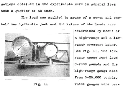
load was appl;t ed by meaJl~ o:r a seven and one•
half' t.on hydrauJ.ic Jack a.ml tbe valu.e~ gJ: the J.gutl.:s were
Fig. l l
by meaus of
and a
low-range pressure gauge"
Fig., ll"' The
low-range gauge read :\'.'rom
:0-2000 pounds aud the
gauge
were
per-iod1cally cal.1brat.e<1 against. a standard 'type t.es;t:i:ng m.achJne.,
fbe surf'aees of the I-beams next to the specimens
were faced th a strip of
heavy cold-rolled steel
having a 1200 V0 groove
:t'\lmli:ng lengthwise the
center of the beam<!" rbese
twtl V-grooves could be ac•
curately al iSJ1ed ll' one above
the other., by means of
ad-_Justment$ on the testing 12
machine~ The sides of the spec.imens were al so supported i:n V•grooves, in thfs 'case 30°11' which could be adjusted for any
wit\ th of' sheet d~aired and Vihi ch could so
that they were of
A photograph o;f the edge s11pports first "sed 1 s 3.hown in
manner I!
lower. edges acting i:n the plane of the
'first series
which were all 12fll long and which
sheet, al:ominum, and brass. th a
O~Ol2 to 0"067 inchtHl., Since the Ka.rma:in (Part lll)
ii1dicated that the total load
material~ a wide range
or
to check the equation!!' even though som,e of the materials
st.:ructura.1 materials.., It; wa.s also expected 1~hat :for very
large and of' the o this
1n order ~o establish limits of
the material was ordered crated and shipped flat
When purchased and was ueed as reeei ved t :l:"ej ecting however•
any specimens whiqh showed ci1nature or
:f ects.,, The ends were sheared iH.J.uare and loaded edges of
the specimens were made -cinular as there was a te1uieucy
for !lat. edges to ride on o:ue si.de of the upper and iower
on tl1e
cattsing i t to fa:Ll prematurely" A number -Of scattered ene inch wide specirnens were taken eloee to the l.arger compressio11
specimens and inese were used as
determination of
Tb e el asti. o p:roperti es were
deter-ing mea.StU"ed with balanced HU:ggen.,,. berge);" tensiomete:rs.. See Fig,, 13.,
The compression tests
were run ·on each specimen and the
value of the ultimate load iu
compression was tabulated,, From
th1sac using equatio11 (15) .. the
value ef Cf could be determined§ since E aud
~
were given by thestre.ss-strain curve of
:ror the detern1inat.ion of the
definition of
considered :suitable to check
first set of e.xperimentt?.J. tests,.
It
'Eor the
Fig,. 13 be
of was
this time it ~J:l
that the
a further
analysis in o:rder to determi1ne whether or not this d.iffereuce
was due to experimental inaccuracies or wlJ.et.ber C4\' ;J. was some
function of' t.he experimental variables"' Consequently a closer
investigation of the probable stress distribution was earri.ed
out and s second approximation to the prob£d::ile ultimate load
carri
Second Approximate Theory
The first assumption made in determining the
ul-timate load that could be earried by a thit1 sheet pm1el in
compression was that the center of the sheet carried ~10 load
t.he edge regions supported the load
by the sheet.. However 1t an investigati.~n of' the action o! a
sheet during .loading shows that this ass:umpt.ior1 needs to be
mod.if'ied in order to.more closely approach the actual load
At first, the sheet remains in its original pla.ne
form ~s the load is applied. At a eertain load., the. critical
buckling load .. which ea11 be determined by the equations
rived in Part I!9' the sh-eet buckles in a which is
is continued" the e.Qges remain restrained and eontin:ue to
being in the buckled state,,. c~:n carry little or no increase
in load. however they still carry the stress corresponding to
the critical buckling .load on the panel., The second
approx-imation to the ultimate compressive load is Ga.sea on t.b.e above
assumption8 i.,e. that the center p.ortion of the sheet carries
a stress e:orrespot:uiing to the critical buckling stress o:r the
given panel and that the edges of the sheet carry a stress
o-
distributed over the effective widthConsider a tz:11in sheet panel of length I., width b,
and thickness
t.
made o:f material with a Young's modulus E, e>.: ~., .. ~Pi..
,.,
v BQnpol' ;;:- f,~Q on a.ll i'ow~and subjected to ~ eompressiou load on the .upper aud l.Oll'<·er
ons over et:f'eetive on each side
uniformly distributed stress
i
w ~ I
1-- I w
er
a11d the center portion of thesheet~ of width (b • 2w), afll"ries
the critical buckling st.ri$as
b the sheet,
Ob •
Ua1ngKa,rman assun1ptionv equation (12}
as
(12}
and the buckliug formulair equr:rtion (?) gives ll-i.. E+t...
0: ... k
-b IZ(I -.,µ.'!!.) b
"-(7)
(l, 7)
(l2a)
(7a)
depending upi:m the L/b ratio given
Tbe total l ends is given by:
aud the total load carried by the center f!ac·t1on 1s :
,
1'~(b-lw)tcrb= ~l.:aEt}(\- ~
1\~~)
(.19)By adding the two. ve get the total load by the
combinatio11 as::
'° -
P-t
'P~ ~ecr
t\
~;r
[1..,.
~
[±..,.
~Et.?.
l
l°'Tn - - "Z.ot
VU
b oC2 0- b'l.-_jLetting
b:Y sueh a
l -
Ir
t
ii - ~~ b
val·tte ( 20a) we
"O _ ~
+l.
:z.ifr.
~ .\!\ _ ~t ",,_] -=r
JEO:"
t'l.r ~" -
"£11",
,...
~r.
+ l« ") al.?. .fl~ ._,.. ~in which
{21)
(20a)
(22)
tnis
(20b)
vl.i"t.h the value
o.so
and theu leaves 6f as a f.unotiou ofthe L/b o is greater u:ui ty
and that. i t is conservative to U:f.le this value for K f'o:r al.l
values of L/n,,. Taking theu" 0 eh
give.s a •slue o:f« a 3.,29, we set for cf~
cf
=[1.£11
-t3."r
i- "·
G
'°A
j
c2•>
hol,d up to when the two e1feetive widtha would
Join, or when (b - 2w) s 0.., From this point on, the failure
would be purely a yield point fe,ilure and the total load carried wottl.d be equal, to
'f'::.
b
t<r :::CJ.'
-V E<Tf''"
(25)place,.
of
and~ putting it into the ~c:rm
we f'or
C ''-
k: 1r1.fE
t. -
K
Ti~ ~-=-
3,,
1.). (27).f -
olt.{~
b - cl:for the region i11 whieh :K :r: 4.,.0 an<:1 OC.
=
3"'29., This gives a straight line as shoml in Curve III in Fig,. 15. '?heclii"'-after buckling takes place.
In a recent paper
byCox of England (Refere:uce 9)
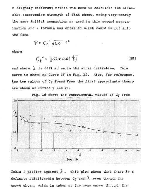
e, ~lightly d.if:f erent method 7nii user.'l tc calculate the allow=
able compressive strength. of' :flat sh~etll' using very nearly the sa!l'ie .iui tial assumption as used in this seeend a,:pprox-i1mat1 on and a formula watil obt.a.ined which CQUld be ptit i11to the f'orm
where
and where
l
is defined as in the above derivation,; This curve is show--.a as Curve IV in Fig_. J.5.,, Also, for :referenceiithe two values of
Cr
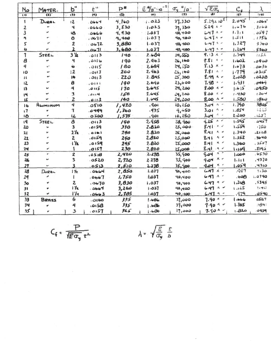
:foUlid from the first approximate theoxyFig,., 16 shows the exper:bneatal value-a ot' Cf' :frmri
F't.G. lb
Table I plotted agaiust
A
4 Th1 s r.lot ehOl'!S- that there is adefini~e rela.tionahip between
Cr
anttA
even though thech i& .taken a~ the :mean curve through the
plotted poiut.sll' does not agree with any of the theoretical
Tnis first set of
truat could be au.;pported by a flat panel could be given by
the equation
and. S'eeond p tha-t the e~f:fieiant
Cf
wa.e a functionor
th(~parameter
for a wide range o:f materials 11rlth different elastic proper•
tigated. the affect of' the length of the specimen on the
deter.minati o?l of the exact shape of' the C:r vs ..
l
curve wasmade on flat sh~et panels., Wlith the fact established that
the value
or
Cf eould be plotted as a. :funct,ion ofl
> a, muchlarger series of panels were designed in order to better
determine this d~penda:nce.
In order to obtain a number of points over the
whole range of' possible values of
1
a 11.:u:aries of specimenswere choseu O., 064" az:ui 0"' OS21t l 7ST Dural
0 am!t Oji\ th wi
:from
l
thatthe value of Cf w~..s more doubtful £or am.all values of
A
theccncu:!ntre"tion o:f e~perimeutal points v-ras made greater as
A
decreased. This lead t.o speeimens ranging from 0,,8f'For the dete:rmi.:tia ti on
or
the dependence of Cf onthe length of' the panel, seve:u differeut lengths o:r sjflecimens
to tt in This gave
from 3 to 21 inches
those used in the first group
being
of thix1
to
leaves of these blocks was negli.gible compared to the
The experimental resulta of these tests are given
i:n Table Il plotted in. enn be seen from
.l.O that there ii;, no
c:r
L/b ratiosC'f ·a& L/b decreases as show by the dotted curves~ This is
as would he expected as tl'le stress carried by the center
:r·egions of the panel i:nereases as the L/b ratio decreaaes
from 1.0.., lfowever !t for design purposes'!' it is :felt that the
iu;ie of the soliG. curve in Pig,. 18 :for all values or J,.,""b will
In fable II the valtie of was tak.en as the,t point
on the curve of the material
eorre5pc:n-ded to a 0,,.2% el onga ti on o:f the ., Thi$
was donejc :first. to agree with the d:e~ini ti on of the yield
point given in the design :requirementst and second
because use of this value seemingly gave less &eat ter
to the experimental point$. fhis scatter V;ms particularly
noticeable in materials with a .stress-strain curve !!hieh
departed slowly :from a straight linef failure seemingly bei:ng
retarded until a st:rl!s.s had been reaehed which was
consider-ably beyond the proportional limit of the material,. A
s-euasion of the sfil.a,pa of the
of
the equations fer flat sheet~ equat.ions {l6} (21)., This
0
L-~~...;._~~-l..~~~'--~~-'--~~--L.:-~~~~~~'.'""-~~-:-~~~~~~~-0 .1 .z .3 ·"' .s It .e. ., .a .9 1.0
't6
was particularly :fortunate since the whole theoretical
dis-cussi on has been based on ~he assumpt.i ou that the small f!,e ...
fleetio:n theories hold beyond the stabili.ty limit.II' This
assum.ptio11 has made in the derivation of all of the curves i:u Fig. 15,. Obviously, after the sheet has gone i:nto
flections in w~ich the stresseB
introduced.
eonai d.ered as as tl:i.e stresses
due to direct load111 This: treat ...
but as yet is not in a form t;hat
F1'1.
17
ca-n:fi:rmation o:f'
J;n investigation o:r the exr-erimeutsl curve crf F,ig,,. lS
it is the theor~ticel curves o.:f 16
:for nearly all valu~s of
l .
the loading over the ef'feetive width cannot be trn:i ?orm
as
the stress mu.st be a ma~x.i.mlillm ·~hein Fi
would
tion... The position of' the experimental curve shows this t.o be correct exeept ?ery small Tal ue.e of ) ....
:r·he increase in the value o:f Cf at sm&J..J. val~ ues oi·
"lralues of
l
huUcatethat either t must be If b
the
value of the stress carried by the center.portion of the sheet
proportionally,,, there is a tendency
to increase
for decreasingvalues of L/b is shown
bythe
dotted curves
th.at !'or de-flign purposee i t is· felt that the use of t"'le solid
curve"' neglecting the of L/b j,s advisable""
There is another e:r:reet, bowever,f which WE!S first
natieed when testing de specimens of' thin brass., Ot"ling
easily noticed and the bnelcli.ng action was_ visible thrtru&hout the loading_.. 'fak:h1g,. fo.r e~ a sheet 12" long" 14" .wid$ ~
and 0,,016* thick!>· corresponding to a value of ).
=-
0,,025l> the·buckling f'iret started at a very 1-ow load and was iu the !orm
of one halt-wave~ as would be expected from the buckling
equation~
i:mately
the edges
Thi!:! conti.nued tL'tltil a load. erqual to appl"Olt=
of the ~ailure was and then
t,he sheet bu.ekled in of five
o·istt tb.e center 01.'
finally a number of small ~7a:Ves (
Fig., shows clea.rly the mult:lple wave fg_rm whieh thin.a
wi.de sheets go int.o,.. This ple wave eat! also
:oot.!eed in ·a, cf the Scpecimens shOtnl in
Fig<!' 19~
The :e.bove action was observed :f o.r all. of the
panels tested l?.nd the e:ffeet seemed to decrease 8.S the sh:eet~1
becanle narrowerq This wattl.d seem ~o 11.Hiieate toot the
wider sheets the distribution o.f et.:ress on the lottdec! edges
could not be accurately eXJ:iressed ev·t;m by ·the iaeeoru'1 met,hod
waves probably gives a sti, f:feulng ef':feet which is shown by i:u.,.
crea~e 111 the value e:f a.s the V<::-~lue of }( decreases.,. A
more caref'ul investigation
ot
the actual wave torn .of thesheet . under load is being plam1ed in order to se-e i. f it will
not give a better ide~ as to the aetual stress distribution
acro;;;;s the loaded edges~
Fig.. 19 shows a number of photograp11.s of test
panels taken after :failnre-t i'""n which the type of' wave
ean clearly seen., Al so$' more rigid edge aupporta for
the edge$ of the sheet C.?..:ll be seen ill these
r
'
l
't
[-,·r r
<I
r-),1:1
,J
-"" ___ _!
i
!
_I
VlI., on to Pa:nels
method of Part V"' wil~l ntiw be expanded to cover
a simply
R
\
T
.load in t.he planea- -0f the sheet and
parallel to the
s the
cylin-dri
l.
l
tnodu1 us of theand the yield
l>oi:ut to be <r~ ... Since the Si•"ies of the sheet are simply
supported~ they will undergo a stress condition sim:i.l.ar to
that found for the
at the very edge
at. sheet,. i~elll' at :failure the stres:ia
be
a;
al~.di if.hi"' atreco wil.l. decreaseas the center of the sheet approached~ However~ for
eimpl.if'ica.tiou, it will be asa~ed that the region very close
to the edge will act as a flat sneet a:ud will strpport a
stress <.r over an effective dth
~rom the e-quation for flat sheet1
(29)
(30}
,. Appendix B.
total load carried by the tuo aide regions
wil.1 then be
"P-==-
z
w+cr-=
L+
Je:.(J"'
t~
(31)specimens could be cl.osely approxin1at.ed by the
r;:-- - A,,!'>. 1'-
.::t
{
32 }UC. - u•;JJ.._ R
an<l a recent paper by Redsl:uaw i:u (Reference ll) J:ias theoretically that 5a.in€ critical buckling
as :for a complete eireru.lar cylinder., value oi the
cie.nt in eqtw.tion (32) also agrees with the
ax:i:.erimental d.ata gi:ven in an N .. A,,,C"'A .. Report by Lundquis·t
(Ref~renee 12) ..
'llllill U'1t Ci;.I'ry onal loe..d
·t.he the
aides whicn will enabl~ the side regions to tiomu
stress stbove t.he critical stress V&;lue for the center regiottS9
as-that the st:rez.s distribution over v simply suppor·~ed
curved sheet panel is as f'ollo1fie:
a)OVer e region o! dth ¢Cw~ en each siclel> there is aeting a.
a- .,,
b}OVer the cent!'al region of" i1r:i.dth (b - h) t,here j,s
by Fig<:r 20.,
load carried by the side regions is given by
e01t:ta1;1ou (Sl} the J.oad cal"ried by the
Pc-=
{b-lw}cr-"'t: bo-c.+- 2.wcrc.t{33)
( )
which!' if put into the :rorm used in fla.t sheet caleu:lati ons • becomes
(35)
where
(36)
which can he put irito the form
where
1=
~+
<5 I?uo the equ.i:;ttion eau be ll\!Titteu aa a t·u:uetio:i:i of
A
a:ne1
alone,as given below
e-_ E
+
+-~
bJia..
c: - -
er
-= - -
$ - -=AV\
R b 6 R. ·a- \ (38)
(39}
o.f' C plotted V) is given in Figia
plate~ "\ t £.. ~ O,. a1ui C •
Cf:'"
which gives ths tI·l.lee.x:-µ~~r:i1J;riii,:111;:~J..val.ue for the :flat plate; since iu equation (39) and Fig .. B-2
Cf i.s taken from the value o:f Cf as a :n.metion ef'
A
as de.,,.te:rrnined e~perimentally., Thua11 in Fi :B-2 , the curve f 01'
1
=
tJ (!!orresponds to sl"leet.s wi t11 in:fini t.e radius er flat sheet specimens.curves for the value of C are so limited
by their intersection with the o.urve giving the yield point
aud point& to the right. of thio curve ind.ioate that th'9
stress in the center of the sheet ail- by (32)
is higher than the yield point stress cf t.he material aud
t:.t.w.t the pa.nel would f:.dl as a yield point failµre at a value
and Gale ou the streugth of' cu:L"V&d
sheet panels series of
in
C :from the experimental value of the total load by the equation
(
~
'Pfitf (40)VEa-.,
t'l.1n liihi ch 1 t has been assumed that E • 107 a.nd o-~ • 36, 000 lbs./sq.in11 The resul·ta1 of this calculation are give:u in Table III.,
~rom 'fable JII it. c~n be seen tha.t the above method
o~ calculation gives a very good check on the values of the
curved sheet constant as determii1ed by experiment"' and could:
be used ttireetly .for the calculation of the maximum compresei.on
load that could be resisted by a curved sheet panel withou.t
sti:f:feners.. IIowever 11 a cl.oser inspection of' the e.xperimental
a.nd theoretical values seems t() indicate th.at there is a
consistent varia.t.ion of the value of C with the length of
the speci.me11, the shorter speeime11s g1vit1g higher, and longer
specimens giving lower!!' va1ues than are obtained by equation
(39)~ Taking the average ratio between the theoretical value
of C and that obtained by experiment for each length, we
obtain
iation
For L
=
6"
C(exp) • lit.l C(t.heory)C(exp) •
i.o
C(theory)
C(exp) ~ 099 C(theory}
There are two possible explru1ations o:f this
var-th length .. the first being that the stress<»c. is a
'function of the length of the specimen .. &i,nce the last aeries
ot:
tests 011 flat sheet pro-ved t.hat there was 110 varia~iouof importance irt Cf with variations in length. This source
of error., howeve:rt does not seem importaut as the value of
.::Tc. has been checked for a large range of leugths of specimens
The second possibil.i ty
ot:
error lies in the method of edge support used for the paneis4 The ai del:l of the aheet. were supported in V-grooves with in1 angle of 45° which istoo large. These grooves initially hold the sheet in a
straight line, but if any buckling takes place in the center
of the sheete the edges are free to move out of the grooves~
This motion will allow the edge of the sheet to deflect
perpem:Ucular 'to the plane et' tb.e plate aml to a.et as an
Euler co1mn with a restricted range of' buckling,. Thi;;; would teud to decre.as.e the load carried by the edge region and this
bu.ck.ling load wou1d very likely be a function of the length
of the coltmu:i. An investigation of the sti:f:fened sheet
panels,, ct.1sctu:H:u;~d lat.er~ seems to 1ud1 cate that t.he &econd
source of error is the most probableo
On the ba&is of the above discussion, i:u1d on the results of check with stiffei1ed. curved _sheet panelsie it is felt. that the value of C obtained from equation (39) or
Tl.II~ Sheet Panels th Stiffeners ..
Sheet pane.ls are :never useii in the construction
of an airplane simply supported as those o:f the experime11tal.
tests we have just been discussing, but always have
stif-:fener shapes forming the bocu11da.ries of the panel. a.re
psrt.1 cularly interested tllen in the load that
can be carried by a thin sheet panel to which are attached
~tif'feners rtmni11g in t.he direction of t.lle applied eompressio:r1
for this determination a method suggested by
Lut.u1qu1st (Ke:rere.uee 14) .ts it:~ed¢r The e!'recti ve widtll 0£ tbe sheet is to act with the stiffener section as
l l fail u:nder ,a,
certain eh will a ftmcti on of
the type
ot
sti;ffener~ the e:ffecti·ve width o:f the sbeet.the eoltUn.- For the determination of the effective widt.h11.
tha equation for f'lat sheets is used
w~
C+If
T2.
ye;-Cf i.s a function of ).. where
l~ ~t:
It can readily be seen that. the determination of the true
ations. fhis calculation is earried
out
in detail iu Appen ...dix A and consists in starting with some arbitrary value of
cr;t-
e.g. the value of. the :failing stress of the stiffener with nQ sheet attached, calculatiu.g the effective si d:thcombined sheet and etif:fene;r section, and trom. this obtaini:ng
a. second value of
oSt ..
This procedure 1a .carried out un1~ilerst and a.re ecmpa:tible, which usually invol-res not more
than three approximations., Then, the total. load carried by
a sti£fened .sheet panel (fl.at) is g:iVEm by the sum of the carried by these sheet•pl ua"!'stifi"ener eolt.mltlt1:L. This
gives
where .a1 1a the area o"f the st:iffetier, ~ ii' -the area of
the sheet attached to the stiffener'" and
u;.
7 is the final(41)
In sheet panels th s.tif'feners,
the pan.els carry;, i:n a.ddi tion. tc the above load carried by
pai-t of the sheet lltlxt to the · ati f':f eners, a, load in the
center of the panel given by the equation
~
I :.
~-(
b-2.W)
t
(
42)load that can be carried by a stif:fened curved sheet.
is given by the equation
~cT~
Ltr;t(
~,-t ll~)
-tI_(b-2.w)t
(43}where the first term indicates ·the contribution o.f the edges
of the sheet with the attached sti ff.e:ner sections and the
seeoud tei'm indicates the co:ut.ribution of the ce11ter portion
of the sheet, or the part due to the curvature of the panel ..
The calcula,tit>u of' the predicted load ou the basis
of equations (41) and {43) bas been made f.or a number of
sheet and stiffener combinations tested at I .. 11\, and the
results are given in 'fables IV s..ud Vo ~able IV gives the
ca,lculatione for flat panels and Table V gives the ealenlated loads for curved panels.
In Table V i~ will noticed
two values are given for the predicted l.oad,. These are di&•
.cussed detail Appendix A it is Cfn1y t10<
mention l1ere that the speoimene giving these valties lie
out-side of the U'5ual range 0£ monocoque deeign,
inas-much as they have a very small radit.is ~f curvature coupled
with a. large sheet thickness. Di.sregardiug these values,.
the remainder of the tests show good agreement between the
experimen~al· values of the load and. the load: predicted by t.he met.llo4 Just ou~l-lned.,
In ~he case of stiffened pe.?1els z there arises
anot(.her variable which as yet has not been discussed. This
is tbe ty:pe of attachment between sheet and stiffener and
the apa.oing of the attachment points. On the ba,sis of some
recentf< Q11published work at C"l .. T~ on the .relative stren~rth
of stif:fener and sheet a:ttacllment m&thotis (Reference lo) it has been :found that spot-welding, Jtf well done. gives the
highest failure loads, rivets a.re from 5-16% lower and
bolt• will give failure loads which are consid.erably below·
the loads ee.rried. by the riveted specimen.Se Also_, as would
be expected" the failure loads drop off as the spacing of
the attaehment. points is increased.,
l t will bo no'tice-d in 'r~bl.e V that. there do~s not
seem. to be any consistent. variation in the load carried by
the panels for d.i:ff ere11t lengths of specimens, other than
that expected :from a shortening of the column.. ln other words,
the discrepaucies between the predie:ted aud actual loads are
not a function of the length of t-he specimen.,
the fact that values for
taken throughout., owing to la.ck cf' more complete d~ta by the
The a..2swnptio11 • 107 lbs~/sq~in. i~ probably
coarrect to :t however 4 the a:1un11mption ol: G'"'': 36 ,000 lbs./
sq .. 1%1. is much more doubtful, since this value varies
tlomparatively wide limits for dii'ferent sheets o! the same
shee~s of different thickuees.ese It ie expected tha~ the
experimental scatter could be appreciably decreased if' the
aett~al values of' E and ~ were to be ueed for each separate
panel tested. The values assumed,. however., are good. aiea11
values" anfl tbe use o:t t.11.e true va1uee for eaQ"h panel woulu
probably appreciably alter the average correlation betll:een
and theory,.
Another possible souriC:.\2
or
eca.tter for the stiffenedpanels lies the teating method. used. were
made up. the e11ds were maehi:ned parallel and were then tested
h1 a parallel bead testing as !lat ended columns. This tenes to give a "fiery doubtful value of the e:u.d fixity a.s the e:f:t'ective erui fixity will have a tendency
\d th di:f:fere:r..t thicknesses of sheet~ the accuracy of the
machining operation"' the type o:f
J?or the above reasons,. i .. e. that the actual
pbysiea.l prope:eties of the materia.ls were not availableir and
"that tbe eud :fixity of the panel3 was aomerr.hat dollbt!ul :r i t
experimental and theoretical va.lues is not excessive, and that
the method used to calculate the predicted load on stirrened
Con el usi en:
i t thought tb.at the
treatm:e:nt as a special problem in ~all defleetions and tl1e
pbysi eal a,11alysis of' a large fHlr!lber cf experim.ental tests
haa: l to are the equations
rp -:
C
J
Eci
t "'·
c:
=
f-().,'1)-=4f~
t \
Jr
':a)
for C as a fuuetion cf
A
and1\
whi are appli.eable tocorrespond to necessary ·~o
go to a more elaborate m1alysis o:r the problem!' using the
de:fl ons.
The applieati on of the above analyai~ to flat and
of an effective
Y1idth of sheet acting with the stiffener sectio-n is
jueti-fied by the agreement between ex:perimenttl tests a.nd
cal.cu-there should be e011sidered the type a.nd spacing of the
attachment
Although the testis on curved sheet have all bee:n
on " it is felt that the method ttsed will
apply equally well to other materials., 'l'he strength of the
Sl.lpportee sides the has been to given by
the above equatious very sati s:if'ae:torily for any material and
the allowable stress in the center section is taken from
range of materials.
iippendix A gives in detail the method of
ea.lcu-latittg Iii, stiffetH~d panel. ~.nd. Appendix :B contains the curvea
o:f c and Cf as wel.l as several curves which simplify the
calculations o'f: values needed in using this methoelo
J..,...,G.,.HeBryaa=•Prec.,.. London Math. Soc~ vol<!> * 1891
: Part II'4'
of El as ti city ..
6.w a Age-·Nov.. and .Dec. l.Sl30
7 .... L-11Sehuman and G~Baclt••W'I' Report No.
s.,...,Th.,
von Karman, Sechler 11. L"H,,Dounell ... -Applied Mech .•Trms.,. of t.he A,.S.,Jlit,.E ... ru:ne 1932.
1554.,
Report No ..
l.3·~J' .s.)fe11iell "'Gele••"•"A Report on Aircrai"t nte::i..~ial&
l4·•E,,::Ei..,.Lundqu:ist--]t,.J\.,e .. A .. fech't' note no.,. 455..,
15--C"'B":Erutehi.n;s--Tbe Relative Stre:ngth of Stiffener aud
Appendix A
The method
or
ealculgting the ultimate load tha:tthe failing stress of the combined eol'Umnt- which is a
:fun-ction ef the radius of gyratienir t.he leugthll and the end
In ~rder to f aeili ealeulations. a eul"'Ve showing
th c v a.r i on of the gyration th wi Of
a very ca1culation ...
of I ,/i\ arrived at an e-quation
Since the feil.ing stress of a column is diree~l.y prop~rtional
to the squar~ uf' the radius of gy.;ration,, the equa:tiou is
w.ritten in the :ferro
where
~
.,-
-
radius oi'1-a-
Lr-r·( tYJ
·t
( t-u·
1tr-gyration of th1e stiffeuer
( )
alone-f
-
~ radius oi' g:-1r a ti o.n of the stif.fener plus the at·tachedsheet.,
Ao- e ~rea of stifiener alone
s •
distance from the center of the Bheet to tb.e neutralaxis of the &ti£fener~
t • t:r1i ckness of the sheet
~ • total width of sheet acting with the stiffener
iuto curve f"or.m ru1d is given in .Fig"" .B-3.
I:u the above equ&J.ti<m
J.
is taken as the totalw ,----w
"I"
w ,...i
u
u
;Li
b
Fu~. A· I
wiClth sf' sheet scti:P_g with the sti:ff'ener (See Fig .. A-1) ..
In the case of a contiuuoue structure t.be value of
.R
woUld obviously t)e twiitce the e::fTecrtt1ve wid:tl'l.p orending ~. stiff er1e:r section then
1-::.
w+d
Far the sheilt (J'l(erhang beyond the stiffener
aitach-ment. point, the sheet is considered bo be acting as a panel
aimply supported on three sides with the :fourth side free.
The buckling stress of such a panel is given by atl equation
ch ean be put into a form giviug the effective width of
Whenever
aa found above is less t:1w1 the actual overhangof is grea.ter than the overha:ng value., it is obvious that
Example l.--Cousider :first the :flat sheet p~t-iel Ii'
No o ll 1 'l'a1ile IV. 1.1he known value:;:; are
-1::-= ~01 ~'I
Ao:::
.oSt.'3 .., .• -... •0 -:::: .1«000"
,o
~:::') = . &S"lb-+
1:/L"' •
4t,S.fb-=S·"'U"'
equati~n1s or the curves bx Appendix B ~
Repeat
t/Ao=
,·!>1lS'1 S/~0
: f.o;;..\A=
.DC't.«i CfCf-= &.rz.
..
{) = ,(..,.3.6
,..
cr/o-o
= • 'i ~, (j;"..1 •
=
. 0-1)
' • . (Al(l$t'1, II'\
and the total area under thi$ stress is
T"nen the load carried by end stiffeuere is Pe
= .
,311 i l'l.~oo -::= :i.o<oo"'*dth of acting
stif.feners ia
The- saaond approximatic:n gives
~'=.01'li
C.t-== M~ 2..
w
=
,J(,C/")l ::. .Tl~"
O'bo-='
41.l.·.Cf'J.c::::•<j>'lt: Zit11..001tt-ta•1
The total area thi"s ~t1~ese
the load carried by the center stiffener is
'P IC--:::: • 010.'5 :!( i.'l...fl..O Q
-=
f..firoel ~rhis gives a total load ed
For a stiffened curved
as
ie the smae except that there must added the load ce.rri ed
is subjecteti to the stre.s~ ~ '!' This lo£:~d is
?
(b-"lw)Tuc
(!. 9'\ le lj" :::
which is carried in addition to the loe.d c~.:::rried by the
st-iffener plus the attached, sheet., This j_g the method that
has been followed in calc:nuatiug the values gf Table V ..
In Table V there will be noticed a number of
specimens for which two ealeulated values l1ave 1:;eeu shovm.,
The :first value listed is that obtained by the method
ou:t-liue4 above i in 'ti"hieh the stiffener~ take a ~tresecr. ... si:ul
) i i
CJstz.. respectively~ and ce11ter of' the sheet t,akea a stress
cr- .. Consider!! :for example, t.he l2ff long specimen with
three stiffeners" made of 0"'052° sheet. e:ud ben~ to a radius
'le.
=
31200 lbs;!)' /sq,,,Calculated in the ordi:uary manner" the predicted
which iliil
Since, in the above case, the failing stress of
all of the stt:ffene:rs is far beloc; the all.owable compressive
stress of the curved sl'l~:Hst" the stiffeuers very likely buckle
at their failing stress and precipitate :failure of curved sheet bet.iveen them .• lone; bf!'f'ore the sh.~et has reached its maximum allowable stress. For this reason, it is suggested
that !o:r conservative deeign for this case~ the whole panel be assumed to fail as soon as stiff'euer wi
value ofc.iSt reaches its failing stress11 a.ud. that the sheet
between st,iffe:uers ~an undergo no higher stresses than this
value of C\+(""'"-<!U:)., If this method is usedt!c the:n in the above
exwnple·t1
and the total load carried by the i e give11 by
which is 18% below the val:ue obtained. by test.,
It is obvious from an inspect:iJJn of the results in Table V that the higher orit.i Tsilues of the
sheet tend to retard failure the st1
the a.mount of this. effect is largely it seems
ferable to ignore i t altogether!' aud design as indicated. above
to the rigbt of the limiting linew we are a.ssurning that
TABLE.
I
t-\o "'T"C-fa. b'' t" p• E a"»io -·t a: ¢ Jl" "E.a;
c
)._l '1 fiY (~) ('I) IS) «•:l 17) \BJ ('ii lioJ
1 'DuRAI..
,,
. (l(,lo'i J.J:r<-o
I· 023 :~7,330 5".l.t;ll ~OS 2.a"IS'101.d.-2. 'i .ot.i.o 3,0o j.Ol.3 'l11,)?»0 S". l.'i " ... 1 • .:..1<:. J J G.O
.3 .., 1& . 01ot.." '1,
•uo
j.031 "I01'i00 l.·'"11 I.HI ' ()~-q 7"1 0 • OC..11 "i1'*oo j.031 ·~o, 'to.a
t..·n ;\ ..
I .Si I ' 115"'1S"
,..
2 , o.i..12- 3,880 1.031 ·"IO,"fOO t.·"l1 •' 1,H:.7 5 3-ieo i::J " I 80 .ol '"!·00 l.·'1 ,11.""" j. 2-b'i . Sllool S;e.f..L. 3 'Ii .0113 Mo .v .. 6'1 .11.'t, .s:s-o ~" 13 i\ •• 1. ;"i'i
u5l-8
...
"« ,CHI b 1110 2JH:i3 ;?(.1 liriO \?.it ii ' I 1'2ol. ,o'floOq
..
IQ .0115" /80 ~."8'1 Z"C,rso f.j,} K " , ... 73 .o .. Jo10 "" l2 10113 20.0 z.<io3 ll., 14'>0 f,g I I l11'i ,o31S°
II 14:1 .0113 2.2.0 z.&r-15 ZS:,lOO Z."11 "" ..
z,o:z.e
.o4.:J8Lt
...
a
,011 I /410 l. b'fO 2,;;.)l.ii 00 1.'i8 ' .. I• <;31 . ., .. (o'fll
...
~ .o 11) 110 1·"-'fS 2"11 Z..00 Ii',()() A; ,., ,.w. i~ ,o.e;SoI~
...
3.
.,
"...
l.Stl 1."°"lS l"fJ:!.l!IO 11.00 ,I 1·"130 12¥"'s ... l (J 113 /60 ,a. i.i"4S Z.j1lOO ~00 , \ " i.S80 . iat.a
lb A1.vM1M.uM 4 .oS'IO / 1'1ZO ,4101 IO,LSD J,o"'i I. 7'10
38a5-11 " 1 .o4''f't /,,1'10 .«fJS "f11;,s-0 3.01 "· " 1.SS<.J Z~l :,.5
10
..
ll. osoo 515.
01 10 ZSQ'·""'
i.i.oo . 1L;r''l1q :5TEf L.
a
.oul /'fD a.~sa z.a,qoa 4.is " .,Ul " 3 .015.:t .J~D 2.aio ~1000 f•'i I • ..I 1.SS"'i •?So
:u
..
1'/i. . oiled 290 l.t\1..0 lS1ooo i.1.(1 '~ " I· 3"4.fD ,Z.il.d21 " z. • a 1.S:-'1 2fo Z.82.0 <!$1000 g,'i I It, ... 1.~s:z -~"'-.o
l3 v l1
h. ,01S~ ViS 2.eio i.r,oao g,"fl ... "' \,3bO • :>S•J'?
""'
V' 1 ,01~7 2.3o :Z.62.0 ti ooo lt~~I ...,,
hi~ .s101SZ5 z ,O.SlB 2,AfZ.0 'l,.JJ.78 351'100 ~.o"l
...
.
1.00.0 , &.S3'a1.6 ~ as:.io 2,120 l·218 3$, o;oo .:;.o"I ~ 11.''
1.111 ,.41,70
.os S10 :klla 3i'~ ~00 ~.0"4 l( /#" 1.o)q .•n10
Z!J D1.1R~ ... I 'Ir. . 0'-""4 2,Mo 1.011 'C01"f00 (..
...
,
,.;, ~ .'i1f1 1130
Zif "" I , Oto"1 1, 1s:o f·~ol1 "-1.01"100 (.,
...
,
A , .!008 !. Ol'iO3o
..
2. .04't10 3,830 1,03'1 <10,•-100 "·"41 J( ,,.. \,318 .Sl'tS31
..
I Y~ • O.b'9"f 3,lEtO l·Ol1 liA1 . . oo l..·'i1Ji. .,.
I .I l.S 11 -1 V
3Z ... 1'/-c
. a."'
2185 1.0.; ;;o '-too""'
"\. ~ ,<;7<1 .d~"103.3 SRA SS 6 .0100 JJS 1.i.6(,, ~7,000 1.'10 )( "
''""'"
oS'.-C'"I3A/
..
.If 10158 JJ$' j.ic~ 11,000 7 ·'iO ;.; .,. 1.705 ,:-d'-¢135
..
3 .01S7:1'"'
i·l'..8'=> 171.:ioo 7•i0A ..-, 1.8'-4 O"i'SCfCt
'f-p
It;!
1
f' O' 'J tlt.TA No.
II
1::r..
MATfl'R.· t.EHG. vV1orH,,.., in. •rt·
I
3
J./01 ~rut.. .at.8 1.f;;,J ,o:u.3 ;Jo.n }'I, 1>00 , 14'1 950 fJ.(' 103
'102. 0.-RllL I,;'/() l; "'' • Oto51 10..:10 ?;, Joo I .oi;; . ff,;;J.· :Urt'i
'lo3 .Y-r1:1!1.. ,'ff'f$ 'J.uz ,01,15 )o,n Jlf,ooo .8Z3 ,821 t,,70 7&8
110"1 PW?lli. ,J./oo Z.1"1 ,06'/0 /Q,t>O 15",}60 .169 2/1(.!)~ 1..YJb '/101 .lfoS :STEFL "' J 1"'/JO 2.10 ,o:/,6.i/ Jo.:n .f'f, ooo , 7118 SS! Ct>o5 700 .86
"lo~ PuH111. ,l.ooo 1.So .tJ6'/I I010(J Y, Joo 1.018 .SJ'/ )6'/0 1-V'l:I /.St/
'-10'1 ,7met.. 1,.010 / ,'ftj ,026'1 Jo,J1 J'/11HJ0 , 788 Jf/J /J,ZO l()(:; /.16
'io8 Ou~ll-4 "' /,1JS /,jJ ,aJl(f, ltUHI 'ff,ooa ,$10 .Z'il/ /Ot;..!f ;'116 l•36
"loQ Jrl!EL /1175 /,ct/ ,Ol2Z 2,.oz Jo,oao .J!i'I .103 2.QO IJZ /,$},
4i10 Pvlf'll-'- :J,5ou .86 .u]JZ ltM10: "1.J;ooo .. 4180 .137 /ol5 " ' Nib
"ill Jr.e£1.. :J,ooS / .ao .tuZ~ zt,.02. J01()00 ,)68 ./Zl 2.15' l18 l • .f"6
'iil. Punn1. 'l.'lfo .60 ,011'1 ld,QO d/5",ooo .'/'18 ,/(JD 1-18 M.19
~13 57&1!'/. Jl.ff(O .60 ,o/31 Zf#102. JJo,QDO .J1"f ,07J" :l"IO PIJ /,lf,IJ
J.i1'-I OuR.llL " 10.030 ,30 .on.JI l(J.otJ f'f,ooo , '183 afd /t;.f;(} 10.i' 2•)tJ
1_9 ... • .... >--=s ... v ... ;:r:;'""e ... , __ ., _ _.1 .... Q;..,..:i.._m...._ _ _.,,,z ... o _ _... .... tJ1'""1""'2_~2 ... r.,,.,.o,.,,i,,__....1f!?.,,. • ...,,90,...o, _ _ """""U~O l 11 :Z..;i,i "ill> Sre.e1... 6 ,8"o 1.;A( .oa.iiz J(),!J1 J'l,ooo . T8"1 • .;11/ 725' ,;97 /,oa.
,q~7 Ou/JR.1.. r I ,Jl/5 ;,",t'I ,dlJJ7 JtJ,IJO '5,}oo /.012 "9J1 l"'l/f) lilt
J..11A ;5',,.cPL "' )4LJOo lb.an ,d2114' Jo,31 i!'f~oaa . 71Jq .18'1 1tJ8 ), J J
<11'1 Du1ML / ,"JtCJ "/.26 .ot.1'1 ltMJO J.J; Joo /dJ'/Z , 7111 :Vito /,'lo
"il.O. Ju.1;1. /.·'/1() .:t.26 . oJ6J 3'ftooo . 787 J.:f'f '7110 703 /,IJ/f"
A.141 /JuHAL ~~ 2,0:lS 1.#'i6 st1>638 /'j),(JQ J,;300 ,J,013 y.:fJO J'j$'1 ~UJ l1itf3
"In fu1~ h'l'IO J,or .02.ilii'§ 11,1,$1 ,'J'ftooo , T"lil. .J'f'f lf~ "'f1J 1.1¥
~l.' PvHl1J. " /.7Jo )."11 ,o'J'IO ltMID lff;ooo ,.:.f(J1 .l.tfJ 1on5" 716 J.Jo
"ll.'1 fTl!KL ... 1.760 J,'1/ ,(}118 z,,,oz }o,aoo .J"f1 .!'18 lfO IZJ 1...i"'J/
'itS DV/f'll'- ) .. :.ii5 1.11 .0120 l'1d10. f.f, tJoo , <t17 ,/.Jb /l.r>-0 f,,!J1 /, "1
J.{z.b fT5~L " ,J,015' /,'/8 ,011f U.ai JOJODO ;:)5/ gilfl J.!fi(J 125 /ttl..0
421 /lvtflfl. 5,010 /.1'1 .'15111 /(),()O 45',oao . 411'1 .a<j.f IJIO i.7fi /,'f!J
"IU3 ..fr#t.. 11 '(.'190 /.20 ""'" U,.oz. Jlo1ooo . Ji'l .068 210 / l'i /116
"f:t<l Putellf' / 10..:na ,(.u
,a_,,.,
14,lllt> ·'I.Ji <7"'" .'f.:Jll .""1'6 /6,&; i:;.1'/ .. ~.</o,__;;16><___.~ .... ~-~~""""W---""¥~a~~'~H~1~8~--""'l"1;~~-'~~~e~po=--~--1~1~7~--""o.ZJ----2.5(;.____.1~+~3~-i'oJ
l.j31 :57EliJ..
41.'U. Pve111 ..
433 .fT'liB/..
"i3'f Pvli'HL '43S .5r.«1.
"13'. V.wi'.?4
~31 Jr11&1..
"I 313 Pv.e111. 'l''i .:YTlifil.
"f~O lJvRRL
'f 'I I 5 rJUU.
441 WRAI. Al_,3 :5rE61.
'4ej/.l. OvM91.
s
'4'4«> 5rlf£'t..
4.IA/1 Pv1tA1.
J4'f 6 .:>T6,E' !.
J.{"{q OuRR!.
.lfSO :J"rt?.£1,. 'IS/ PuK41.
"'152. .1T.t;,/ft.
"!SJ l/~111.
'l51.J .5 T.t!.C I.
<1.45"5 PvKR4
I
'156 .57&.EI.
Ai5 '1 .P U./1{'41 ..
~
. "IS8 fr~7.1.~.: ... 'lo OuRl#'L
.,.., freEL
1i
.aso 111.:.11 .0266 J1,n ,'J'/,ooo ,7f!i ,'?J.f' '1~~ 11'
/.IJ'O 1. 90 ."6"'12 1a,.;o ;:;,Joo /,a(}/ ,fS't;. ,(,i{.fo 1~"15
. tf'IS 1.02 .o:J.6S Jo.n ~1,aoo ,Qd1 .OtU' ,;of 718
/,"'11S 6.36 ,ot;"/J 10,i:Jo ~!>~~oo /.(}(fl2 .766 l'l"lo 2.Y~5'
/,"{(1(1 f/.~ t.ooS /,725 /.lJO J,5'/!i il.015' f.t:US' ~-.tJa5 /(}t(JO(I .1115 /.12§' /,01.5" /1"1.JO /,'(/() 2.01.>-l.aoo 1.1110 /.1"1S J,'lf5" J.a1S .:r.010 1Mf5' (tJ,"30 lfi,tU>o ,,'f:J f/.¥9 '1·'19 S'.2l, $.20 z.s6 Vf/J /.11 /.80 .110 1~,S§' /o.66 1/.82 B.Jf 8.SI 5:96 6.oo i.JjO
,.so
J,'(,J J.>;8 2 ,"/()21'1 I
/,,2()
,Bo
.o21J"f Jo,'!)7 Jy,ooo , l~ ,:Ji1 70'1
,oo"'/3 111.illJ(} ;.~}'w 1.P83 . .t-Jfa ;u;?<'
,z;,15:1;-,ozso ,0,'1 3'/1DtJ0 ,{}31 ,"fl{/ '!tf5'
1113J!>' 111,00 11.,~.,oo ,l{ff' ,lJl'J' 11~0 75J
,/Jl:Z6 2(..Q2. J011JOO .J7/ ,,l/,5' ;200 l"/O.
,o.JS6 Ja,oo <Y.6;000 • .:!']/ ,;SI 1175 lJSO
,012/J z,.oz. }IJ1PIJO .J71 ,/J.!( .:!BO 111/f
,t>3.!IO 10.00 ¥5;aoo • 4''1Z .of8 /175 7..10
.012'9 u.02. Jo,ooo • 111 015 2.25 1"15' .a;,t/6 10.00 i.J",ol)O .S/6 .a!i"Z /Z.Z(} 80'1
,ozfrl .i>o.Jti .o1S2 ,(}61,1/ .a.z62 .0~21 .0266 .QJl.J ,t)/18 .(J~JZ .13111 ,o:J}t; ,()/,;/() . (),l.Zt'/ all/!j 'Jo.n /(1.{J{) 111.:n /(J,(;IO JIJ,11 10,00 Jp,J1 /(),()0 2,,CJZ 10 .<JO u.oi 10.ao Uoz. ld,Oo
·~ 1)00 6 /Al
J'tiJ(){) .18'1 ,q,5'6 107 Jf,100 1.01¥ .'155 2}oo :Vil1
.1'/,ooo ,753 .7¥2 780 {,"/If
:1J, :>oo 1.a7s .1~.i l6fa ZJ!la
:w,tJoo .10.J ,:Sn 1& H6
JS,Joo /,o71 ,::;:N.. }/;JO
J'f,000 '795" ,Jf8 <;55'
/./S,o(Jo • V.61 .268 8ii.o
}01 000 ,.J"(I} ,if"( 2A5 l/S,(J11u • '1'15 .1"1/l <;SS
Jo,ooo ,Jl/S .11¥ 2.15"
'ISiooo ,506 Jo/ lJ8o
Jo,ooo ,J.!i'.J ,t:>V 250
~S,iJoo .~~I ·t>l/9
'"'"'"' . YWd ,.:;:zJ
716 G,5"1 11.J 7.3'1 112. 127 11.6 113 I /1tJ'f ,filf /,•/() /,)7
l· 'Ii/
/.·</J /,Sl N./3 /,!/8 /,'jJ /.,/ 1.ss /,SJ ·6"'' ,f3 .95 /,ll
"'"
/.12 1.55' /.:J'I /,1/ 1·18 1·19 1·'11 1.s22.u;
J'l .~IS•. ~S'B
. .J'Jfa I
H'i J ,851 I
'157 I .!Pt/ '
.27"J. )
.J;5Y
I
.Z81
·'121
I
.568.
J.116
l
, 41a1
I
I '15"'1 I
.J!J8 \
.1.ro I
.t!{1J
I
181<1 I
.#(tiJ
I
,JJ/'I.Zt,1 I .210
I
.'(51 \.Joi 1
.5'fo i ·lDLJ
,)7J I .:S't!J"f
I
,))6 I
TellT r•hlTeR. · LeNliiid W10-rM I
Mo. ! In. I in.
"'"'~ 'H>'"I
~1.iis "H,(o "'lb1 ''llo8 .11'1q "l70 "111 $r.&E'4 !>1.1R11t1. '.511:£1. DllR.l'\i.
:>ree 1..
PllR.AL .!>Te EL Du1(f1L Sne1. PllRflL Sue1. "17il. D111uu. 413 Sn:ei.. "'ll"I 'i.>11RFtL
I I
1.5 18.01
13.':l<'i l"'i.85 1011& 10.5'b 'l.1'1 1.ss 8,15 B,Sq "11.'.>0 s.ao 2..'t<; ;.oo loSo
N
fHICI(. ; E 'l'f/a" i u~ ~a"
in· i ;1,10-ltl l
, O<l-S'i "J .. ,:;;"l
oti30 10.00
. 0254 Jt>,:>'I
• O\>JO 10 I (.10
. a MB ;JO, n
. 0"3-' lb,00
.oJ..41.. ;>0,31
,OH"{ It.hi.I(.!
• (J IZO .u •• o.i .ono 10.1:10
, ,,, Id U..o:l,
, !';>)~ /p,oo ,()r;t.o 2t:..Ql
,03'35 10.00
)'I,.,.,,.
;J.)1 ~uo
'lj<f, ODO
'ilS, f/,Of:J
3'4,ooo
!i>S,3oo
::llj1ooc
4js; 1100
.~0,1100 ~oao 30,000 ~s,uao 30,ooo 4S,oao (
• !1'4
1 ... t>O ,i'l'I t.a<t>D .11/ t.04o:ll • l(Jl. ... a ,35.) .4''14 • ~'18
.Suu
.JP
,)oo
"l"fS" 5ri:;e-i..
\.010 l.)'15 11'12.0 l·'il.S 1.'ieo l•l•S 1.1't.5 3.-.c;o 3.oos S.010 S,oa.5 10.u10
1s.aio 1.00