..
""",
UNIVAC
OPERATORS
REFERENCE
9200/9200 II
9300/9300 II
9400
SYSTEMS
1004/1005
SUBSYSTE,M
This manual is published by the Univac Division of Sperry Rand Corporation in loose leaf format. This format provides a rapid and complete means of
keeping recipients apprised of UN IV AC
~
Systems developments. Theinfor-mation presented herein may not reflect the current status of the product. For the current status of the product, contact your local Univac Represent-ative.
The Univac Division will issue updating packages, utilizing primarily a page-for-page or unit replacement technique. Such issuance will provide notification of hardware or software changes and refinements. The Univac Division reserves the right to make such additions, corrections, and/or deletions as, in the judgment of the Univac Division, are required by the development of its Systems.
UNIV AC is a registered trademark of Sperry Rand Corporation.
C
1970 - SPERRY RAND CORPORATION PRINTED IN U.S.A.--:J::- ••
UNIVAC 9200/9200 11/9300/9300 11/9400
1004/1005
SUBSYSTEM
Contents
PAG E:
CONTENTS
CONTENTS
1. GENERAL
2 OPERATION
2
2.1. UNIVAC 1004/1005 SUBSYSTEM AND UNIVAC 9200/9300 SYSTEM
OPERATING PROCEDURES 2
2.2. UNIVAC 1004/1005 SUBSYSTEM AND UNIVAC 9400 SYSTEM
OPERATING PROCEDURES 3
3. DIFFERENCES BETWEEN UNIVAC 1004/1005 AND 9000 SERIES PRINTERS 4
3.1. CHARACTER SET DIFFERENCES 4
3.2. SKIP CODE DIFFERENCES
4. CONNECTION PANEL
FIGURES
1. UN IVA C 1004/1005 Subsystem
2. UNIVAC 1004/9000 Series Adapter General Flowchart
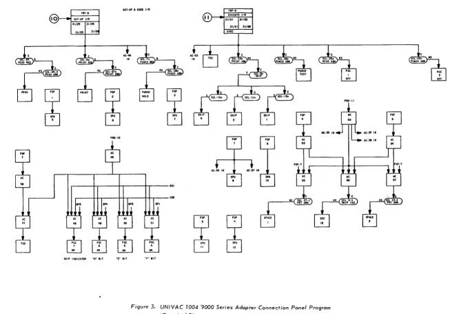
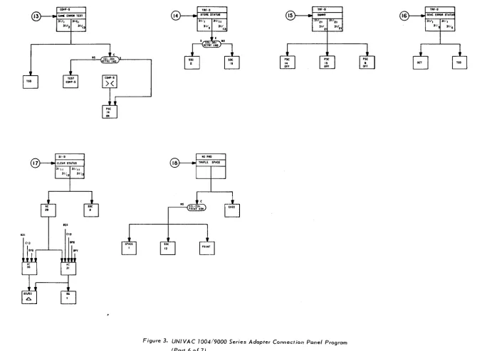
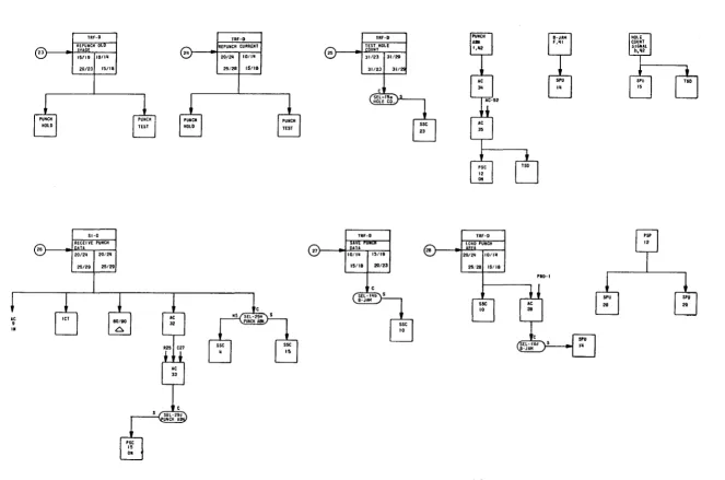
3. UNIVAC 1004/9000 Series Adapter Connection Panel Program
5
5
6
1
I
I
!1
j
I
/1
·
UP-7839 UNIVAC 9200/9200 11/9300/9300 11/9400 1004/1005 SUBSYSTEM
1. GENERAL
The UNIVAC 1004/1005 Subsystem (Figure 1) can be connected online to one of the UNIVAC 9000 Series Systems by means of one of the multiplexer
sub-PAGE:
channels and an F0943-99 Channel Adapter to provide card reading, card punching, and printing capability. This subsystem, which has arithmetic, logical, and editing capabilities, comprises independent processing units allied to a modular 961-character core storage. Standard peripheral units for this subsystem are a 400-cpm or 615-cpm card reader and a 400-lpm or 600-lpm line printer with a 63-character set and 132-character print line width. A card punch operating at 200 cpm may also be included.
A prewired connection panel provided with the channel adapter must be installed in the subsystem central processor. In the UNIVAC 1005 Subsystem, it is necessary to replace the existing connection panel with the new one.
The UNIVAC 1004/1005 Subsystem retains freestanding processing power when used online with a 9000 Series System. Therefore, the subsystem can be switched at any time to the offline mode to operate as a standard freestanding model.
For detailed descriptions of this subsystem, see UNIVAC 1004/1005 Subsystem References UP-5042, UP-2541, UP-2543, and UP-3927 (current versions).
Figure]. UNIVAC 1004/1005 Subsystem
UP-7839 UNIVAC 9200/9200 11/9300/9300 11/9400
1004/1005 SU BSYSTEM
The UNIVAC 1004/1005 Subsystem characteristics are as follows:
Card reading speed
Card punching speed
Printing speed
Printable characters per line
Number of print positions per line
Line spacing
Ma in storage capac ity
Number of input/output channels used
80-column read capability
Code i mage read
Punch stacker select
Code i mage punch
External interrupt
(Component pac kage 152)
2. OPERATION
400 or 615 cards/minute
200 cards/minute
400 or 600 lines/minute
63 plus space
132
6 or 8 lines/inch
961 storage locations (standard)
2048 or 4096 storage locations (optional)
Required if reader is used online to a
UNIVAC 9000 Series central processor
Required if punch is used online to a
UNIVAC 9000 Series centra I processor
PAG E:
Operating procedures for the subsystem and the different central processors of the UNIVAC 9200/9300 Systems and the UNIVAC 9400 System are provided as follows:
• UNIVAC 1004/1005 Subsystem with the UNIVAC 9200/9300 Systems
• UNIVAC 1004/1005 Subsystem with the UNIVAC 9400 System
2.1. UNIVAC 1004/1005 Subsystem and UNIVAC 9200/9300 System Operating Procedures
The procedures for operating the UNIVAC 1004/1005 Subsystem with a UNIVAC
9200/9300 Card Operating System are provided in 9.5 of the UNIVAC 9200/9200 Il/
9300/9300 Il Systems Card System IOCS Programmers Reference, UP-7728 (current
version). The procedures for operating the UNIVAC 1004/1005 Subsystem with a
UNIVAC 9200/9300 Tape/Disc Operating System are provided in 9.6 of UNIVAC
9200/9200 1l/9300/9300 Il Systems IOCS Programmers Reference, UP-7526
(current vers ion).
UP-7839 UNIVAC 9200/9200 11/9300/9300 11/9400
1004/1005 SUBSYSTEM
2.2. UNIVAC 1004/1005 Subsystem and UNIVAC 9400 System Operating Procedures
The procedures for operating the UNIVAC 1004/1005 Subsystem online to the central processor in the UNIVAC 9400 System are as follows:
• Device Preparation
PA GE:
Standard UNIVAC 1004/1005 Subsystem procedures should be used for peripheral device preparation in conjunction with the follow ing:
The card reader of the subsystem must be loaded with input cards before the subsystem can be initialized, even though the card reader may not be used for the current job.
The card punch should be turned on, but this is not a requirement. However, if
the card punch is used, the CHECK light on the punch front panel must be off.
The EI ENABLE (External Interrupt) switch on the subsystem must be on.
When the above conditions are met, press the CLEAR, START, FEED, and RUN switches on the subsystem •
• Device Error Recovery
Whenever an I/O error is detected on a UNIVAC 1004/1005 Subsystem device, the operator is informed by means of a console output message. For example:
hh:mm 04 SEOO xxx ABN R
where: xxx = device identification code
After a message, such as that in the preceding example, is received, the recovery procedure is as follows:
(1) Bring the subsystem to an orderly halt by typing the message:
04 ®, STOP ®
The mask panel on the subsystem then indicates to the operator what the problem is.
(2) Follow standard subsystem error recovery procedures.
(3) Upon completion of these procedures, press the RUN switch.
(4) Inform the UNIVAC 9400 Operating System (UNIVAC 1004/1005 Ha"ndler) that the I/O error has been corrected and the operations can be resumed. To do this, the following message is typed in:
04 ®, xxx R
where: xxx = device identification code.
NOTE: Operations cannot be resumed on any device until this message has been received by the UNIVAC 9400 System.
UP·7839
3.
UNIVAC 9200/9200 11/9300/9300 11/9400
1004/1005 SUBSYSTEM
DIFFERENCES BETWEEN UNIVAC 1004/1005 AND 9000 SERIES PRINTERS
The more significant differences between the printer of the UNIVAC 1004/1005 Subsystem and the printer of the UNIVAC 9000 Series System are as follows:
• Character set differences
• Skip code differences
The load code for the UNIVAC 9000 Series printer results in no operation for the 1004/1005 printer.
3.1. Character Set Differences
The standard UNIVAC 1004/1005 Subsystem printer character set contains five characters which are not available on the UNIVAC 9000 Series printers. These characters, together with their software-translated equivalent, are listed in the following table.
UNIVAC 1004/1005 UNIVAC 9000 SERIES TRANSLATED EQUIVALENT
PAG E:
PRINTER CHARACTER HEXADECIMAL CODE PRINTER CHARACTER
!\ (delta) 4A It (cents sign)
[ (left bracket) 4F
I
(absoluteJ (not equa
n
SF..., (logical not)
T
r.t (lozenge) 60 _ (underline)
] (right bracket) 7F " (quote)
""
4I
\...J
UNIVAC 9200/9200 11/9300/9300 11/9400
1004/1005
SUBSYSTEM
PAG E:3.2. Skip Code Differences
4.
The UNIVAC 1004/1005 Subsystem printer and the UNIVAC 9000 Series printer use different skip codes, whose equivalents are listed as follows:
FORM CONTROL LOOP CONTROL EQUIVALENT
9000 SERIES PRINTER 1004/1005 PRINTER
No space No space
Space 1 line Space 1 line
Space 2 lines Space 2 lines
Space 3 lines Space 3 lines
Skip 4 Skip 2
Skip 5 Skip 3
Skip 6 Skip 4
Skip 7 Skip 5
Skip 8 Skip 6
Skip 9 (from overflow) Skip 1 (form overflow)
Skip 10
Skip 11 { No 'oem " " ' ' ' " ' , ,
p''''
with these skip options for
Sk ip 12 either a wr ite or a contro I
Skip 13 command.
Skip 14 (home paper 6 Ipi) Skip 7 (home paper)
Skip 15 (home paper 8 Ipi) Skip 7 (home paper)
CONNECTION PANEL
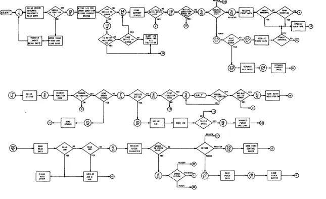
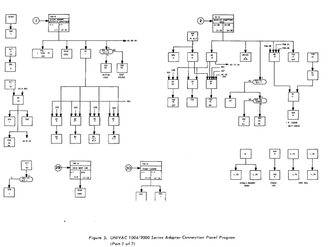
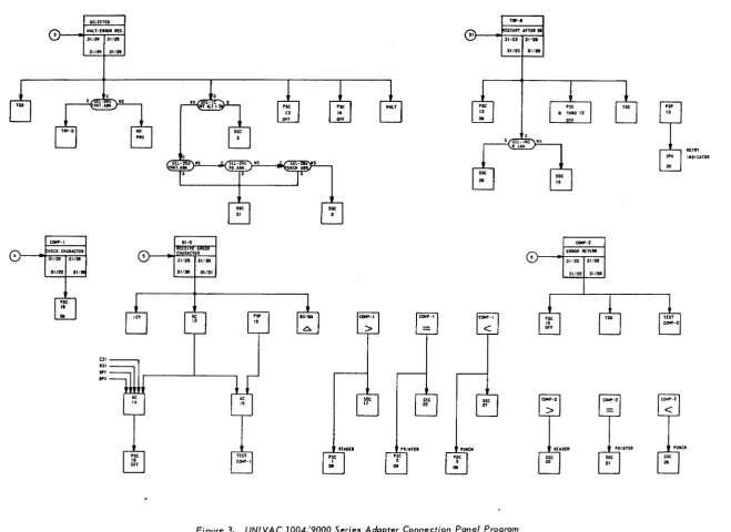
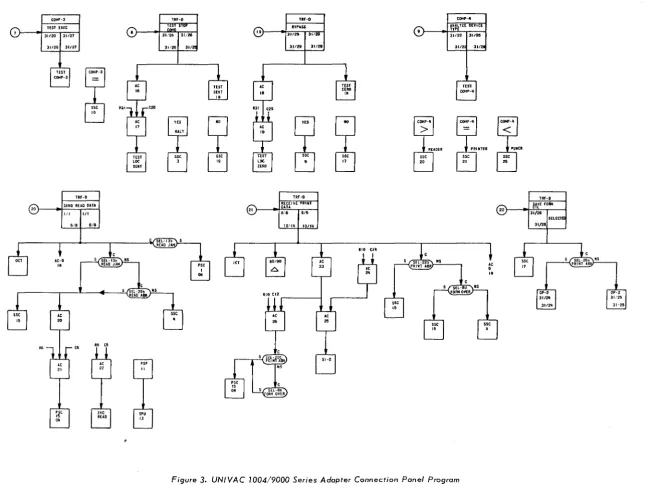
Since the connection panel is prewired at the factory, point-to-point wiring tables are not provided in this document. However, a general flowchart of the UNIVAC 1004/9000 Series Adapter (F igure 2) and a connection panel program of the UNIVAC 1004/9000 Series Adapter (Figure 3) are provided.
5
I
1
I
I
1
~
I
1
' . '.'Ii""";.' 11'··
I
l;':
. ~.l:
,:;.
(
i"" :,:' \,,'
Figure 2. UNIVA C 1004/9000 Series Adapter General Flowchart
(
(
c::
't:J
•
"
00
W
\0
.... c
oz
0
-... <
"-...>
.... 0
0 - 0 Ot.)
U1 0
o
'"
"-c:-o
OJ~ " , 0
-<=
CIt'
-I~
m
o~o
;a
11 J> o
[lI w o o
~
~
o
~
~(
INS-D CLEAR MEMORY EHERATE CONSTA,.
1/1 hll I ' l l JI'31
(
INITIAL TEST
LOAD STATUS
51-0
RECEI-vt-rifNCfiOii
CODE
31126 131126
31/30
I
31130AC-12 IN
(
r-~~--~--~--'---+----r--4---~'
e22 020 e2. 023
I '0 ERROR
UNIT CHECK
" 5 b,75 f,75 TRF-D TRF-O
MOVE BOOT LOR TRAitS LOADER
- r ; 6
~ ~
~
~
Ul ~ ~
l,32 L.311 '=0 d,75 h,75
READ ElEC
Figure 3. UNIVAC 1004/9000 Series Adapter Connection Panel Program
(Part 1 of 7)
SINGlE MEMORY BANK
POWER
IN'
1005 REO.~.
c:
'tl•
"
~.) \0 c: 0 % 0 -~<,,->
.... 01 0 " , Ot-.)
( n O 0
"''-..
C:'"
tJ:I~
" , 0
~
"III.p""" 11':"'!:' "
I.:,'
,(
Eea: CMAucnR
31/22-r 31120 31/221 31,
,se
iI
..
S(UCTED ""LT-UROR Me. 31/2fI 131/25
3112111 311n
01 .31 BP'
...
'1': ,",II II-D CHARACTER31/29 131/30
31130
I
31131Ae 13
sse
•
~D£I
'se 1
..
COMP-I
>
S . . 17 'lINTEl Pst
•
..
'1': COMP-I=
sse..
TIf-D 31) _-([START AflU01
31/23 131.$"
~CtI pse 3
..
"""'-I<
sse 2731/231 311ft
Figure 3. UNIVAC 1004/9000 Series Adopter Connection Ponel Program (Part2of7)
(
.;;
COMI"-2 ERROR REruM
31i22 131/26
311221 31/20
RETRY INDICATOR
(
c:
't1•
' I 00 W \0.... c
Oz
0
-"..<
,,~
.... 0 0 - 0
°IV
U'lo
(I'~
c:-o
gd::l
( 1 ' 0
-<=
(I'~ -Iwmg
~, 11 }> G'l 1'1 -0 ~ o~
.c..g
00 l'•
;'!'ii!r,!ii;":!'!'i~'iii'!i;::!"r .,ii!I!~!"ii
'I
'~"i "'"
COMf'-3
TEST EXEC
31/20 131/27
311201 31/27
TEST
COMP-3
TRf-D
20)
.I
SEND READ DUAI
III 1111
~
co R' co
e20
TRF-O
TESfS"
n'~ 131/26 311261 31/:
~
osse
"
(
TRf-D
19) "131~::AS~ 31/29
I
311291 31121
6
ES~0
m m
• n
TRf-D
RECEI~CPRltn
21) .,~~~" 16/6
~ sse
i'
C0'4P·II A,,-iLytCIlEVl nPE 31122 131126Figure 3. UNIVAC 7004/9000 Series Adopter Connection Panel Program
(Port 3 of 7)
Ae 9
'"
sse•
TRF-D22) "I mE fO,..
31/28 I
SELECTI
31/28
(,
c::
'tI I ~ 00, OJ \0
... c
Oz
0 _
"""<
".»
" ' 0
0 - 0 0t.)
U10
(It~
C-o
GJ~
( i t O
I
~f,i"i:~":';"I::!::' \
.r:; ;;..
/ '
~ ~.
1Ii.\. Illi:l. ""\:l"'jl'ii'iih ' ; ;~'j;'~1
;
",'"
~
:'
SPU
•
ii':
SET-lit I UK 1/0
TRF-O
SET-UP I/O
31/2'
31/2!i 311:
y
~
y
~
PRO-IO
r---4-r---~---_rr_---QI
II II II C2Ii NS
Sill' 'WOIClTOR "D" liT ~£,. liT
~
"
~
"
~r" liT
Figure 3. UNIVAC 1004,'9000 Series Adapter Connection Panel Program
(Part 4 of 7)
(
'RO-II(
c:::
'1j•
~ (Xl W \0 - cOz
0 _ 0l:I0.< ... ~on
0 - 0
U1~
" , 0 c:~ 173~
' " 0
-<-CIt,
-t-o m~ ~O ~ ~ 1)"
Gl JT1 o~
g
... :e'
o
I
I'
f"'"
I'
",:.BG
y
(')
RUD ABH INO CI
pJl
INS-D STATUS
31:21 131/1
~
PUNCH AS" INO PRT "Bill IHO
STATUS GENERATED ON ERRORS
C2
( ")
TEST I/O .I ABNORMAL ERROR STATUS
NS
fORMS OVERflOW
" - - - -FOR'~ OVERflOw
PRINTER ERROR " - - - PUNCH ERROR
READER ERROR
Figure 3. UNIVAC 1004/9000 Series Adopter Connection Panel Program (Port 5 of 7)
, - - - , , " _ _ _ ~C'"'"'_~"~ _ _ '~"~_' _ _ _ "' _ _ _ _ ~_~ __ '_' __ '''"~' _ _ _ ""_" .. "" ____ .,""C--_ ... _____ " __ "_~ ... " __ ~ •. " ... .,",._'"_
()
CHECK FOR
RIGHT PLUGBOARO
c::
'tl
•
~
W"
10
.... c OZ
C)
-. <
'-.> ... 0
0 - 0
0 " ,
UTg
!III\I""'" Ir '31
(,
TSO CI3 COIo:'·5 SI·O 31111 31'1CLf.lR STATUS
ll.'1
.31 CI3
a.a
"I"
sse
,.
TIIr·D
STOlE STATUS
NO PRO 31111
311
13
TRIPLE SPACE
,'Ii, nr·D
...,.
21 311•
.st IS OFf 21 31'21Figure 3. UNIVAC 7004/9000 Series Adapter Connection Panel Program
(Part6of7)
(.
\(
Lc:
'tI•
'-l 00 W \0 c:Oz
0 _ "..<'-...»
... 0O . g Ot-.) Vl O Cl'0
c:::a
D:I~ Cl'O -<-CI'~ -t""mo
~o 11 > Gl fTI:a
""
g
~
g
...
N .iII ('I.
r
I
(.~
TRf-D 23 51-D RECEIVE----PUHCH26 ) . , ~~;:11 I 20/211
l
25/291 25/29
(q)
TRF-O TRF-O
ID/IU 31/29
15/18 3/1
TRF-D
27) "II~~!~ I I~/Ig
I
15/18 I 20/23
TRF-O
LOAD PUNCH 28 )
"I
IREI20/2U 110/111
25.'28115/18
•• e
10
Figure 3. UNIVAC 1004/9000 Series Adapter Connection Panel Program
(Part 7 of 7)
PRO-I
__ • ______ ~--"-__ ~, •• "~ ... _'_''"_M_ .. __ ~.~ __ ._.~ ... ~:.. __ ""'"" ... __ .. _" .... _._ •.
C)
i!.mijl!~!11
, .. , ..
!:::t:~c::
"'C•
~ 00 (.oJ \0 c:oz
0-"",,<
'-....>
.... n0 " ,
~~ e "'''-C:'" CD""
",8
-<-"':::::
-t~me
~e ~ 1) » G'I (118
~
~ e
....
(.oJ
~"
•
'.
UP-7839
1
0
.~ , ~? ...
~~""'~:.~~
•. '.1:.'.~~
1
-.:.j