R E S E A R C H
Open Access
DF-based sum-rate optimization for
multicarrier multiple access relay channel
Mohieddine El Soussi
1*, Abdellatif Zaidi
2,3and Luc Vandendorpe
1Abstract
We consider a system that consists of two sources, a half-duplex relay and a destination. The sources want to transmit their messages reliably to the destination with the help of the relay. We study and analyze the performance of a transmission scheme in which the relay implements a decode-and-forward strategy. We assume that all the channels are frequency selective, and in order to cope with that, we incorporate Orthogonal Frequency-Division Multiplexing (OFDM) transmission into the system. In contrast to previous works, both sources can transmit their messages using all subcarriers and the relay can decide to help none, only one, or both sources. For this scheme, we discuss the design criteria and evaluate the achievable sum-rate. Next, we study and solve the problem of resource allocation aiming at maximizing the achievable sum-rate. We propose an iterative coordinate-descent algorithm that finds a solution that is at least a local optimum. We show through numerical examples the effectiveness of the algorithms and illustrate the benefits of allowing both sources to transmit on all subcarriers.
Keywords: Relay channel; Decode-and-forward; OFDM; Optimization
1 Introduction
Relaying has been introduced to extend system coverage, enhance spectrum efficiency, and improve the perfor-mance of wireless systems. Cooperative relay networks have been studied extensively for many wireless systems [1-3]. In a typical relay system, the relay helps the trans-mitters by forwarding the transmitted messages to the destination. Different efficient relaying protocols have been proposed in the literature, including amplify-and-forward (AF), decode-and-amplify-and-forward (DF), and compress-and-forward (CF) [2,4]. Each protocol has its advantages and its disadvantages; and which scheme outperforms the others depends on the network topology and chan-nel conditions. Capacity bounds and rate regions have been established in [5] for the standard three-terminal Gaussian relay channel and in [4,6] for the Gaussian mul-tiple access relay channel (MARC). The reader may also refer to [7-9] for some related works.
In the context of cooperative communication, mul-ticarrier transmission techniques, such as the popular Orthogonal Frequency-Division Multiplexing (OFDM)
*Correspondence: [email protected]
1ICTEAM, Université catholique de Louvain, Place du Levant, 2, 1348 Louvain-la-Neuve, Belgium
Full list of author information is available at the end of the article
and its multiuser version Orthogonal Frequency-Division Multiple Access (OFDMA), constitute promising tools that can offer high data rate. In particular, this is due to the fact that these techniques permit to handle frequency selectivity and harness multiuser diversity. Essentially for these reasons, these techniques have been adopted in most next-generation wireless standards and are generally considered in the context of relay-aided communications in frequency selective channels.
In this paper, we consider communication over a mul-ticarrier two-source multiaccess channel in which the transmission is aided by a relay node, i.e., a multicarrier two-source MARC. The communication takes place over two transmission periods or time slots. The sources trans-mit only during the first transmission period. The relay is half-duplex, implements the decode-and-forward pro-tocol, and transmits only during the second transmission period. We propose a multicarrier transmission scheme based on OFDM where, in contrast to the OFDMA scheme [10], each subcarrier can be used by both sources simultaneously. In this paper, we refer to this scheme as OFDM for convenience. For this scheme, we derive the achievable sum-rate. Also, we study the problem of allocating the resources and selecting the relay operation mode (i.e., active or idle) optimally in order to maximize
the obtained sum-rate. Some of the key issues that we consider are related to the selection of appropriate relay operation mode for every subcarrier and the allocation of power at the two sources and at the relay.
1.1 Literature overview
For a point-to-point OFDM transmission aided by a DF relay node, some resource allocation algorithms have been proposed and studied in the literature. For example, in [11], the authors investigate the problem of maximizing the sum-rate. Depending on the fading coefficients, on each subcarrier, the relay node can be either idle or active. If the relay is idle, the source transmits a new indepen-dent symbol in the second time slot. This transmission protocol is extended for the scenarios in which the trans-mission involves multiple relays, and the related resource allocation problems are solved in [12-14]. The problem of resource allocation over a two-way DF relayed channel has been investigated as well in [15,16].
For OFDMA systems that involve relays, some related contributions have been proposed in the literature. These include [17] and [18], in which the authors consider respectively the maximization of the achievable sum-rate and the maximization of a weighted sum goodput. In [19], the authors jointly optimize the relay strate-gies and physical-layer resources in a multiuser network, where each user can act as a relay. In [20] and [21], the authors study capacity regions of OFDMA multi-ple access networks that comprise AF and DF relays. They also investigate a problem of subcarrier assign-ment for given powers at the sources and the relay. The reader may also refer to [22-24] for some related works.
For multiaccess relay networks, in [7], the authors inves-tigate a problem of power allocation for ergodic fading orthogonal MARC in which two sources communicate with a destination and with the help of a half-duplex relay. The authors show that the sum-rate belongs to one of the different cases and they optimize the power allocation in order to maximize the sum-rate for all the cases. In comparison with our setting, their relay uses non-regenerative DF [22] where it transmits, dur-ing the second transmission period, to the destination a codeword independent from the ones transmitted by the sources. However, in our setting, the relay estimates the symbols sent by the sources and then forwards them to the destination, i.e., the relay implements regenera-tive DF [22] in which the relay uses the same code-book as that used by the sources, and thus, it transmits the same codewords as those sent by the sources. For this reason, the decoding method and the achievable sum-rate are different. Hence, the problem formulation and the corresponding resource allocation are different as well.
The setting that we consider is connected to [10] where the authors study the problem of resource allo-cation for a multiuser relay network with orthogonal channel access that uses OFDMA. They consider dif-ferent relay strategies and maximize the sum-rate under individual power constraint. However, the setup in [10] does not consider the case in which the sources are allowed to transmit their messages using the same subcarrier. In the current work, we show the advan-tage of allowing both sources to transmit on all subcarriers.
1.2 Contributions
is decoded at the destination at the same subcarrier in a different transmission period.
For the multicarrier transmission scheme that we con-sider, we study and solve the problem of maximizing the offered sum-rate under individual power constraints. The optimization problem consists of i) selecting the appro-priate relay operation mode (i.e., helping none, only one, or both sources simultaneously) for every subcarrier, ii) choosing the best decoding orders at the relay (if active) and the destination for every subcarrier, and iii) allocating the powers on each subcarrier and transmitting termi-nal. The resulting optimization problem is mixed-integer program since some of the variables are constrained to be integers, while other variables are allowed to be non-integers, and so, it is not easy to solve it optimally. We propose an iterative algorithm that is based on a coor-dinate descent approach and that, for every subcarrier, finds the best relay operation mode and decoding orders at the relay (if active) and the destination, and appropriate powers for the terminals transmitting on that subcar-rier, alternately. The iterations stop when convergence to a stationary point is obtained. For given relay operation mode and decoding orders combination, the problem of allocating the powers appropriately is non-convex and non-linear. Since optimally solving this problem is diffi-cult, we propose an algorithm that is based on geometric programming approach and a successive convex approxi-mation method [25] and that provides a solution that is at least a local optimum.
Our analysis shows that by allowing the sources to possibly transmit on the same subcarrier simultaneously, one can afford a larger sum-rate, i.e., the OFDM-based transmission scheme offers a substantial sum-rate gain over the one that is based on OFDMA. The analysis also shows the convergence of the proposed algorithm with a
reasonable complexity. We illustrate our results through some numerical examples.
1.3 Outline and notation
An outline of the remainder of this paper is as follows. Section 2 describes in more details the system model that we consider in this work. Section 3 contains some known results from the literature for the setup under considera-tion where the sources transmit on orthogonal channels, i.e., using OFDMA transmission scheme. In Section 4, we analyze the sum-rate that is achievable using the OFDM scheme. Section 5 contains the optimization problem as well as the algorithms that we propose. In Section 6, we consider an improvement to the transmission schemes described in this work. Section 7 contains some numerical examples, and Section 8 concludes the paper.
The following notations are used throughout the paper. Lowercase boldface letters are used to denote vectors, e.g., x. Calligraphic letters designate alphabets, i.e.,X. The car-dinality of a setX is denoted by|X|. For vectors, we write x∈An, e.g.,A=RorA=C, to mean thatxis a column vector of sizen, with its elements taken from the set A. For a vectorx∈Rn,xdesignates the norm ofxin terms of Euclidean distance. We use [x]+ to denote max{0,x}. Finally, for a complex-valued numberz = x+ jy ∈ C, the notations Re{z} and Im{z} refer respectively to the real part and imaginary part of z ∈ C, i.e., Re{z} = x and Im{z} = yand the notationz∗refer to the complex conjugate ofz, i.e.,z∗=x−jy.
2 System model
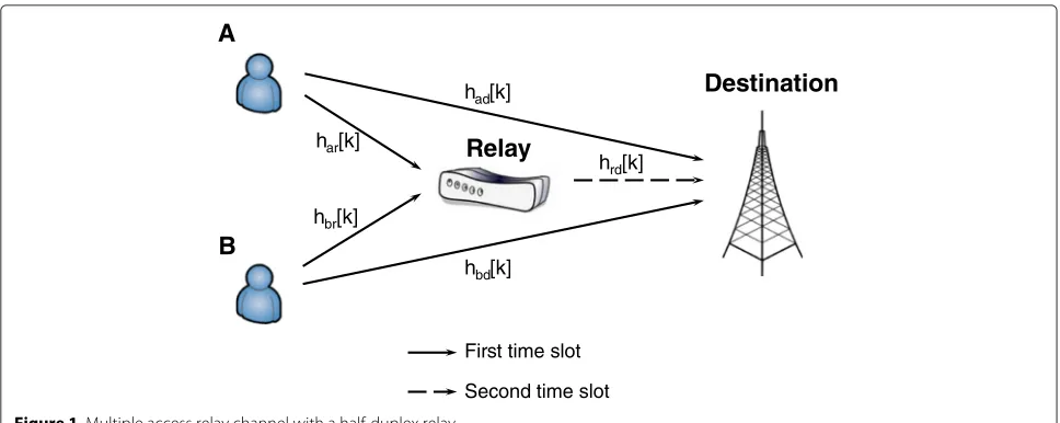
We consider a multiaccess relay network that comprises two sources (AandB), a relay node (R) and a destination (D), as shown in Figure 1. The sourcesAandBwant to transmit their messages,Wa ∈ WaandWb ∈Wb, to the
A
B
Relay
had[k]hrd[k]
hbd[k] har[k]
hbr[k]
First time slot
Second time slot
Destination
destination with the help of the relay. The relay is half-duplex and implements a regenerative DF strategy. The communication takes place in 2n channel uses (n is the number of channel uses required to transmit a codeword) and is divided into two periods or time slots with equal durations. All the channels are assumed to be frequency selective, and in order to cope with that, we incorporate OFDM transmission into the system. As usually assumed in similar settings, we assume that appropriate cyclic pre-fix is employed, turning the channel into a number of parallel subchannels.
There are in total K subcarriers that can be used by the sources for the transmission. In the OFDM-based transmission, both sources transmit simultaneously on the same subcarrier k. The encoding and transmission scheme on subcarrierk, 1≤ k ≤Kis as follows. During the first transmission period, sourceAtransmits the code-wordxa[k] over the channel. Similarly, sourceBtransmits the codewordxb[k] over the channel. During this period, the outputs at the relay and the destination on subcarrier kare given by
yr[k]=har[k]xa[k]+hbr[k]xb[k]+zr[k]
yd[k]=had[k]xa[k]+hbd[k]xb[k]+zd[k] , (1)
wherehar[k] andhbr[k] are the channel gains on the links
to the relay;had[k] andhbd[k] are the channel gains on
the links to the destination; the vectorzr[k] is the additive noise at the relay, and the vectorzd[k] is the additive noise at the destination. These noise vectors, on subcarrierk, are mutually independent and are independently and identi-cally distributed (i.i.d) with components drawn according to the circular complex Gaussian distribution with zero mean and varianceN.
Assuming that it decodes correctly the codewords transmitted by the sources, during the second transmis-sion period the relay re-encodes the codewords using the same codebook employed by the sources. Thus, during this period, the output at the destination on subcarrierk is given by
˜
yd[k]=hrd[k]x˜r[k]+ ˜zd[k] , (2)
wherehrd[k] is the channel gain on the link to the
destina-tion; and the vectorz˜d[k], on subcarrierk, is the additive noise at the destination during this period, assumed to be independent from all other noise vectors and i.i.d. with components drawn according to a circular complex Gaussian distribution with zero mean and variance N. We should note that the relay signals the destination if one or two codewords are forwarded through the control information.
Throughout the paper, we assume that the carrier fre-quency and symbol timing of the sources are perfectly synchronized at the relay and the destination. Also, we
assume that the states of the channel are known per-fectly to all terminals in which they can be estimated at the receivers and fed back to the transmitters. Thus, we assume perfect channel state information at the receivers (CSIR) and perfect channel state information at the trans-mitters (CSIT), and that these CSIs remain constant over a transmission period. We also assume that we have perfect decoding at the relay and the destination.
Furthermore, the noise signals at the relay and the desti-nation are independent from each other and i.i.d circular complex Gaussian, with zero mean and varianceN. Also, we consider the following individual constraints on the transmitted power, imposed on the system;P ≥ 0 is given. The constraints in (3) are the total power used by sourceA, sourceB, and relayR, respectively, during the whole transmission. For convenience, let βa[k]≥ 0 andβb[k]≥ 0 be non-negative scalars such that βa2[k]P and βb2[k]P be the powers used at sourceA and sourceBon subcarrier k, respectively. Similarly, let βr[k]≥ 0 be a non-negative scalar such that βr2[k]P be the power used by relay R on subcarrierk. Also, let βar2[k]P be the fraction of the power that the relay uses to help sourceA, andβbr2[k]P be the fraction of the power that the relay uses to help source B, with β2
ar[k]+βbr2[k]= βr2[k]. Finally, we will sometimes use the shorthand vector notation β[k]= [βa[k] ,βb[k] ,βar[k] ,βbr[k] ]T ∈R4.
3 Achievable sum-rate using OFDMA transmission
In this section, we present the achievable sum-rate for the MARC model that we study using the OFDMA transmis-sion scheme [10].
achievable sum-rate for the OFDMA transmission scheme
We should note that to maximizeROFDMAsum , we need to properly allocate the subcarriers among the two sources and allocate the powers per subcarrier at the sources and the relay. For that, we use (Algorithm 2, [10]) to allocate the subcarriers and (Algorithm 4, [10]) to allocate the powers. These algorithms will be used for comparisons in Section 7.
4 Sum-rate analysis for the OFDM-based transmission
In this section, we describe and analyze the OFDM multi-carrier transmission scheme from the achievable sum-rate viewpoint.
The following proposition provides an achievable sum-rate for the multiaccess relay model of Figure 1, using OFDM multicarrier transmission.
Proposition 1.For given channel states {har[k] , hbr[k] ,had[k] ,hbd[k] ,hrd[k]}Kk=1, the following sum-rate is achievable for the multiaccess relay channel of Figure 1:
(P1) : ROFDMsum =max Definition 1 in Appendix 1; the outer maximization is over {β[k]}Kk=1, with β[k]=[βa[k] ,βb[k] ,βar[k] ,βbr[k] ]T, such thatKk=1βa2[k]P ≤ Pa, Kk=1βb2[k]P ≤ Pb, and
K
k=1(βar2[k]+βbr2[k])P≤Pr.
The proof of (P1) can be found in Appendix 2. The following remark reveals certain aspects related to the
coding scheme and is useful for a better understanding of the proof and its structure.
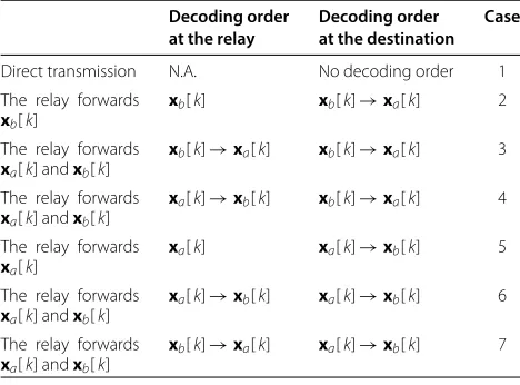
Remark 1.In this scheme, in contrast to the OFDMA scheme, both sources are allowed to simultaneously trans-mit on every subcarrier. The relay is half-duplex and implements regenerative decode-and-forward strategy on the symbols transmitted on each subcarrier. It can decide to help none, only one, or both sources simultaneously. If, for a given subcarrier, the relay helps both sources, it decodes the sources’ codewords successively. Then, on the same subcarrier, it shares its power among the two code-words and superimposes the information that is intended to help source A and the one that is intended to help source B. The destination, using what it receives dur-ing the two transmission periods, decodes the sources’ codewords successively, and the decoding operations are based on maximum-ratio combining. Different decoding orders combinations (at the relay, if applicable, and at the destination) generally result in different achievable sum-rates, and the selection of the appropriate decoding order depends on the fading coefficients and the allocated power. In addition to the decoding orders at the relay and the destination, the relay operation mode (i.e, helping none, only one, or both sources) influences the achievable sum-rate. This leads to 13 different cases if all possible combinations are considered using the decoding orders and the relay operation modes. However, it can be shown that whenever the relay helps only one of the sources (by decoding and forwarding the codeword transmitted by that source), this codeword should be decoded first at the destination. When the relay helps the two sources simul-taneously, a total of four possible decoding orders need to be investigated and compared (two possible decoding orders at the destination for each possible decoding order
Table 1 Different useful cases for the OFDM multicarrier transmission
Decoding order Decoding order Case at the relay at the destination
at the relay). Hence, out of the 13a prioripossible cases only 7 actually are of interest. These cases are summa-rized in Table 1, and their corresponding sum-rates,Rl[k], 1≤l≤7, are given in Definition 1.
Remark 2.The greatest advantage of the OFDM scheme of (P1) over the OFDMA scheme lies in the cases where the relay helps only one of the sources, i.e., case 2 and case 5. In these cases, one of the sources is clustered with the relay, i.e., it is close to the relay and far from the destina-tion; the other one is clustered with the destination, i.e., it is close to the destination and far from the relay. To illus-trate this point, we consider a scenario where each source has a strong link and a weak link. Let us suppose that, without loss of generality, sourceAhas a strong relay link, i.e., it is close to the relay, and a weak direct link, i.e., it is far from the destination, and sourceBhas a weak relay link and a strong direct link. This means that, during the two transmission periods and by allowing the sources to simultaneously transmit on the same subcarrier, sourceA communicates with the destination through the relay link and sourceBcommunicates with the destination through the direct link. Note that the interference generated by source Aon the direct link is small since source Ahas a weak direct link. Similarly, the interference generated by sourceBon the relay link is small since sourceBhas a weak relay link. Thus, using the proposed scheme, the optimal policy for sourceAand sourceBcan be approx-imated to be a water-filling solution over all subcarriers to the relay and to the destination, respectively, and the optimal policy for the relay can be approximated to be a water-filling solution over all subcarriers to the desti-nation. On the contrary, using the OFDMA scheme, the optimal policy for each source is a water-filling solution over the allocated subcarriers. Therefore, the proposed scheme uses the two transmission periods to serve both sources, and each source has access to a larger container (subcarriers) during the water-filling solution which yields a higher sum-rate compared with the OFDMA scheme. As a result, the proposed scheme has a larger degree of freedom compared with the OFDMA scheme. This is illustrated through some numerical examples as shown in Section 7.
Remark 3.We should note that the OFDM scheme of (P1) always outperforms the OFDMA scheme, and in worst case scenario, it has the same performance. This can be verified by investigating the achievable sum-rate of both schemes. It can easily be seen that the optimum power policy {β[k]}Kk=1 obtained by maximizing the sum-rate of the OFDMA scheme yields the same sum-rate if it is used with the OFDM scheme. Thus, the OFDMA transmission scheme acts as a lower bound for the OFDM transmission scheme.
Remark 4.As described in Remark 1, there exist seven cases for the two-source MARC. However, in order to decrease the computational complexity, we can consider only three cases (1, 2, and 5) and still benefit from the larger degree of freedom (e.g., see Remark 2). We should note that by considering cases 1, 2, and 5, the complexity is dramatically reduced with the expense of a lower trans-mission sum-rate in some regimes as we will see in the numerical examples in Section 7.
Remark 5. The system model that we study can be extended to the case of multiple sources. This can be done by allocating a subcarrierkto only two sources, the first source is close to the relay and the second source is close to the destination. This means that only cases 2 and 5 are considered. In this way, we can benefit from a larger degree of freedom, decrease the complexity, and achieve a larger sum-rate as explained in Remark 2.
5 Sum-rate optimization
In this section, we study the problem of maximizing the offered sum-rate given in (5) under individual power con-straints. The optimization problem comprises i) selecting the appropriate relay operation mode (i.e., helping none, only one, or both sources simultaneously) for every sub-carrier, ii) choosing the best decoding orders at the relay (if active) and at the destination for every subcarrier, and iii) allocating the powers on each subcarrier at the transmit-ting terminals. In what follows, we study the optimization problem in its general form, i.e., considering the seven cases; however, this can be modified to the situation where less cases are considered.
5.1 Problem formulation
Consider the sum-rateROFDM
sum as given by (5) in (P1). The
optimization problem can be equivalently stated as
(A) : max K
k=1 7
l=1
al[k]Rl[k] , (6)
for 1≤k≤K, 1≤l≤7, andal[k] is an indicator whose value should be 0 or 1, and Rl[k] is defined as in Defi-nition 1; the maximization is over{β[k]}Kk=1, satisfying
K
k=1 β2
a[k]P≤Pa, K
k=1 β2
b[k]P≤Pb, K
k=1
β2
ar[k]+βbr2[k]
P≤Pr,
(7)
and over {a[k]}Kk=1, with a[k]=[a1[k] ,a2[k] ,. . ., a7[k] ]T, such that
The optimization problem (A) is a mixed-integer pro-gram, and, so, it is not easy to solve it optimally. We propose an iterative optimization where we find the appropriate powers{β[k]}Kk=1and indicators{a[k]}Kk=1, alternately. We should note that the selection of{a[k]}Kk=1 determines the decoding orders at the relay and the des-tination, and the relay operation mode (i.e., helping none, only one, or both sources simultaneously).
Let us, with a slight abuse of notation, denote by ROFDMsum [ι] the value of the sum-rate at some iterationι ≥ 0. We develop the following iterative algorithm ‘Algorithm IP’ to allocate the indicators and the powers alternately in such a way thatROFDMsum is maximized.
Algorithm IP Iterative algorithm for computingROFDM sum as
given by (5)
1: Initialization: setι=1
2: Set{β[k]= β(ι−1)[k]}K
k=1 in (6), and solve the obtained
problem as we will describe in Section 5.2. Denote by {a(ι)[k]}Kk=1the found{a[k]}Kk=1
In ‘Algorithm IP’, we compute the power values given by{β[k]}Kk=1and the indicator values given by{a[k]}Kk=1, alternately. More specifically, at iterationι ≥1, the algo-rithm computes appropriate indicator values{a(ι)[k]}Kk=1 that maximize (6) with the choice of the power values
{β[k]}Kk=1set to their values obtained from the previous iteration, i.e.,{β[k]=β(ι−1)[k]}Kk=1(for the initialization, we set{β(0)[k]}Kk=1according to a uniform power alloca-tion). This subproblem is an integer linear program (ILP) problem [26] and can be solved by selecting the case that yields the largest sum-rate Rl[k], 1 ≤ l ≤ 7, on each subcarrierk. Next, the power values{β(ι)[k]}Kk=1can be computed in order to maximize (6) with the choice of
{a[k]= a(ι)[k]}Kk=1. This subproblem can be formulated as a complementary geometric programming problem that is an intractable nondeterministic polynomial-time (NP)-hard problem. To obtain a solution for the power values {β(ι)[k]}Kk=1, we use a successive convex opti-mization approach and a geometric programming (see ‘Algorithm P’ below). The iterative algorithm (‘Algorithm IP’) terminates if|ROFDMsum [ι]−ROFDMsum [ι− 1]| is smaller than a prescribed small strictly positive constant1- in
this case, the maximized sum-rate is ROFDMsum [ι] and is attained using the power values{β[k]=β(ι)[k]}Kk=1and indicator values{a[k]=a(ι)[k]}Kk=1.
In the following two sections, we study the aforemen-tioned two subproblems of problem (A) and describe the proposed algorithms.
5.2 Indicator allocation
In this section, we aim at finding the indicator values
{a[k]}Kk=1for a given choice of power values{β[k]}Kk=1. The objective function in (6) can be stated as
max a subcarrierk, can be obtained by investigating the sum-rateRl[k] for 1≤l≤7. The indicatora[k] is calculated in such a way that the largest sum-rateRl[k] is selected, and it is given by
al[k]=
1,l=arg max1≤l≤7 Rl[k] 0, otherwise.
Hence, the largest sum-rate at subcarrrierkis
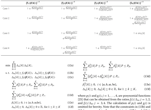
Table 2 Useful functions for the analysis of the cases described in Section 4 mization variables and the objective function. Also, it is easy to see that the power values{β[k]}Kk=1that achieve the minimum value ofKk=1a[k]b[k] also achieve the maximum value of the objective function in (6).
The optimization problem (12) is linear and non-convex. Thus, it is not easy to obtain the optimum solution with reasonable complexity. We consider geometric pro-gramming (GP) to obtain a solution for{β[k]}Kk=1. GP is a special form of convex optimization for which efficient algorithms have been developed [25,27].
We can rewrite the optimization problem (12) as
min omitted for brevity. Note that the constraints in (13b) and (13c) correspond to the constraints in (12b) and (12c), respectively.
The constraints in (13b) and (13c) contain functions that are non-posynomial since a ratio of two posynomi-als is in general not a posynomial [27]. Minimizing or upper bounding a ratio between two posynomials belongs to a class of non-convex problems known as complemen-tary GP (CGP) [25]. Complemencomplemen-tary GP is an intractable NP-hard problem. Since optimally solving this problem is difficult, we propose a method that provides a solution that is at least a local optimum. In this method, we find the power vectors{β[k]}Kk=1by series of approximations each of which can be solved in an efficient way. This means that the power vectors{β[k]}Kk=1are obtained first by turning CGP into GP by approximating the denominator of the ratio of posynomials,gj(β[k] ,i[k]), with a monomial ˜
[27] since all the conditions for convergence (section IV.A, [27]) are satisfied. Thus, we find the power vec-tors{β[k]}Kk=1by solving a series of GPs. Each GP in the iteration loop tries to improve the accuracy of the approx-imation to a particular minimum in the original feasible region. We should note that we use (Lemma 1, [27]) to approximate the posynomial functiongj(β[k] ,i[k]) with a monomial functiong˜j(β[k] ,i[k])around some initial value.
The solution of the problem obtained using the convex approximations is also solution for the original problem (13), i.e., satisfies the Karush-Kuhn-Tucker (KKT) condi-tions of the original problem [27].
Algorithm PPower allocation
1: Set β(0)[k]K
k=1 to an initial value. Compute
7: Solve the resulting approximated GP problem using an interior point approach. Denote the found solutions as
In this section, we consider an improvement to the two transmission schemes described in Sections 3 and 4. In the improved transmission scheme, the sources, in addition to the transmitted messages during the first transmis-sion period, transmit new independent messages during the second transmission period whenever the relay is idle (not active). This means that, in the OFDM trans-mission scheme, sourceA, on subcarrier k, transmits a codewordxa[k] during the first transmission period and then transmits a new independent codewordx˜a[k] dur-ing the second transmission period. Similarly, source B
transmits a codewordxb[k] during the first transmission period and then transmits a new independent codeword
˜
xb[k] during the second transmission period. Hence, the achievable sum-rate for case 1 defined in Definition 1 can be rewritten as
Similarly, for the OFDMA transmission scheme, when-ever the relay is not active on subcarrier k, the source transmits a new independent message during the sec-ond transmission period. The achievable sum-rate for the OFDMA transmission scheme can be rewritten as
ROFDMAsum =
The optimization problem to maximize the sum-rate with the improved OFDM transmission scheme can be formulated and solved using the algorithm described in Section 5. This can be done by replacing the sum-rate of case 1 (R1[k]) given in (16) by the one given in (14).
Similarly, the optimization problem to maximize the sum-rate of the improved OFDMA transmission scheme can be solved using the ‘Algorithm 2’ and ‘Algorithm 4’ as described in [10].
7 Numerical examples
relay to the destination. Similar assumptions and nota-tions are used for the direct links from the sources to the destination. The frequency response{har, hbr},{had, hbd},
and{hrd}are computed by taking K-points fast Fourier transform of the CIRs. Furthermore, we assume that, at every time instant, all the nodes know, or can estimate with high accuracy, the values taken by the channel coef-ficients,{har, hbr, had, hbd, hrd}, at that time, i.e., CSIs are
assumed to be perfectly known. Also, we setPa = Pb = Pr =P=20 dBW.
In order to illustrate the theoretical analysis and the effectiveness of the OFDM transmission scheme of (P1), we compare it with the OFDMA transmission scheme. To maximize the sum-rate of the OFDMA scheme, we use (Algorithm 2, [10]) to allocate the subcarriers and (Algorithm 4, [10]) to allocate the powers. Recall that OFDMA-based scheme allows only one source to trans-mit on each subcarrier. On the contrary, OFDM-based scheme does not have such a restriction and it allows the sources to transmit on all subcarriers.
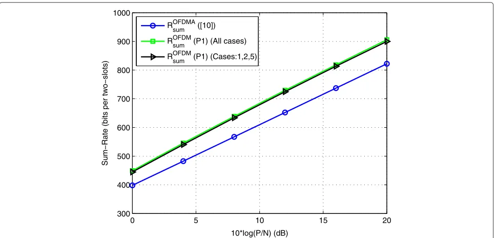
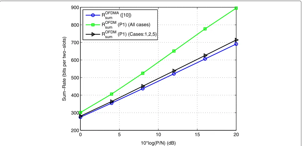
Figure 2 depicts the sum-rate obtained using the OFDMA transmission scheme of [10], i.e.,ROFDMAsum ([10]), and the sum-rate obtained using the OFDM transmission scheme of (P1) under different levels of complexity: i) all the decoding orders and all the relay operation modes are considered, i.e.,ROFDMsum (All cases), ii) only the cases where the decoding orders are the same at the relay and the destination, and the relay helps none or one source are considered, i.e.,ROFDMsum (Cases 1,2,5). The sum-rates are taken as functions of 10 log(P/N)(in decibels). We should
note that the curves correspond to numerical values of channel coefficients chosen such thatσ2
ar =σbr2 =20 dB,
σ2
rd=20 dB, andσad2 =σbd2 =20 dB.
For the example shown in Figure 2, we observe that the transmission scheme of (P1) outperforms the transmis-sion scheme of [10] in terms of sum-rate. Also, we observe that the transmission scheme of (P1) considering all cases and the transmission scheme of (P1) considering cases ‘1, 2, 5’ give almost the same performance in terms of sum-rate. However, it can easily be seen that the complexity of the latter is less than that of the former since in the latter, we only consider three cases instead of seven cases.
Figures 3 and 4 depict the same curves for other com-binations of channel coefficients. We observe that the gap between the transmission scheme of (P1) and the trans-mission scheme of [10] in Figure 3 is larger compared to the gap shown in the other figures (related to this aspect, recall the discussion in Remark 2). For the example shown in Figure 3, we can observe that since the source-relay link of sourceAis 26 dB stronger than the source-relay link of sourceBand the source-destination link of sourceBis 26 dB stronger than the source-destination link of sourceA, both sources can reliably transmit their messages using all the subcarriers during the two transmission periods with a small interference. This explains the reason why the sum-rate of (P1) is much larger than the sum-sum-rate of [10] and shows the advantage of the OFDM scheme given in (P1) over the OFDMA scheme. Also, we notice that the OFDM scheme has higher degree of freedom compared with the OFDMA scheme.
0 5 10 15 20
300 400 500 600 700 800 900 1000
10*log(P/N) (dB)
Sum−Rate (bits per two−slots)
ROFDMAsum ([10])
ROFDMsum (P1) (All cases)
ROFDMsum (P1) (Cases:1,2,5)
Figure 2Sum-rate comparison. Numerical values areK=128,σ2
0 5 10 15 20 400
500 600 700 800 900 1000 1100 1200 1300 1400
10*log(P/N) (dB)
Sum−Rate (bits per two−slots)
ROFDMA
sum ([10])
ROFDM
sum (P1) (All cases)
ROFDM
sum (P1) (Cases:1,2,5)
Figure 3Sum-rate comparison. Numerical values areK=128,σar2=26 dB,σbr2 =0 dB,σrd2 =20 dB,σad2 =0 dB, andσbd2 =26 dB.
In Figures 2 and 3, we notice that the sum-rate of (P1) considering all cases and the sum-rate of (P1) consider-ing cases ‘1, 2, 5’ yield the same sum-rate. However, we can see that, in Figure 4, the sum-rate of (P1) consid-ering cases ‘1, 2, 5’ is smaller than the sum-rate of (P1) considering all cases and slightly better than the sum-rate of [10]. This can be explained by investigating the channel strength of the different links. We can see that
both sources have a strong source-relay link and a weak source-destination link. Hence, using case 2, the transmit-ted symbol of sourceBencounters high interference at the relay due to the transmitted symbol of sourceA. There-fore, source A must transmit its symbol with a power much lower than the one of sourceB. Since sourceAhas a weak source-destination link, the destination will decode the message of sourceAat a small rate. Similarly, we can
0 5 10 15 20
200 300 400 500 600 700 800 900
10*log(P/N) (dB)
Sum−Rate (bits per two−slots)
ROFDMA
sum ([10])
ROFDM
sum (P1) (All cases)
ROFDM
sum (P1) (Cases:1,2,5)
Figure 4Sum-rate comparison. Numerical values areK=128,σ2
see that using case 5, sourceBmust transmit its symbol with a power much lower than the one of sourceAand the destination will decode the message of sourceBat a small rate. Hence, the OFDM transmission scheme of (P1) using only cases ‘1, 2, 5’ has a performance similar to that of the OFDMA scheme of [10]. Nevertheless, by considering dif-ferent decoding orders at the relay and the destination, we can observe that the OFDM transmission scheme of (P1) considering all cases outperforms the OFDMA scheme of [10] as shown in Figure 4. Also, in Figure 4, we notice that different decoding orders yield different sum-rates.
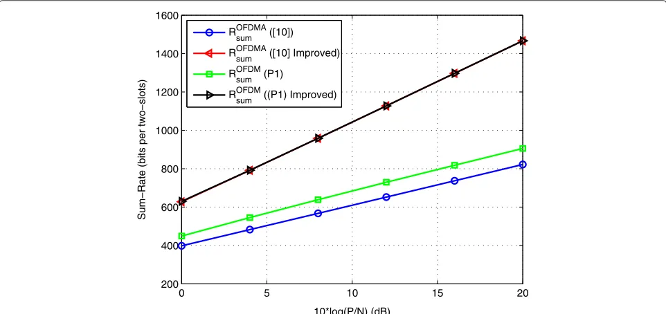
Figures 5, 6, and 7 depict the sum-rate obtained using the OFDMA transmission of [10], i.e., ROFDMAsum ([10]), the sum-rate obtained using the improved version of OFDMA transmission of [10] given in (15), i.e.,ROFDMAsum ([10] Improved), the sum-rate obtained using the OFDM transmission scheme of (P1) considering all the cases, i.e., ROFDM
sum (P1), and the sum-rate obtained using the
improved version of OFDM transmission scheme of (P1) considering all the cases, i.e.,ROFDM
sum ((P1) Improved).
In Figure 5, we can observe that both improved trans-mission schemes have the same performance and that both outperform the other transmission schemes. Since all links have same channel variances (σ2), it is more ben-eficial to allow the sources to transmit during the two transmission periods through the direct link than to trans-mit during only the first transmission period through the relay link [11]. Therefore, both improved schemes yield the same performance.
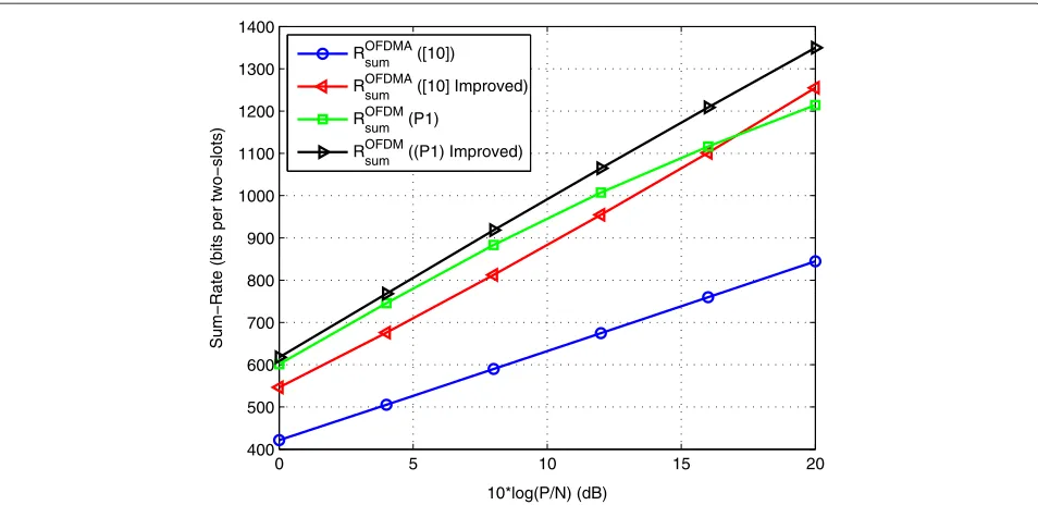
In Figures 6 and 7, we observe that the improved OFDM scheme outperforms the other schemes. Also, we observe
that, in Figure 6, the OFDM scheme of (P1) outperforms the improved OFDMA scheme of [10] between 0 and 16 dB. This means that, in this interval, it is better to use the relay link in parallel with the direct link (i.e., case 2 or case 5) than to use the direct link during the two transmis-sion periods (related to this aspect, recall the discustransmis-sion in Remark 2). We also observe how much improvement the improved OFDMA scheme brought compared with the OFDMA scheme.
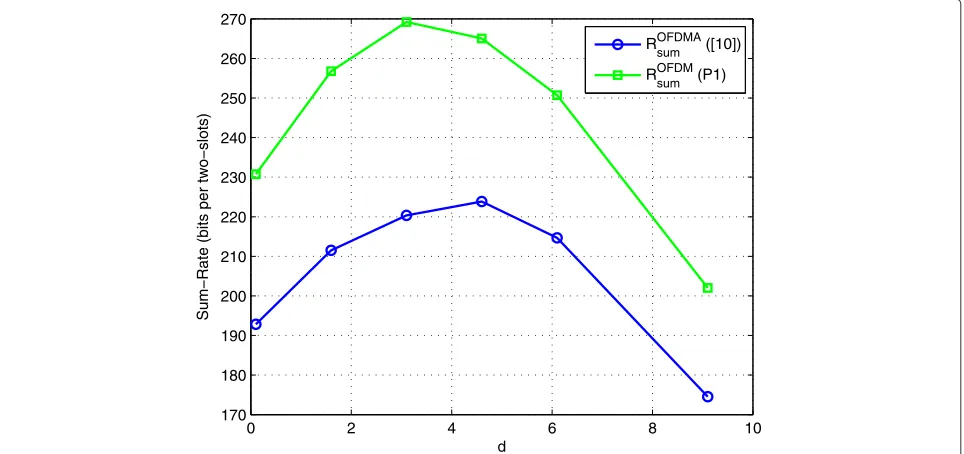
In Figure 7, we observe that the improved OFDM scheme of (P1) and the OFDM scheme of (P1) have the same performance. Since the source-relay link and the relay-destination link are stronger than the source-destination link, it is more beneficial to use the relay link in parallel with the direct link (i.e., cases 2 to 7) than to use the direct link during the two transmission periods. How-ever, for the OFDMA scheme, it is still more beneficial to use the direct link during the two transmission periods than to use the relay link, especially at high values ofP/N. Moreover, we consider the model shown in Figure 8, and we study the performance of the two transmission schemes as functions of the relay position d. For this model, we set the number of subcarriers to K = 128.
The CIR between node i and node j is modeled as a
delay line with lengthL= 32 taps. The taps are assumed to be i.i.d circular complex Gaussian distributed with zero mean and variance dij−3, where dij is the distance between nodes i andj. Also, we set 10 log(P/N) = 40 dB. In Figure 9, we can observe the performance of the two transmission schemes with respect to the relay position.
0 5 10 15 20
200 400 600 800 1000 1200 1400 1600
10*log(P/N) (dB)
Sum−Rate (bits per two−slots)
ROFDMA
sum ([10])
ROFDMA
sum ([10] Improved)
ROFDM
sum (P1)
ROFDM
sum ((P1) Improved)
Figure 5Sum-rate comparison. Numerical values areK=128,σ2
0 5 10 15 20 400
500 600 700 800 900 1000 1100 1200 1300 1400
10*log(P/N) (dB)
Sum−Rate (bits per two−slots)
ROFDMA
sum ([10])
ROFDMA
sum ([10] Improved)
ROFDM
sum (P1)
ROFDM
sum ((P1) Improved)
Figure 6Sum-rate comparison. Numerical values areK=128,σar2=26 dB,σbr2 =0 dB,σrd2 =26 dB,σad2 =0 dB, andσbd2 =20 dB.
In the previous comparisons, we have focused on the performance of the OFDM scheme over the OFDMA one in terms of sum-rate. It is worth pointing out the performance-complexity trade-offs. In what follows, we discuss the convergence and complexity of ‘Algorithm IP’. Recall that ‘Algorithm IP’ involves allocating the powers and selecting the best relay operation mode and decod-ing orders alternately in an iterative manner. Also, we compare the computational complexity of the proposed
algorithms with the one described in [10] for the OFDMA scheme.
The complexity to obtain the relay operation mode and the decoding orders is 7K, since the algorithm needs to calculate the sum-rate for the seven cases presented in Table 1 per subcarrier. We should note that the complex-ity can be decreased to 3K if we only consider the three cases (1, 2, and 5) and still achieving a sum-rate that is larger than what is obtained using the OFDMA scheme.
0 5 10 15 20
200 300 400 500 600 700 800 900
10*log(P/N) (dB)
Sum−Rate (bits per two−slots)
ROFDMA
sum ([10])
ROFDMA
sum ([10] Improved)
ROFDM
sum (P1)
ROFDMsum ((P1) Improved)
Figure 7Sum-rate comparison. Numerical values areK=128,σ2
Figure 8Two-sources MARC model.
Therefore, a smaller amount of cases can be selected in order to reduce the complexity, at the expense of lower sum-rate (in some situations). We should also note that there is no case allocation for the OFDMA scheme. However, there is subcarrier allocation. The complexity
to allocate the subcarriers using (Algorithm 2, [10]) is
O(4K2).
The complexity of ‘Algorithm P’ can be calculated numerically as follows. Table 3 indicates the average num-ber of iterations and the average run time needed to
0 2 4 6 8 10
170 180 190 200 210 220 230 240 250 260 270
d
Sum−Rate (bits per two−slots)
ROFDMA
sum ([10])
ROFDM
sum (P1)
Table 3 Complexity analysis for the power allocation algorithms
S1: OFDMA S2: OFDM
(Algorithms 2 and 4, [10]) Algorithm IP
Average number of 13.64 3.24
iterations needed to converge
Average run time needed to converge (seconds)
0.47 175.6
Average sum-rate (bits per two-slots)
861.5 1,335.4
Power allocation Separate Joint
optimization
converge for two different setups. The first one (S1) is based on OFDMA scheme, and the algorithms used to allocate the subcarriers and the powers are (Algorithm 2, [10]) and (Algorithm 4, [10]), respectively. The second one (S2) is based on OFDM scheme, and the algorithm used to allocate the cases and the powers is ‘Algorithm IP’. Table 3 also indicates the average sum-rate and the type of opti-mization that has been used for the power allocation, i.e., if the powers at the different nodes are allocated jointly or separately. We should note that these results are taken over 100 channel realizations and the numerical values of channel coefficients are chosen such thatσar2 = 26 dB, σ2
br = 0 dB,σrd2 = 20 dB,σad2 = 0 dB, andσbd2 = 26 dB
which corresponds to the situation given in Figure 3. We also set the exit condition2 = 10−2and 10 log(P/N) =
20 dB. We can see that (S2) has better performance than
(S1) in terms of sum-rate. However, the run time needed for (S2) to converge is higher than the one for (S1). This can be explained as follows: since the power allocation for (S2) is done in a joint manner and since more efforts are needed to provide a better solution, more time is needed to converge. Thus, (S2) yields higher sum-rate than (S1) at the cost of higher complexity. We can clearly see the trade-off between the complexity and the performance.
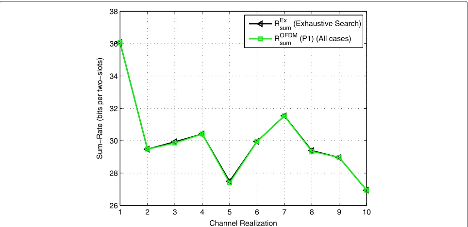
Since the optimization problem (6) is a mixed-integer program problem, we investigate the convergence of ‘Algorithm IP’ by comparing it with one in which the relay operation mode and the decoding order search on each subcarrier is performed in an exhaustive manner, i.e., all possible combinations are considered, and the power allocation is kept as in Section 5.3. Note that, using this exhaustive search algorithm, for the relay operation mode and the decoding orders to be chosen optimally, the search should consider 7K combinations. LetREx
sumdenote
the sum-rate obtained by using the described exhaustive search-based algorithm.
In Figure 10, we compare the maximized sum-rate ROFDMsum achieved by ‘Algorithm IP’ with RExsum achieved by the exhaustive search-based algorithm for K = 4 and ten given channel realizations. Figure 10 shows that ‘Algorithm IP’ has the same performance as the exhaustive based algorithm. Note that the exhaustive search-based algorithm is more largely time and computational resources consuming, especially at a large value ofK. Also, note that ‘Algorithm IP’ is based on coordinate descent method, and it yields increasing sum-rate as the iterations continue until the power vectors{β[k]}Kk=1are saturated,
1 2 3 4 5 6 7 8 9 10
26 28 30 32 34 36 38
Channel Realization
Sum−Rate (bits per two−slots)
RExsum (Exhaustive Search)
ROFDM
sum (P1) (All cases)
Figure 10 ‘Algorithm IP’ vs Exhaustive search. Numerical values areK=4, 10 log(P/N)=20 dB,σ2
and thus, convergence is guaranteed. Finally, we discuss the complexity of ‘Algorithm IP’. The average number of iterations required for ‘Algorithm IP’ to converge is no more than three iterations. We should note that this result is taken over 100 channel realizations and the numerical values of channel coefficients are chosen such thatσar2 = σ2
br=26 dB,σrd2 =20 dB, andσad2 =σbd2 =0 dB. Also, we
useK=128,1=2=10−2, and 10 log(P/N)=20 dB.
We should note that the OFDM scheme has some addi-tional complexities that depend on various parameters and that are beyond the scope of this paper, e.g., the complexity at the receivers due to the operation of suc-cessive decoding. We should also note that if we only consider cases 2 and 5, there is no need of succes-sive decoding at the destination since each transmitted codeword is decoded at the destination in a different time slot. Thus, in general, the complexity of OFDM scheme can be decreased at the expense of lower sum-rate which is still larger than the one obtained using OFDMA scheme.
8 Conclusions
We consider communication over a two-source multiac-cess relay channel in which all the channels are assumed to be frequency selective. In order to handle the frequency selectivity of the channels, we incorporate OFDM trans-mission into the system. We study and analyze the per-formance of a transmission scheme in which the relay is half-duplex and implements a decode-and-forward strat-egy. In contrast to previous works, both sources can transmit their messages using all subcarriers and the relay can decide to help none, only one, or both sources. For this scheme, we derive the achievable sum-rate and study the problem of allocating the powers, selecting the relay operation modes and the decoding orders at the relay and the destination optimally in a way to maximize the obtained sum-rate. We propose an iterative coordinate-descent algorithm that finds a solution that is at least local optimum. We illustrate our results through some numer-ical examples. In particular, our analysis shows that by allowing the sources to possibly transmit on the same subcarrier simultaneously, one can afford a larger sum-rate, i.e., the OFDM-based transmission scheme offers a substantial sum-rate gain over the one that is based on OFDMA.
Appendix 1: Some useful definitions
Appendix 2: Proof of Proposition 1
Recall the seven possible cases that we mentioned in Remark 1, summarized in Table 1. In what follows, because of symmetry, we only analyze the following four cases for the transmission on subcarrierk, 1 ≤ k ≤ K: Case 1) transmission to the destination on subcarrier k utilizes only the direct links, i.e., the relay remains idle on subcarrierk, Case 2)the relay helps only one source on subcarrierk, e.g., sourceBby decoding and forwarding the transmitted symbol xb[k], Case 3) the relay helps both sources simultaneously on subcarrier k, and the codewordxb[k] of sourceBis decoded first at both relay and destination, andCase 4)the relay helps both sources simultaneously on subcarrierk, with the codewordxa[k] of sourceAdecoded first at the relay and the codeword xb[k] of sourceBdecoded first at the destination. The analysis of the remaining three cases (obtained respec-tively from case 2, case 3, and case 4 by swapping the roles of the sources) can be obtained straightforwardly by symmetry. For each of the four cases that will be analyzed, we first describe the decoding procedures at the relay and the destination and then analyze the achievable sum-rate.
Case 1Transmission using only direct links: This sce-nario corresponds to a regular MAC, and the sum-rate that is achievable on subcarrierk, 1≤ k ≤ K, can easily be shown (Theorem 4.4, [28]) to beR1[k] as given by (16)
in Definition 1.
Case 2The relay helps only sourceB:At the end of the first transmission period, the relay gets the output vector yr[k] given by (1). The relay utilizes joint typicality decod-ing to decode the codewordxb[k] transmitted by source
Bon subcarrierk, 1≤k≤K. In doing so, the relay treats the codewordxa[k] transmitted by sourceAas unknown noise or interference. We assume that the codewordxa[k] is considered as normal distributed interference. For large n, the decoding can be done reliably at rate
R(br2)[k]= 1
where the upperscript refers to the case in hand and the lowerscript refers to the channel link. The relay then for-wards the decoded codeword on the same subcarrierkto the destination, during the second transmission period. To this end, the relay sends
˜
The destination, using its output components
(yd[k] ,y˜d[k]), decodes the codewords transmitted by both sources successively. Given that the relay helps only sourceB, it can be shown relatively straightforwardly that,
in this case, decoding the relayed codewordxb[k] first, i.e., before canceling out its contribution and decoding the non-relayed codewordxa[k], results in a sum-rate that is larger than the one that would be achievable if the decod-ing of the codewords at the destination is performed in the reverse order. Thus, the destination first decodes codeword xb[k], cancels its contribution out, and then decodes codeword xa[k]. In order to decode codeword
xb[k], the destination combines the output components
yd[k] andy˜d[k] to their maximum ratio, i.e., using stan-dard MRC. It can be shown that, for largen, the decoding of codewordxb[k] can be decoded reliably at rate
R(bd2)[k]= 1
Next, the destination subtracts out the contribution of xb[k] fromyd[k] and, so, decodes the codewordxa[k] free of interference. It can be shown that, for largen, this can be done reliably at rate
R(ad2)[k]= 1
From the above, it follows that, in this case, the desti-nation can decode reliably the sources’ codewords that are transmitted on subcarrierk, 1≤ k ≤ K, as long asn is large and these codewords are sent at a sum-rate that is no larger than the sum of R(ad2)[k] and the minimum amongR(br2)[k] andRbd(2)[k], i.e.,R2[k] as given by (17) in
Definition 1.
Case 3The relay helps both sources, and the decoding orders at the relay and the destination are identical:In this case, we assume that the relay helps both sources and that the relay and the destination first decode codewordxb[k], cancel out its contribution, and then decode codeword xa[k].
Consider first the decoding operations at the relay. At the end of the first transmission period, the relay gets the output vectoryr[k] and decodes the codewordxb[k] exactly as in case 2. Thus, for largen, the relay can get the correctxb[k] at rateR(br3)[k]=R
(2)
br[k] as given by (23).
The relay then subtracts out the contribution of xb[k] fromyr[k] and then decodes codewordxa[k], again using a joint typicality decoding. Similarly, for largen, this can be done reliably at rate
R(ar3)[k]= 1
power among re-transmitting codeword xa[k] and re-transmitting codeword xb[k], on the same subcarrierk, using superposition coding. That is, the relay sends
˜
The destination, using its output components (yd[k] , ˜
yd[k]), decodes the codewords transmitted by both sources successively, in the same order this is per-formed at the relay. More precisely, the destination first decodes codewordxb[k], cancels its contribution out, and then decodes codewordxa[k]. In order to decode code-wordxb[k], the destination combines the output compo-nentsyd[k] andy˜d[k] to their maximum ratio. Through straightforward algebra, which we omit for brevity, it can be shown that, for large n, the destination can get the correctxb[k] at rate
R(bd3)[k]= 1
2log2(1+snrb[k]), (29)
where snrb[k] is given in Definition 2. Next, the desti-nation subtracts out the contribution of codewordxb[k] from (yd[k] ,y˜d[k]) and combines the resulting equiva-lent output components using MRC to decode codeword xa[k]. Again, through straightforward algebra, which we omit for brevity, it can be shown that, for large n, the destination can get the correctxa[k] at rate
R(ad3)[k]=1
From the above, it follows that, in this case, the desti-nation can decode reliably the sources’ codewords that are transmitted on subcarrierk, 1≤ k ≤ K, as long asn is large and these codewords are sent at a sum-rate that is no larger than the sum of the minimum amongR(ar3)[k]
andR(ad3)[k] and the minimum amongRbr(3)[k] andR(bd3)[k], i.e.,R3[k] as given by (18) in Definition 1.
Case 4 The relay helps both sources, and the decoding orders at the relay and the destination are different:In this case, we assume that the relay helps both sources and that the relay and the destination decode the sources’ code-words in different orders. In particular, in what follows, we analyze the case in which the decoding order at the relay is such that codeword xa[k] is decoded first, and the decoding at the destination is maintained as in case 3 above.
Consider first the decoding operations at the relay. At the end of the first transmission period, the relay gets the output vector yr[k] given by (1). Proceeding along the lines in the analysis of case 3 above, but the roles of
codewordsxa[k] andxb[k] swapped, it can be shown that,
The decoding at the destination is exactly as in case 3. Thus, for largen, the destination can first get the correct xb[k] at rateR(bd4)[k]= R(bd3)[k] as given by (29) and then subtract its contribution out and get the correct codeword xa[k] at rateR(ad4)[k]=R(ad3)[k] as given by (30).
From the above, it follows that, in this case, the destina-tion can decode reliably the sources’ codewords that are transmitted on subcarrier k, 1 ≤ k ≤ K, as long as nis large and these codewords are sent at a sum-rate that is no larger than the sum of the minimum amongR(ar4)[k] and R(ad4)[k] and the minimum amongRbr(4)[k] andR(bd4)[k], i.e., R4[k] as given by (19) in Definition 1.
This completes the analysis of cases 1 to 4. The analy-sis of case 5, case 6, and case 7 in Table 1 can be obtained straightforwardly respectively from the analysis of case 2, case 3, and case 4, by swapping the roles of sourceAand source B. This leads to the associated sum-ratesR5[k], R6[k], andR7[k] as given in Definition 1.
Summary: For given channel states {har[k] ,hbr[k] , had[k] ,hbd[k] ,hrd[k]}Kk=1 and power policy {β[k]}Kk=1,
the sum-rates ofRl[k] bits per second, 1 ≤ l ≤ 7, are achievable on subcarrierk, 1≤k≤K, using the OFDM-based transmission that we described. Thus, the sum-rate R[k]= max1≤l≤7Rl[k] on subcarrier k, i.e., the maxi-mum among the seven sum-rates{Rl[k]}7l=1, is obtained by selecting for subcarrierkthe coding scheme that offers the larger per-subcarrier sum-rate among those of the aforementioned seven cases. Next, since OFDM trans-forms the channel into a set ofK parallelsubchannels, the total sum-rate that is offered through the transmission, over all subchannels, is obtained by simply summing over all subchannels the individual achievable per-subcarrier sum-rates [28].
Competing interests
The authors declare that they have no competing interests.
Acknowledgements
The material in this paper has been presented in part at the International Symposium on Communications, Control and Signal Processing, Limassol, Cyprus, March 2010.
Author details
1ICTEAM, Université catholique de Louvain, Place du Levant, 2, 1348
Louvain-la-Neuve, Belgium.2Laboratoire d’Informatique Gaspard Monge,
Université Paris-Est, Marne la Vallée Cedex 2, 77454, France.3Mathematical
and Algorithmic Sciences Lab., France Research Center, Huawei Technologies, Paris, France.
Received: 17 October 2014 Accepted: 15 April 2015
References
1. P Gupta, PR Kumar, The capacity of wireless networks. IEEE Trans. Inf. Theory.46, 388–404 (2000)
2. NJ Laneman, DN Tse, GW Wornell, Cooperative diversity in wireless networks: efficient protocols and outage behavior. IEEE Trans. Inf. Theory. 50, 3062–3080 (2004)
3. A Sendonaris, E Erkip, B Aazhang, inIEEE International Symposium on Information Theory. Increasing uplink capacity via user cooperation diversity (IEEE press Piscataway, NJ, 1998), p. 156
4. G Kramer, M Gastpar, P Gupta, Cooperative strategies and capacity theorems for relay networks. IEEE Trans. Inf. Theory.51, 3037–3063 (2005) 5. A Host-Madsen, J Zhang, Capacity bounds and pair allocation for wireless
relay channels. IEEE Trans. Inf. Theory.51, 2020–2040 (2005) 6. L Sankaranarayanan, G Kramer, NB Mandayam, inProc. First IEEE
Conference on Sensor and Ad Hoc Communications and Networks. Hierarchical sensor networks: capacity bounds and cooperative strategies using the multiple-access relay channel model (IEEE press Piscataway, NJ, 2004), pp. 191–199
7. L Sankar, Y Liang, VH Poor, NB Mandayam, inIEEE International Symposium on Information Theory. Opportunistic communications in an orthogonal multiaccess relay channel (IEEE press Piscataway, NJ, 2007), pp. 1261–1265 8. M El-Soussi, A Zaidi, J Louveaux, L Vandendorpe, inInternational
Symposium on Communications, Control and Signal Processing (ISCCSP). Sum-rate optimized power allocation for the OFDM multiple access relay channel (IEEE press Piscataway, NJ, 2010), pp. 1–6
9. M El-Soussi, A Zaidi, L Vandendorpe, Compute-and-forward on a multiaccess relay channel: coding and symmetric-rate optimization. IEEE Trans. Wireless Commun.13, 1932–1947 (2014)
10. S Schedler, V Kuehn, Resource allocation for the multiple-access relay channels and OFDMA. EURASIP J. Adv. Signal Process.120, 1–20 (2013) 11. L Vandendorpe, J Louveaux, O Oguz, A Zaidi, Rate-optimized power
allocation for DF-relayed OFDM transmission under sum and individual power constraints. EURASIP J. Wireless Commun. Netw.814278, 1–11 (2009)
12. T Wang, L Vandendorpe, Sum rate maximized resource allocation in multiple DF relays aided OFDM transmission. IEEE J. Sel. Areas Commun. 29, 1559–1571 (2011)
13. T Wang, L Vandendorpe, WSR maximized resource allocation in multiple DF relays aided OFDMA downlink transmission. IEEE Trans. Sig. Proc.59, 3964–3976 (2011)
14. K Bakanoglu, S Tomasin, E Erkip, Resource allocation for the parallel relay channel with multiple relays. IEEE Trans. Wireless Commun.10, 792–802 (2011)
15. K Jitvanichphaibool, R Zhang, YC Liang, Optimal resource allocation for two-way relay-assisted OFDMA. IEEE Trans. Vehicul. Tech.58, 3311–3321 (2009)
16. HN Vu, HY Kong, Joint subcarrier matching and power allocation in OFDM two-way relay systems. J Commun Netw.14, 257–266 (2012) 17. M Kaneko, P Popovski, inIEEE Int. Conf. Commun. Radio resource allocation
algorithm for relay-aided cellular OFDMA system (IEEE press Piscataway, NJ, 2007), pp. 4831–4836
18. Y Cui, VKN Lau, R Wang, Distributive subband allocation, power and rate control for relay-assisted OFDMA cellular system with imperfect system state knowledge. IEEE Trans. Wireless Commun.8, 5096–5102 (2009)
19. T Ng, W Yu, Joint optimization of relay strategies and resource allocations in cooperative cellular networks. IEEE J. Sel. Areas Commun.25, 328–339 (2007)
20. G Li, H Liu, in38th Annu. Asilomar Conf. Signals, Syst. Comput. On the capacity of the broadband relay networks (IEEE press Piscataway, NJ, 2004), pp. 1318–1322
21. G Li, H Liu, Resource allocation for OFDMA relay networks with fairness constraints. IEEE J. Sel. Areas on Commun.24, 2061–2069 (2006) 22. W Mesbah, TN Davidson, Power and resource allocation for orthogonal
multiple access relay systems. EURASIP J. Adv. Signal Process.476125, 1–15 (2008)
23. J Joung, S Sun, Power efficient resource allocation for downlink OFDMA relay cellular networks. IEEE Trans. Signal Process.60, 2447–2459 (2012) 24. W Dang, M Tao, H Mu, J Huang, Subcarrier-pair based resource allocation
for cooperative multi-relay OFDM systems. IEEE Trans. Wireless Commun. 9, 1640–1649 (2010)
25. M Chiang,Geometric programming for communication systems. (Foundation and Trends in Commun. Inf. Theory, Massachusetts, 2005), pp. 1–156
26. LA Wolsey,Integer Programming. (Wiley, New York, 1998), pp. 1–264 27. M Chiang, CW Tan, DP Palomar, D O’Neill, D Julian, Power control by
geometric programming. IEEE Trans. Wireless Commun.6, 2640–2651 (2007)
28. AE Gamal, Y-H Kim,Network Information Theory. (Cambridge University Press, New York, 2012), pp. 1–685
Submit your manuscript to a
journal and benefi t from:
7Convenient online submission 7Rigorous peer review
7Immediate publication on acceptance 7Open access: articles freely available online 7High visibility within the fi eld
7Retaining the copyright to your article