R E S E A R C H
Open Access
Visible light communication using TDMA
optical beamforming
Sung-Man Kim
1*, Myeong-Woon Baek
1and Seung Hoon Nahm
2Abstract
Optical beamforming is a technique to focus light-emitting diode (LED) light on a desired target and has been used to improve the performance of visible light communications (VLC). In this article, we propose and demonstrate a VLC technology based on time-division multiple access (TDMA) optical beamforming to accommodate multiple target devices. It focuses LED light on each different target device in each different time slot. Our results show that the proposed technique can accommodate multiple target devices and also gives the benefit of optical beamforming (5~10 dB gain) to each target device. Our results also show that the transmission distance increases from 110 to 200 cm with the TDMA optical beamforming.
Keywords:Visible light communication, Optical beamforming, LED, Time-division multiple access
1 Introduction
In recent years, light-emitting diodes (LEDs) have emerged as eco-friendly replacements for incandescent light bulbs and fluorescent lamps because of high electric-to-optic conversion efficiency, long lifetime, small size, etc. LEDs also have an interesting feature that the light output can be modulated with high-frequency signals. Using this phenomenon, LED can be used for optical wireless communications, which is usually called visible light communications (VLC) [1–7]. VLC is emerging as a promising alternative for future indoor wireless com-munication because of its unregulated huge bandwidth (~400 THz), low power consumption, no electromag-netic interference (EMI) generation, etc.
Currently, the performance of VLC cannot surpass the current WiFi technology. Therefore, performance improve-ment of VLC is one of the key issues for commercialization. To improve the performance of VLC, a lot of techniques have been proposed including electrical and optical domain approaches. Electrical domain approaches in-clude equalization [8], quadrature amplitude modula-tion (QAM) [9], and orthogonal frequency division multiplexing (OFDM) [10]. Optical domain approaches in-clude blue filtering [8], multiple-input multiple-output
(MIMO) [11], wavelength-division multiplexing (WDM) [12, 13], and polarization division multiplexing (PDM) [14].
Recently, one of the optical domain approaches called
“optical beamforming” technique has been proposed to enhance the performance of VLC. Optical beamforming is a technique to focus LED light on a desired target so that it can enhance the signal-to-noise ratio (SNR) of the received VLC signal [15, 16]. Since it does not depend on electrical signal formats, it can be widely used in various VLC schemes.
However, the previous demonstration of the VLC using optical beamforming could communicate with only a single target. In the real-life applications, multiple user devices should be accommodated. Therefore, in this paper, we propose and demonstrate a VLC technology using time-division multiple access (TDMA) optical beamforming to accommodate multiple user devices, which focuses LED light on each different target device in each different time slot.
2 VLC using TDMA optical beamforming
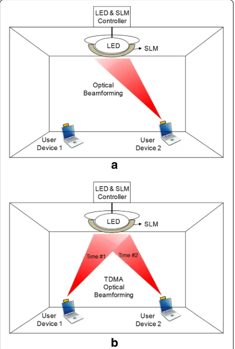
Figure 1 shows the structure and concept of the VLC systems based on ordinary optical beamforming (Fig. 1a) and TDMA optical beamforming (Fig. 1b). Both VLC systems consist of a LED light, a spatial light modulator (SLM), a LED/SLM controller, and user devices. The LED light is covered by a SLM to control the LED light beam. A SLM is a transparent or reflective optical device * Correspondence:[email protected]
1Department of Electronic Engineering, Kyungsung University, Nam-Gu,
Busan 48434, Republic of Korea
Full list of author information is available at the end of the article
© The Author(s). 2017Open AccessThis article is distributed under the terms of the Creative Commons Attribution 4.0 International License (http://creativecommons.org/licenses/by/4.0/), which permits unrestricted use, distribution, and reproduction in any medium, provided you give appropriate credit to the original author(s) and the source, provide a link to the Creative Commons license, and indicate if changes were made.
Kimet al. EURASIP Journal on Wireless Communications and Networking (2017) 2017:56
which can modulate the phase or amplitude of light on each pixel, so can be operated as a dynamic diffractive element controlled by electrical signals [17]. The elec-trical signal is modulated by the LED and the optical beamforming is controlled by the SLM.
In Fig. 1, a scenario of two user devices is assumed. As shown in Fig. 1a, the VLC system based on ordin-ary optical beamforming can accommodate only a single target. However, in the real-life applications, multiple user devices should be accommodated. Therefore, we propose a VLC technique based on TDMA optical beamforming, as shown in Fig. 1b, which focuses LED light on each user device in each time slot. For example, the LED light is focused on user device 1 at a time slot 1 and then it is focused on user device 2 at a time slot 2. The SLM focuses the LED light on each user device according to the location and allotted time slot of each device. The location of user devices can be detected by using a location-detecting algorithm based on direction code, which has been proposed previously [15].
3 Experimental setup
Figure 2 shows the block diagram of the experimental setup for the proposed VLC using TDMA optical beam-forming. Figure 3 shows the picture of the experimental setup. In the experimental setup, a LED is modulated by a pseudo-random binary sequence (PRBS), non return-Fig. 1Concepts and structures of the VLC systems based ona
ordinary optical beamforming andbTDMA optical beamforming
Fig. 2Block diagram of the experimental setup for VLC using TDMA optical beamforming
Fig. 3Picture of the experimental setup
to-zero (NRZ) signal. The modulated LED light is passed through a beam expander in order to control the beam size and form it into a parallel ray. The beam expander can be omitted if the optical design is optimized. After the beam expander, the light goes into a spatial light modulator (SLM), which has 800 × 600 translucent liquid crystal pixels with a pixel pitch of 32 × 32μm. The size of the active area in the SLM is 26.6 × 20.0 mm. The SLM is an optical device that can modulate optical phase on each pixel in 256 levels (8 control bits), so it can op-erate as a dynamic diffractive element controlled by electrical signals.
A control computer sends a Fresnel lens function to the SLM according the information of the TDMA time slot and location of the target devices. This signal modu-lates the phase of SLM pixels and the SLM functions like a dynamic lens. After passing through the SLM, the light is beamformed and focused on the optical re-ceivers. OSRAM SFH-213 photodiodes are used for the optical receivers. Either amplifiers or filters are not used in the receiver site.
The focal length of the optical beamforming is de-termined by the radius of circles in a Fresnel lens function and the wavelength of the light, which is given by
L¼R2
1=λ; ð1Þ
where L is the focal length, R1 is the radius of the first circle in the Fresnel lens function, andλis the wavelength of the light. The Fresnel lens function is controlled by a control computer according to the information of the time slot and the location of the target devices. In the experi-ment, two different target devices are considered. In time slot 1 and 2, the Fresnel lens function is controlled to focus the LED light on target 1 (ch.1) and target 2 (ch.2), respectively. The Fresnel lens function for each time slot is shown as a gray display in Fig. 4, which shows the level of phase transition. The separation distance between the two circle centers in time slot 1 and 2 is 14 mm in the SLM. Detailed system parameters of the experiment are summarized in Table 1.
4 Results and discussion
Figure 5 shows the experimental results of the TDMA optical beamforming on the screen in time slot 1 and 2
Table 1System parameters of the experiment
System parameters Values
Pixel size of SLM 32 × 32μm
Active area of SLM 26.6 × 20.0 mm
Display resolution of SLM 800 × 600 pixels
Gray level of SLM 256 (8 bits)
# of TDMA receivers 2
Separation distance of channels in SLM 14 mm
Fig. 5Experimental results of the TDMA optical beamforming on the screen inatime slot 1 andbtime slot 2
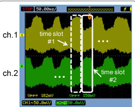
Fig. 6Measured VLC signals in ch.1 and ch.2 with a large time scale. The result in thedashed lineis when the light is focused on ch.1 and the result in thesolid line is when the light is focused on ch.2
Fig. 7Measured VLC signals in ch.1 and ch.2 with a small time scale inatime slot 1 andbtime slot 2
at a transmission distance of 90 cm. Because the LED light after the beam expander is a parallel ray, the optical foot print size is similar to the SLM active area. In time slot 1 and 2, the light is focused on ch.1 and ch.2, re-spectively. The bright dots in Fig. 3 are the focused points by the TDMA optical beamforming. The faint crisscross pattern is due to the diffraction of two-dimensional pixel matrix of the SLM. The SLM model used in the experiment cannot operate as a perfect phase modulator, so some unmodulated light is still seen on the screen even after the TDMA optical beamforming. It should be noted that the modulation depth of the phase modulation in the SLM can be adjusted, so the
brightness of the focused points can be controlled. The modulation depth of the SLM can be controlled ac-cording to the requirement of system or a user. This function may be important when the LED light is also used for illumination.
Figure 6 shows the received signals in ch.1 and ch.2 with a large time scale. When the LED light is focused on ch.1, the signal amplitude of ch.1 increases from 116 to 208 mV (5.1 dB gain). The duration time of each time slot is set to about 50 ms because it is the maximum control rate of the SLM. When it is focused on ch.2, the signal amplitude of ch.2 increases from 80 to 148 mV (5.3 dB gain). The illumination increases from 60 to Fig. 8Amplitudes of the received VLC signal as a function of transmission distance before and after the TDMA optical beamforming (TDMA OB)
100 mW/m2 for both channels. The results show that each channel can enjoy the benefit of optical beamform-ing durbeamform-ing its time slot. The received VLC signals with a small-time scale are shown in Fig. 7. In Fig. 7, it is shown that the VLC operation is successful even while optical beamforming is operating.
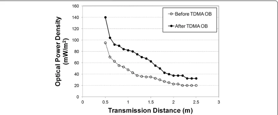
Figure 8 shows the amplitudes of the received VLC signals as a function of transmission distance before and after the TDMA optical beamforming. The results show that amplitudes of the received VLC signals are improved by 5~10 dB in the transmission distance of 60~140 cm thanks to the TDMA optical beamform-ing. The maximum transmission distance increases from 1.4 to 2.4 m thanks to the TDMA optical beam-forming. Figure 9 shows the received optical power density at the receivers as a function of transmission distance before and after the TDMA optical beam-forming. In the experimental results, the optical power density increases by 2~4 dB in the transmis-sion distance of 80~250 cm thanks to the TDMA op-tical beamforming.
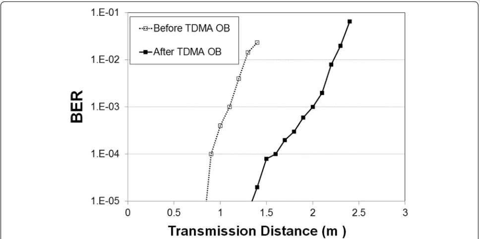
Figure 10 shows the bit error rate (BER) performance of the VLC before and after the TDMA optical beam-forming as a function of transmission distance. If we define a BER of <10−3as a criterion for successful trans-mission, the transmission distance increases from 110 to 200 cm with the TDMA optical beamforming. It should be noted that a SLM has a little optical loss even though the gain of the TDMA optical beamforming is higher than the optical loss.
5 Conclusions
We have proposed and demonstrated a VLC using TDMA optical beamforming to accommodate multiple users in the VLC using optical beamforming. TDMA op-tical beamforming is a technique to focus LED light on each different target device in each time slot. Our results have shown that each user device can enjoy the benefit of the optical beamforming during its time slot with the TDMA optical beamforming. The VLC signal amplitude of each channel increases by 5~10 dB, the optical power density of the VLC signal increases by 2~4 dB, and the transmission distance increases from 110 to 200 cm with the TDMA optical beamforming. Since the proposed technique can increase the performance of VLC effi-ciently and does not depend on the electrical modulation formats, it can be widely used in various applications.
Acknowledgements
This research was supported by the Basic Science Research Program through the National Research Foundation of Korea (NRF) funded by the Ministry of Science, ICT and Future Planning (No. 2012M3C1A1048865 and NRF-2015R1C1A1A01052543).
Funding
This research was supported by the Basic Science Research Program through the National Research Foundation of Korea (NRF) funded by the Ministry of Science, ICT and Future Planning (No. 2012M3C1A1048865 and NRF-2015R1C1A1A01052543).
Authors’contributions
S-MK is the main writer of this paper. He proposed the main idea, conducted the experiment, and analyzed it. M-WB conducted the experiment with S-MK. SHN assisted the experiment. All authors read and approved the final manuscript.
Fig. 10BER performance before and after the TDMA optical beamforming (TDMA OB)
Competing interests
The authors declare that they have no competing interests.
Publisher’s Note
Springer Nature remains neutral with regard to jurisdictional claims in published maps and institutional affiliations.
Author details
1Department of Electronic Engineering, Kyungsung University, Nam-Gu,
Busan 48434, Republic of Korea.2Korea Research Institute of Standards and Science (KRISS), Daejeon 34113, Republic of Korea.
Received: 29 May 2015 Accepted: 14 March 2017
References
1. S Rajagopal, RD Roberts, S-K Lim, IEEE 802.15.7 visible light communication: modulation schemes and dimming support. IEEE Commun. Mag.
50, 72–82 (2012)
2. CW Chow, CH Yeh, YF Liu, PY Huang, Y Liu, Adaptive scheme for maintaining the performance of the in-home white-LED visible light wireless communications using OFDM. Opt. Commun.292, 49–52 (2013) 3. P Das, B-Y Kim, Y Park, K-D Kim, Color-independent VLC based on a color space without sending target color information. Opt Commun
286, 69–73 (2013)
4. SJ Lee, JK Kwon, S-Y Jung, Y-H Kwon, Evaluation of visible light communication channel delay profiles for automotive applications. EURASIP J. Wirel Commun Netw2012, 370 (2012)
5. T Komine, M Nakagawa, Fundamental analysis for visible-light communication system using LED lights. IEEE Trans. Consum. Electron.
50, 100–107 (2003)
6. SP Rodríguez, RP Jiménez, BR Mendoza, FJL Hernández, AJA Alfonso, Simulation of impulse response for indoor visible light communications using 3D CAD models. EURASIP J. Wirel. Commun. Netw.7, 2013 (2013) 7. Y Wu, A Yang, L Feng, Y Sun, Efficient transmission based on RGB LED lamp
for indoor visible light communication. Chin. Opt. Lett.11, 030601 (2013) 8. H Le Minh, D O’Brien, G Faulkner, L Zeng, K Lee, D Jung, Y Oh, ET
Won, 100-Mb/s NRZ visible light communications using a postequalized white LED. IEEE Photon. Technol. Lett.21, 1063–1065 (2009)
9. Y Wang, X Huang, J Zhang, Y Wang, N Chi, Enhanced performance of visible light communication employing 512-QAM N-SC-FDE and DD-LMS. Opt. Express22, 15328–15334 (2014)
10. H Elgala, R Mesleh, H Haas, Indoor broadcasting via white LEDs and OFDM. IEEE Trans. Consum. Electron.55, 1127–1134 (2009)
11. S-M Kim, J-B Jeon, Experimental demonstration of 4 × 4 MIMO wireless visible light communication using a commercial CCD image sensor. J. Inf. Commun. Converg. Eng.10, 220–224 (2012)
12. Y Wang, C Nan, A high-speed bi-directional visible light communication system based on RGB-LED. China Commun.11, 40–44 (2014) 13. PP Han, A Sewaiwar, SV Tiwari, Y-H Chung, Color clustered
multiple-input multiple-output visible light communication. J. Opt. Soc. Korea
19, 74–79 (2015)
14. CH Yeh, YL Liu, CW Chow,Demonstration of 76 Mbit/s real-time phosphor-LED visible light wireless system(Proc. Optoelectronics and Communication Conference (OECC), Melbourne, 2014), pp. 757–759
15. S-M Kim, S-M Kim, Wireless visible light communication technology using optical beamforming. Opt. Eng.52, 106101 (2013)
16. S-M Kim, H-J Lee, Visible light communication based on space-division multiple access optical beamforming. Chinese Opt. Lett.12, 120601 (2014) 17. J Remenyi, P Varhegyi, L Domjan, P Koppa, E Lorincz, Amplitude, phase, and
hybrid ternary modulation modes of a twisted-nematic liquid-crystal display at ~400 nm. Appl. Opt.42, 3428–3434 (2003)
Submit your manuscript to a
journal and benefi t from:
7 Convenient online submission 7Rigorous peer review
7 Immediate publication on acceptance 7Open access: articles freely available online 7 High visibility within the fi eld
7Retaining the copyright to your article