Volume 2011, Article ID 376394,13pages doi:10.1155/2011/376394
Research Article
Performance-Driven Symbol Mapping for Downlink and
Point-to-Point MIMO Systems
C. Masouros
1and E. Alsusa
21School of Electrical Engineering, Electronics & Computer Science, Queen’s University Belfast, Belfast BT3 9DT, UK 2School of Electrical & Electronic Engineering, University of Manchester, P.O. Box 88, Manchester M601QD, UK
Correspondence should be addressed to C. Masouros,[email protected]
Received 25 October 2010; Revised 10 January 2011; Accepted 18 February 2011
Academic Editor: Rodrigo C. De Lamare
Copyright © 2011 C. Masouros and E. Alsusa. This is an open access article distributed under the Creative Commons Attribution License, which permits unrestricted use, distribution, and reproduction in any medium, provided the original work is properly cited.
An adaptive symbol mapping scheme is proposed for single-user point-to-point and multiuser downlink multiple-input multiple output (MIMO) systems aiming at the minimization of the overall system bit error rate. The proposed scheme introduces a disorder to the symbols to be transmitted within a MIMO subframe by means of dynamic mapping, with the objective to optimise the interference between them and enhance the received symbols’ power. This is done by either changing the allocation order of the symbols to the antennas or by applying a scrambling process that alters the symbols sign. This procedure is targeted to optimizing, rather than strictly minimizing the interference between the symbols such that constructive instantaneous interference is utilized in enhancing the decision variables at the receiver on a symbol-by-symbol basis so that detection is made more reliable. In this way, the overall system performance is improved without the need to raise the transmitted power. The proposed scheme can be used in conjunction with various conventional MIMO precoding and detection techniques. The presented results show that for a given transmit power budget this scheme provides significant benefits to the corresponding conventional system’s error rate performance.
1. Introduction
The recent advances in multiple-input multiple-output (MIMO) processing [1] are making the application of multiantenna transmitters and receivers increasingly popular in modern wireless communications due to the enhanced capacity and space diversity they offer. MIMO schemes have recently been incorporated in communication standards such as WiMAX and 3GPP-LTE to satisfy the growing demand for higher data rates and quality of service for multimedia applications. Despite the increased information capacity offered by the MIMO channel, the spatial correla-tion of the multiple subchannels introduces an addicorrela-tional source of interference which corrupts the data symbols and in effect degrades the achievable error rate performance of such systems. In the MIMO uplink, space diversity detection techniques [2–5] can counteract this impediment to a satisfactory extent. In [2, 3], the sphere decoder is presented for an arbitrary lattice code and a lattice code
throughput delivered are limited and do not improve by increasing the number of antennas, as demonstrated in [7]. The solution proposed in [7], which is a minimum mean square error (MMSE) form of channel inversion, provides some performance and capacity gains with respect to the conventional CI, without a considerable complexity increase. Nevertheless, the transmission rates offered by both these schemes are far from reaching the theoretical channel capacity. Dirty paper coding (DPC) techniques as, for example, in [8–11] based on the initial information theoretical analysis in [12], can further increase transmission rates and achieve significant capacity benefits. However, the majority of the DPC methods developed so far are impractical in many scenarios as they require sophisticated signal processing at the transmitter with complexity similar to the one of sphere decoding. A promising alternative is the joint transmit-receive beamforming scheme as presented in [13] amongst others in the literature. Despite being less complex than DPC, the most robust beamforming schemes require iterative communication between the transmitter and receiver for the optimization of the joint processing and the system configuration. This needs to be done every time the channel characteristics change and hence, in fast fading environments introduces considerable latency to the MIMO downlink system. Owing to their favourable performance-to-complexity tradeoffamongst the techniques mentioned above, this paper focuses on the application of the proposed scheme to the more practical V-BLAST detection and MMSE precoding.
Complementary to the aforementioned signal enhance-ment processing MIMO schemes, a number of resource allocation schemes [14–19] have emerged for MIMO com-munications mainly involving antenna selection [14–16] and power allocation [17,18] for multielement transceivers as well as frequency (subcarrier) allocation [19] for MIMO-orthogonal frequency division multiplexing (OFDM) com-munications. All the relevant resource allocation methods focus on the reduction of interference between the spatial streams of the MIMO channel. This clearly differentiates them to the proposed scheme where the aim is not strictly to minimise the correlation of the spatial streams but rather to optimise it and accommodate for constructive interchannel interference (ICI). Moreover, resource allocation schemes such as antenna selection can be used in addition to the proposed technique to further improve the performance. The focus of this paper, however, is on signal enhancement schemes and for reasons of coherence, antenna selection and power allocation are not considered here.
In more detail, the proposed scheme which parallels the ones in [20, 21] proposed for code division multiple access (CDMA) is based on the fact that ICI is separated into constructive and destructive as discussed in detail in [22]. The characterisation of the instantaneous ICI depends on the channel characteristics and the correlation between the spatial streams, and, equally importantly, on the instantaneous values of the transmitted symbols. By perturbing the data symbols to be transmitted by means of reordering or scrambling, the proposed scheme influences the ICI between the MIMO subchannels. It then chooses
a symbol mapping such that the interference is optimised and the decision variables at the receiver are maximised. Subsequently, conventional precoding or detection can be applied with enhanced performance due to the optimisation of interference achieved by the proposed symbol mapping.
It is clear that the proposed symbol mapping scheme can be combined with various conventional MIMO detection (linear detection, V-BLAST, sphere decoding, etc.) and precoding schemes (linear precoding, dirty paper coding etc.) to improve the respective performance. For reasons of simplicity and to maintain the focus of the present paper, as mentioned above, only two of the most practical and popular MIMO techniques are considered here, MMSE precoding and V-BLAST detection.
It should be noted that the proposed data allocation method entails the transmission of control signalling (CS) to inform the receiver about the mapping process used so as to attain the correct initial order or appropriately descramble the received data after detection. It will be shown that the CS increases logarithmically with the number of candidate mapping patterns and for this reason the number of possible reordered or scrambled versions of the data to select from should be limited. In the simulations presented here this number is limited to values such that the overhead imposed by the CS transmission is restricted to less than 6% of the transmitted information.
2. System Model and Conventional
MIMO Processing
This paper considers transmission in a MIMO system with a limited number of N transmit (Tx) and M receive (Rx) antennas over a frequency flat fading channel. As commonly suggested in the literature, the received signals of all antennas for theith symbol period can be combined in anM×1 vector
r(i)=H·x(i)+w(i). (1)
Herer(i)=[r(i)
1 ,r(2i),. . .,rM(i)]TandHis theM×Nmatrix that contains the complex frequency flat channel coefficients with the (m,n)th elementhm,nbeing the zero-mean unit-variance channel tap between thenth transmit antenna and themth receive antenna. Also,x(i)=[x(i)
1 ,x(2i),. . .,xN(i)]Tis theN×1 vector with the symbols transmitted by theN Tx antennas and w(i) = [w(i)
1 ,w2(i),. . .,w(Mi)]T is the M×1 vector of the additive white Gaussian noise (AWGN) components at the MRx antennas. For reasons of completeness and to intro-duce the notation used in this paper, the following briefly presents the conventional MMSE precoding and V-BLAST detection schemes. A modification to the conventional V-BLAST is also introduced to make it more compatible with the proposed method.
2.1. Linear Minimum Mean Square Error (MMSE) Precoding.
the receiver is maximized. The transmitted symbol vector is the MMSE-like pseudoinverse of the channel matrix andH∗ denotes the Hermitian transpose ofH. f is a scaling factor that ensures thatE{x(i)2} =1 and is given as
f =
1
T2 (3)
which derives average normalization of the transmitted power. It can be seen that in this case the channel is not entirely orthogonalized and a certain amount of interference remains. The received symbol vector is given as
r(i)= f ·R·b(i)+w(i), (4)
where
R=H·T=H·H∗·(H·H∗+a·I)−1 (5)
is the equivalent crosscorrelation matrix of the symbols as seen at the receiver. The estimated symbols are retrieved by directly quantizing the received signal
b(i)=Qr(i), (6)
where Q(·) represents the quantization operation. It is shown in [9] that the value ofathat maximizes the received SINR is a = Mσ2, where σ2 is the noise variance at the receiver. It is demonstrated that this precoding outperforms full channel inversion in symmetric MIMO systems where N=Msuch as the ones investigated here.
2.2. Vertical Bell Laboratories Layered Space Time (V-BLAST)
Detector and Proposed Modification. The V-BLAST detector
proposed in [5] involves iterative detection and cancellation of the interfering symbols at each antenna in order to attain an interference-free detection of the desired signal. No precoding is applied at the transmitter (T = I) and hencex(i)=b(i)as the cancellation process is applied on the received signalr(i)of (1). The function of the scheme is well explained in [5] and for reasons of completeness we present the compact recursive procedure of the technique:
Initialisation:
Here [Y]u denotes theuth column if Y is a matrix or the uth element ifYis a vector,YT denotes the transpose ofY, km denotes the index of the selected symbol to be detected and cancelled at the mth recursion and bkm is the kmth estimated symbol. In (7e), the estimated interference from symbolbkm is regenerated using channel state information (CSI) and canceled out from the received signal. In (7f) the rows k1 to km are zeroed in the channel matrix to provide Hkm on which the new equalization matrix Gm+1 is based. It is important to stress that in the recursive detection-reconstruction-cancellation part, themth symbol to be cancelled is selected as the one that corresponds to the row inGm with the minimum norm. This is done so that the increase in noise power due to multiplication with gkmat each recursion is minimized. However, for the pairing of V-BLAST with the proposed scheme the simulations showed that a criterion based on the one proposed for successive interference cancellation (SIC) in code division multiple access (CDMA) systems in [23] is more appropriate. Therefore in the simulations shown below the received signal is multiplied with the entire equalization matrix at each recursion and the symbol with the highest norm (most reliable for detection) is selected for cancellation at each iteration of the algorithm. Hence, while the conventional V-BLAST is simulated in the graphs below using the procedure in (7a)–(7f) for the combined V-BLAST and symbol map-ping the BLAST algorithm is modified to:
As regards the equalized symbols to be detected in (8b) assuming perfect cancellation the expression can be trans-formed using (8f) to
whereRm is the crosscorrelation of the remaining symbols at the mth cancellation iteration, and η(i)
m is the noise component after channel equalization. It can be proven that the noise component η(i)
m has on average increased power compared to w(mi) after multiplication with the nonunitary channel equalization matrix.
3. Proposed Optimized Symbol Allocation (SA)
In both (4) and (9) it can be seen that when the transmitted data symbols are reordered they are paired with different crosscorrelation elements in the crosscorrelation matrix and the interference between them changes so that the values of the resulting decision variables are different. Hence, instead of transmitting the symbolsb(i)as they appear at the output of the information source, it would be beneficial to the communication system to reorder the symbols in a way that the decision variables resulting from (4) and (9) are enhanced. This serves as the motivation behind the proposed SA scheme, the flow diagram of which is illustrated in Figure 1. The proposed algorithm involves the following steps.
(1) From an initial reference symbol-to-antenna allo-cation pattern a limited number of D candidate allocation patterns are formed offline, known both to the transmitter and receiver. The value ofDshould be limited, so that the CS bits (needed to convey which of theDcandidates was used to the receiver) do not impose an overwhelming transmission overhead.
Transmitter
(2) For each candidate the expected decision variables are preestimated according to the signal enhancement mechanism employed (precoding or detection). For the MMSE and V-BLAST techniques considered here the preestimated symbols are given by (6) and (8d), respectively using the channel estimates. The vectors containing the decision variables for each candidate allocation are stacked to form the M ×D matrix
b(i). The pth column of the matrix, denoted as b(i) p for simplicity, contains the preestimated decision variables for the pth candidate symbol allocation withp∈ {1, 2,. . . D}.
(3) A symbol allocationpoptis selected based on an error rate minimization criterion that will be shown in the following.
(4) The transmitter subsequently allocates the symbols to the antennas based on the selected allocation and, if applicable, precodes the data using some form of conventional precoding.
(5) Additional to the data symbols the transmitter sends the CS bits that inform the receiver which of the candidate allocation patterns was used.
Receiver
(6) The receiver applies the conventional signal enhance-ment processing which can be V-BLAST (assumed in this paper) or any other conventional detection scheme to acquire the enhanced decision variables.
(7) The CS is detected to determine the allocation popt used at the transmitter.
(8) Using the knowledge of all possible allocation pat-terns, the receiver then removes the perturbation introduced at the transmitter by inverting the process ofpoptto retrieve the original data.
For reasons of clarity the separation between the notations
b(i)andb(i)in the above analysis should be emphasized, as the former represents the preestimated values of the data at the transmitter using CSI and ignoring noise while the latter denotes the actual estimated data at the receiver.
It is evident that for each allocation pattern used, a number of c = log2(D) control signaling bits need to be transmitted additionally to the information symbols to notify the receiver which of the Dcandidate allocations was selected. Therefore if the proposed SA was applied at individual symbol periods, in realistic MIMO scenarios with limited number of antennas the need to map the symbols at each symbol period would yield a significant amount of CS. To limit the signaling overhead to practical levels, rather than applying the proposed SA on a symbol-by-symbol basis, symbols of multiple transmission time slots and spatial layers are grouped to form MIMO subframes, similar to the ones used in the LTE standard. By applying SA on these subframes and increasing the number of data information symbols per allocation the relative CS overhead is dramatically reduced.
As regards the mapping mechanism used to create the D candidate allocations and introduce the diversity in the resulting interference to optimize the decision variables, this paper proposes two distinct methods which are analyzed below.
3.1. Mapping Method 1: Symbol Reordering. The symbols
within the MIMO subframe are randomly shuffled to produce a reordered version of the data subframe as shown in Figure 2(a). This can be expressed by the mapping operation
b(pi)
Information source
Modulation 01001101
Reference allocation pattern
Random reordering
Random scrambling
Candidate symbol-to-antenna allocation
patterns
Estimated information
Demodulation
01001101
Transmitter processing
Decision variable
pre-estimation PreCoding
Allocation pattern selection
T
CS transmission
Receiver
Order retrieval/ descrambling
V-BLAST decoding
· · ·
· · ·
arg maxpminb^(i)p
^
b(i)p
^
b(i)Popt
^
b(i) b(i)
Figure1: Block diagram of the proposed symbol allocation (SA) scheme.
p=1
p=D Original
MIMO subframe Random
reordering
Time Space
Candidate subframes
···
(a)
Scrambling sequencep=1
Scrambling sequencep=D
b1
bD b
···
(b)
Figure2: Mapping methods: (a) symbol reordering, (b) symbol scrambling.
variables for the given candidate allocation. Any individual symbol within the subframe can be transmitted at any spatial layer or time slot within the subframe. This means that the corresponding symbol can be received at any time slot and more importantly at any receive antenna. Therefore the receive antennas need to cooperate to reestablish the actual order of the data in order for them to be used for the intended application. Hence, the usefulness of this form of perturbation is limited to point-to-point MIMO systems. If the length of the subframe is a number ofNttime slots then the number of symbols reordered for a transmitter withN antennas isL=N·Nt. For a number ofL=N·Ntsymbols to be shuffled there exists a number of
Fr=(N·Nt)! (11) different reordered versions of the subframe. Nevertheless as mentioned in the previous section the number of candidate allocation patterns needs to be limitedD Fr in order to restrict the resulting CS overhead. It will be shown however in the results section that the performance benefit provided
by SA, while less than the theoretically achievable forD =
Fr, is still considerable compared to conventional MIMO schemes.
3.2. Mapping Method 2: Symbol Scrambling. The symbols
within the MIMO subframe are randomly scrambled as shown inFigure 2(b), so that the sign (but not the absolute value) of the real and imaginary parts of the symbols existing in the subframe change. This can be expressed by the element wise multiplication of the data symbols with a scrambling sequencesp
b(pi)=sp◦b(i), (12)
where sp = [s1p,s2p, . . .,sLp] has elements of the form sk
sequence is applied on the group of symbols to introduce the desirable interference diversity. In contrast to conventional scrambling however, the aim is to constructively correlate the symbols rather than fully decorrelate them. For the example of quadrature phase shift keying (QPSK) used in the following simulations a complex scrambling code needs to be employed. Since with random scrambling each symbol can take any of the four different values in the QPSK constellation, for the number ofL=N·Nt symbols in the subframe there exist
Fs=4(N·Nt) (13) different possible scrambled versions. It will be shown how-ever that the performance of the proposed scheme depends on the number of actual candidate perturbed versions of the frame rather than the theoretical achievable diversity. Therefore for a practical number of candidate allocations D Fr,Fs the performances of the two mechanisms are identical as shown in the simulations that follow. The advantage of the scrambling method however lies in the fact that since the symbols arrive at the receive antennas at the initial time slots and spatial streams there is no need for the antennas to cooperate for retrieving the actual order of the transmitted data. This makes the proposed scheme also applicable to multiuser MIMO downlink transmission.
4. Selection of the Symbol Allocation
4.1. Selection Criterion. From (4) and (9), a number of
criteria can be formulated for the selection of the symbol allocation to be used for transmission based on the result-ing interference and decision variables for each candidate allocation pattern. Since the average error rate performance of a point-to-point MIMO system is governed by the performance of the instantaneously “worst” symbols we propose to select the allocation pattern that derives the decision variable distribution with the most reliable worst symbol. The obvious choice would be to select the allocation according to a Euclidean distance criterion
popt=arg min
that is, select the allocation that minimizes the maximum Euclidean distance to the data symbols (worst symbol) in the preestimated symbol distribution. However, this does not allow for constructive interference which pushes the received symbols further away from the nominal constellation points, towards the direction opposite from the decision thresholds. This is shown graphically in Figure 3 for the example of constellation pointx=1+jof the QPSK constellation. It can be seen that although the received symbol denoted by “+” has a smaller Euclidean distance toxthan the point denoted by “o”, the latter has increased distances to the decision thresholds of the QPSK constellation (the real and imaginary axes) and therefore is more tolerant to noise and yields more reliable detection. For this reason the proposed criterion is
Re
Figure 3: Euclidean distance versus projection criterion, QPSK x=1 +jexample.
based on the projection of the preestimated symbols on the data symbols, which for phase shift keying (PSK) modulation is expressed as pattern. For the case of binary PSK (BPSK) the projection involves the element wise multiplication of the two vectors while for QPSK the real and imaginary parts of the elements need to be separated prior to element wise multiplication
When the projection of the preestimated decision variable on the actual symbol to be transmitted is negative it signifies that due to ICI the decision variable is corrupted and would indicate a different constellation point than the one transmitted which would lead to erroneous detection. When the projection is positive the ICI does not push the decision variable to a different constellation point and in the absence of noise detection is expected to be successful. The higher the value of the projection the more reliable the decision variables are expected to be. Hence the minimum of the projection for each candidate min(b(pi)◦b(pi)) denotes the most unreliable (worst) symbol in the distribution
b(pi). By selecting the candidate allocation with the highest minimum projection for every subframe the performance of the instantaneously worst symbol is constantly enhanced and therefore the overall average performance is boosted.
Control signal (CS) MIMO
subframe 1 subframe 2
subframe
MIMO frame
MIMO MIMO
K
Ntsymbol periods Nspatial streams
Figure4: Proposed frame structure.
between D Fr,Fs possibilities—to limit the CS-the selected candidate may be suboptimum. It is shown in the simulations however that even for this suboptimal selection a significant performance improvement can be gleaned.
4.2. Selection Implementation. As regards the selection of
popt, the obvious method for this is to calculatepopt in (15) for each symbol period. An alternative would be to calculate poptfor all symbol combinations for a given channel impulse response and store the values of poptin a memory, possibly in the for of a lookup table (LUT). For each symbol period the transmitter would then select the appropriate value of popt from the LUT according to the symbol combination encountered. For QPSK modulation and N = 5 assumed in the following results the number of possible symbol combinations would be β = 4N = 1024. However, for PSK modulation the interference encountered depends only on the relative phases of the data symbols and not their amplitudes which are common for all constellation points. Hence different data symbol combinations that share the same relative phases such asb(i) = [1+j, 1−j, −1−j, −1+ j, 1 +j, ] andb(i)·ejπ=[1−j, −1−j, −1 +j, 1 +j, 1−j, ] would yield the same value ofpopt. Clearly there existβ0 = β/4 = 256 relative phase combinations arising from each of the QPSK constellation points. Hence, a total number of β0 = 4N−1 entries need to be calculated and stored in the LUT. This LUT-based implementation of the allocation selection is particularly preferable in slow fading cases where the channel coefficients remain unchanged for large numbers of symbol periods and large framelengths B β0 can be used.
5. Control Signalling (CS) and Resulting
Transmission-Reception Efficiency
5.1. CS Transmission. It is evident from the aforementioned
analysis that the performance of the proposed scheme relies on the transmission of CS to update the receiver on the allocation pattern used at each symbol period in order to correctly remove the perturbation introduced at the transmitter and obtain the initial data. It is possible to attach the CS at the end of the corresponding subframe but for reasons of efficiency it is preferable to adopt a frame-based approach as the one shown inFigure 4. The MIMO frame consists of K subframes each one comprising Nt symbol periods overNspatial streams. The CS is calculated for the whole MIMO frame and is transmitted at the beginning of the frame. This facilitates the perturbation removal at the
receiver as the whole frame can be processed uniformly in order to avoid subframe-by-subframe CS transmission and detection. The CS is transmitted separately to the data to avoid interference so that CS detection is reliable.
5.2. CS Transmission-Reception Efficiency. As mentioned
above a number of D candidate allocations can be rep-resented using c = log2(D) bits. Assuming M0-ary modulation for the CS, a number ofs= log2(D)/log2(M0) CS symbols need to be transmitted for every switch of the allocation pattern, while when the allocation pattern is constant, no CS is transmitted. Assuming the worst case where the pattern is changed at each subframe, a number of sCS symbols needs to be transmitted for everyL =N·Nt transmitted data symbols in the subframe and therefore the transmission efficiency can be expressed as
E= N·Nt N·Nt+
log2(D)/log2(M0)
. (17)
Table1: Complexity in numbers of operations for MMSE and MMSE-SA.
MMSE No. of operations MMSE-SA No. of operations
(1) constructR O(N ·M2) (1) constructR O(N ·M2)
(5) calculate scaling factor O(M) (5) calculate scaling factor O(M)
(6) choose optimum
b(pi)×Nt Nt ·D·O(N) Total O(M3) + 2·O(N ·M2) + N
t·O(N·M) +O(M) Total O(M3) + 2·O(N ·M2) + O(M) +Nt·D·[O(N·M) +O(N)]
6. Complexity Analysis
In order to investigate the complexity repercussions of the above methodology, the relevant comparison of the con-ventional and proposed techniques is illustrated inTable 1. The table illustrates the complexity of conventional MMSE precoding with MMSE using symbol allocation (MMSE-SA). The complexity count is shown in terms of principal factors O(·) as commonly done in the literature. A slow fading channel is assumed where the channel estimates and the precoding matrix need to be updated once every MIMO frame. It can be seen that for the proposed scheme the principal complexity factor is the need to trial between all candidate symbol allocations at the transmitter before selection. This increases the vector (b(pi)) to matrix (T) multiplications by a factor equal to the number of candidate allocations D. The resulting complexity increase relative to conventional MMSE can be expressed as
(Nt−1)·D·O(N·M) +Nt·D·O(N) O(M3) + 2·O(N·M2) +N
t·O(N·M) +O(M) . (18)
For the case of fast fading where channel estimation and precoding matrix calculation (steps 1, 2, 3, 5 in Table 1) need to be done more frequently, the weight of the factor D that relates to the complexity increase for the proposed scheme in (18) is reduced. Therefore, the relative complexity increase for MMSE-SA compared to MMSE is drastically reduced. It should be mentioned that in the cases where the proposed scheme is applied on the MIMO downlink by use of scrambling the discussed complexity increase has less of an impact as it involves the base station transmitter where resources are more affordable. Moreover, by use of the LUT-based approach discussed in Section 4.2) the complexity of the proposed scheme can be further reduced. Overall, the raise in complexity is well justified by the performance benefits provided by the proposed technique as will be shown by the results.
7. Performance Analysis for Nonideal
CS Transmission
Another important aspect of the proposed SA scheme is the dependency of its performance on the correct reception of the CS. This issue is treated in this section where a
performance analysis is presented for the case of imperfect CS detection. Assume thatPd is the probability of bit error for the data detection in the case of error-free CS. In the case of erroneous CS detection, the data detection becomes random and the probability of bit error is 1/2. Hence the probability of correct detection per data bit becomes
Ps=
2, erroneouss CS, 1−Pd, corrects CS.
(19)
Also, ifPe is the bit error probability for the CS detection, for a number of c CS bits the probability of correct CS detection becomesPc =(1−Pe)c. Following the above, the probability of success in the data detection considering the CS performance is given as
Ps=
while the resulting probability of data error per bit for imperfect CS detection is
P =1−Ps=
0 5 10 15 20 25 30 100
10−1
10−2
10−3
TransmittedEb/N0n(dB)
SER
MMSE
MMSE-SAD=1024 MMSE-SAD=16
MMSE-SAD=8 MMSE-SAD=4 MMSE-SAD=2
Figure5: SER versus SNR for MMSE, MMSE-SA for increasingD, N=M=5,Nt=1, QPSK.
then be simply calculated using (22) and (23) forM0 = 4. It can be observed that as the signal to noise ratio (SNR) increases and the CS detection becomes more reliable Pe tends to zero for which case (21) yields P = Pd. The valuePdfor the proposed SA scheme is dependent on which of the investigated conventional techniques are used and how SA enhances performance. It is obvious thatP > Pd for nonzero Pe, but the following simulations show that with the proposed SA the data detection error probability Pd is severely reduced compared to the corresponding conventional techniques. HenceP for SA is still significantly less than the error probability of the conventional methods. The exact error probabilityPdcannot be calculated in closed form due to the fluctuations in the symbol allocation and the instantaneous crosscorrelation values between the symbols. Therefore, an exact expression of the final error probability P for imperfect CS detection cannot be derived. Simulation results are provided in the following section for the proof of the proposed method’s superiority.
8. Numerical Results
This section presents the results of Monte Carlo simulations carried out for conventional MIMO precoding and detection schemes with and without the proposed SA for various num-bers of antennas on frequency flat fading MIMO channels in order to illustrate the relevant performance comparison. While it is intuitive that the benefits of the proposed scheme extend to a variety of MIMO techniques, the simulations below focus on MMSE precoding and V-BLAST detection, as these schemes offer a practical performance-to-complexity tradeoff. For the simulations shown QPSK modulation has been employed and unless stated otherwise perfect channel estimates are assumed. For the transmission of CS an
5 10 15 20 25 30
10−1
10−2
10−3
10−4
SER
Number of candidate perturbationsD
MMSE SNR=20 dB MMSE SNR=25 dB
V-BLAST SNR per bit per rx antenna=20 dB
Figure6: SER versusDfor MMSE (SNR=20 dB, 25 dB) and V-BLAST (SNR per rx antenna=20 dB) using SA,N=M=5,Nt=7, QPSK.
increased transmission power by a factor of two compared to the data transmission is assumed, which is a common method in practical systems to achieve reliable CS and eliminate the effect on data detection. To avoid confusion it should be clarified that to ease comparison to the results of [5, 9] the total transmitted SNR is used in the graphs for MMSE precoding while the values of transmitted SNR per receive (rx) antenna are used in the graphs for V-BLAST detection.
8.1. Reference Achievable Performance Gain. As an initial
point and to quantify the absolute performance benefit achievable by SA on MMSE precodingFigure 5depicts the performance of MMSE-SA on a MIMO symbol rather than on a MIMO subframe basis (Nt = 1) for a system with N=M=5. In the results shown here the symbol allocation is optimized at every symbol period and the candidates are increased up to the maximum possibleD = max(Fr,Fs) = 4N = 1024. In realistic scenarios this would impose a significant amount of CS which renders the SA scheme impractical. Hence the result here is shown for reference purposes only, ignoring the need for CS transmission. It can be seen that the benefit achievable for maximumDis almost 5 dB. It is worthwhile to note that drastically decreasing the candidate allocations toD = 16 and D = 8 imposes only an insignificant performance loss. The performance gain is halved however whenD=2.
8.2. Selection of Optimum D and Resulting
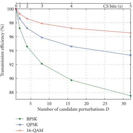
Transmission-Reception Efficiency. A profound insight of the performance
5 10 15 20 25 30 Number of candidate perturbationsD 88
90 92 94 96 98 100
T
ransmission
e
ffi
ciency
(%)
CS bits (s)
0 1 2 3 4 5
BPSK QPSK 16-QAM
Figure7: Transmission-reception efficiency for SA for increasing D,N=M=5,Nt=7, QPSK.
respectively. The same 5×5 MIMO system is considered but in this case a subframe-based optimization of the symbol allocation is employed as the one analyzed in Section 5. A subframe length of Nt = 7 time slots is assumed which derives a number ofL =35 data symbols per subframe. In Figure 6the performance of MMSE precoding is shown for a total transmitted SNR of 20 and 25 dB and the performance of V-BLAST is included for transmitted SNR per antenna of 20 dB. It can be seen that for low values ofDthe performance gain for increasingDis significant while at higher values of D = 8 andD = 16 this benefit saturates. Considering the transmission efficiency diagram of Figure 7 and especially the curve for QPSK modulation of the CS bits it can be seen that the reduction in efficiency is considerable between D = 16 and D = 32. Therefore it can be concluded that for the system investigated in the majority of simulations in this paper, for which Nt = 7 and N = M = 5, the value of D = 16 provides a favorable performance-to-efficiency tradeoff. Hence, unless stated otherwise it is the one used in the following simulations. For this case the relevant transmission-reception efficiency of (17) isE =94.6%. It is apparent inFigure 7that the transmission efficiency can be increased by using 16QAM modulation which for this value ofDgivesE =97.22% in the graph yielding less than 3% of overhead.
8.3. Further Performance Investigation. The SER versus
trans-mitted SNR performance for MMSE is shown in Figure 8 for the same system of N = M = 5,Nt = 7. The graph depicts the performance for both mapping mechanisms of Section 3, namely reordering and scrambling and it can be seen that for the same value ofDboth perform identically. Hence the results confirm that as mentioned above, it is the value ofDthat makes the difference in performance rather
0 5 10 15 20 25 30
100
10−1
10−2
10−3
TransmittedEb/N0n(dB)
SER
MMSE
MMSE-SA reorderingD=64 perfCS MMSE-SA scramblingD=64 perfCS MMSE-SA reorderingD=64 MMSE-SA scramblingD=64 MMSE-SA reorderingD=16 MMSE-SA scramblingD=16 MMSE-SA EDD=64 perfCS
Figure8: SER versus SNR for MMSE, MMSE-SA with reordering or scrambling, projection-based optimisation and MMSE -SA with Euclidean distance (ED) optimisationN=M=5,Nt=7, QPSK.
that the mapping method used. Moreover, to illustrate the superiority of the proposed projection criterion (15) over the Euclidean distance (ED) criterion (14) for the selection of popt, the performance of the latter is also included for the case of error-free CS. It can be seen that the ED criterion only provides a minimal improvement with respect to the performance of the conventional system, while the existence of constructive interference for the proposed criterion offers a notable improvement. The performance of the system with error-free CS transmission is also depicted for comparison. It can be viewed that the negative impact of the CS transmission on the performance of the system is apparent at low SNR values where CS detection is problematic, while it becomes negligible for higher SNRs where the CS detection is reliable. As a result, for low SNRs the proposed technique is outperformed by conventional MMSE precoding due to the unreliability of the CS transmission. However, for the higher SNR values a considerable SER reduction can be observed which yields a 2 dB gain in the transmitted SNR forD=16 for this 5×5 MIMO system. A 2.5 dB gain can be attained by allowing a reduction of the transmission efficiency using D=64 for the same system.
5
0 10 15 20 25
10−1
10−2
10−3
10−4
BE
R
100
SNR per bit per rx antenna
V-BLAST
V-BLAST-SA re-ordering perfCS V-BLAST-SA scrambling perfCS V-BLAST-SA re-ordering V-BLAST-SA scrambling V-BLAST-SA-ED perfCS
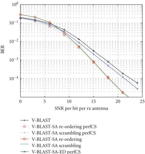
Figure 9: BER versus SNR for V-BLAST, V-BLAST-SA with reordering or scrambling, projection-based optimisation and V-BLAST-SA with Euclidean distance (ED) optimisationN=M=5, Nt=7,D=16, QPSK.
CS transmission is also included for comparison and it is obvious that the negative impact of the CS transmission on the performance of the system only exists at low SNR values. At higher values an SNR gain of 5 dB can be viewed for V-BLAST-SA compared to conventional V-BLAST. Notably the BER reduction for SNR = 20 dB is of an order of a magnitude which consists of a worthwhile improvement for this small scale MIMO system. Again the performance of the ED criterion (14) for the selection ofpopt, is also shown for comparison. Clearly, the proposed criterion benefits from allowing constructive interference in comparison to the ED criterion.
Figure 10 shows the BER performance for increasing number of antennas for the symmetric (M = N) MIMO channel for the case of V-BLAST and V-BLAST-SA. Two sets of results are shown for the cases when the SNR per rx antenna takes the values of 10 dB and 15 dB. It can be seen that for practical values ofN =2 toN =6 for point-to-point MIMO systems the proposed scheme considerably improves the performance of the conventional system. One can observe that the BER is improving up to a certain N for both techniques. This is because the SNR per receive antenna is considered here, which for increasing antennas derives increasing total SNR. Therefore the performance naturally increases up to a certain point where the ICI becomes dominant in the system. Overall the proposed scheme outperforms conventional V-BLAST for all values ofN.
In all simulations above the CSI is assumed perfectly known at the transmitter. However the processing of the
10−1
10−2
10−3
10−4
BE
R
100
1 2 3 4 5 6 7 8
N
V-BLAST V-BLAST-SA
SNR per rx antenna=10 dB
SNR per rx antenna=15 dB
Figure10: BER versusN for V-BLAST, V-BLAST-SA for SNR per rx antenna=10 dB and 15 dB,N=M,Nt=7, QPSK.
V-BLAST-perfect CSI V-BLAST-SA-perfect CSI V-BLAST-e=10%
V-BLAST-SA-e=10% V-BLAST-e=20% V-BLAST-SA-e=20% 5
0 10 15 20 25
10−1
10−2
10−3
10−4
BE
R
100
SNR per bit per rx antenna
Figure 11: BER versus SNR for V-BLAST, V-BLAST-SA for CSI errorse =0,e=10%,e =20%,N =M=5,Nt =7,D=16, QPSK.
these errors are simulated by adding a complex random devi-ation to the channel coefficients available at the transmitter to derive an error in the estimated coefficients of
e=
hm,n−hm,n hm,n
. (25)
Herehm,ndenotes the flat fading channel coefficient between the nth transmit and themth receive antennas while hm,n represents the corresponding channel estimate. Results for e = 10% and e = 20% are shown and for reasons of comparison the performance graphs for perfect CSI are retained in the figure. It can be seen that the performance of the proposed V-BLAST-SA degrades in the same way as conventional V-BLAST for increasing CSI errors. In all cases V-BLAST-SA still outperforms conventional V-BLAST for the higher SNR values when CS detection is reliable.
9. Conclusions and Future Work
The use of static data-to-antenna allocation leads to waste of useful energy inherent in the communication channel and makes conventional MIMO schemes suboptimal. By applying adaptive mapping on the data to be transmitted and introducing diversity in the interference between the transmitted symbols of the MIMO channel this work has shown that significant performance benefits are gleaned for MIMO systems. The tradeoffto this improvement is the need for control signaling for the correct data detection. Further work can be carried out towards reducing the CS overhead and applying the proposed scheme to further and more advanced MIMO techniques including resource allocation.
Acknowledgments
This work has been jointly funded by EPSRC and Philips Research Labs, UK. The authors would like to thank Dr. Tim Moulsley for the helpful discussions throughout this research contribution.
References
[1] G. Caire and S. Shamai, “On the achievable throughput of a multiantenna Gaussian broadcast channel,”IEEE Transactions on Information Theory, vol. 49, no. 7, pp. 1691–1706, 2003. [2] E. Viterbo and J. Boutros, “A universal lattice code decoder
for fading channels,”IEEE Transactions on Information Theory, vol. 45, no. 5, pp. 1639–1642, 1999.
[3] O. Damen, A. Chkeif, and J. C. Belfiore, “Lattice code decoder for space-time codes,”IEEE Communications Letters, vol. 4, no. 5, pp. 161–163, 2000.
[4] G. J. Foschini, “Layered space-time architecture for wireless communication in a fading environment when using multi-element antennas,”Bell Labs Technical Journal, vol. 1, no. 2, pp. 41–59, 1996.
[5] P. W. Wolniansky, G. J. Foschini, G. D. Golden, and R. A. Valenzuela, “V-BLAST: an architecture for realizing very high data rates over the rich-scattering wireless channel,” in Proceedings of the URSI International Symposium on Signals,
Systems, and Electronics (ISSSE ’98), pp. 295–300, October 1998.
[6] T. Haustein, C. von Helmolt, E. Jorswieck, V. Jungnickel, and V. Pohl, “Performance of MIMO systems with channel inversion,” in Proceedings of the 55th Vehicular Technology Conference (VTC ’02), pp. 35–39, Birmingham, Ala, USA, May 2002.
[7] C. B. Peel, B. M. Hochwald, and A. L. Swindlehurst, “A vector-perturbation technique for near-capacity multiantenna multiuser communication—part I: channel inversion and regularization,”IEEE Transactions on Communications, vol. 53, no. 1, pp. 195–202, 2005.
[8] M. Tomlinson, “New automatic equaliser employing modulo arithmetic,”Electronics Letters, vol. 7, no. 5-6, pp. 138–139, 1971.
[9] H. Harashima and H. Miyakawa, “Matched-transmission technique for channels with intersymbol interference,”IEEE Transactions on Communications, vol. 20, no. 4, pp. 774–780, 1972.
[10] U. Erez, S. Shamai, and R. Zamir, “Capacity and lattice strategies for canceling known interference,”IEEE Transactions on Information Theory, vol. 51, no. 11, pp. 3820–3833, 2005. [11] H. El Gamal, G. Caire, and M. O. Damen, “Lattice coding and
decoding achieve the optimal diversity-multiplexing tradeoff of MIMO channels,”IEEE Transactions on Information Theory, vol. 50, no. 6, pp. 968–985, 2004.
[12] M. H. M. Costa, “Writing on dirty paper,”IEEE Transactions on Information Theory, vol. 29, no. 3, pp. 439–441, 1983. [13] F. Rashid, K. J. R. Liu, and L. Tassiulas, “Transmit
beam-forming and power control for cellular wireless systems,”IEEE Journal on Selected Areas in Communications, vol. 16, no. 8, pp. 1437–1449, 1998.
[14] R. W. Heath, S. Sandhu, and A. Paulraj, “Antenna selection for spatial multiplexing systems with linear receivers,”IEEE Communications Letters, vol. 5, no. 4, pp. 142–144, 2001. [15] M. Gharavi-Alkhansari and A. B. Gershman, “Fast antenna
subset selection in MIMO systems,” IEEE Transactions on Signal Processing, vol. 52, no. 2, pp. 339–347, 2004.
[16] S. Sanayei and A. Nosratinia, “Antenna selection in MIMO systems,”IEEE Communications Magazine, vol. 42, no. 10, pp. 68–73, 2004.
[17] W. Yu, W. Rhee, S. Boyd, and J. M. Cioffi, “Iterative water-filling for Gaussian vector multiple-access channels,” IEEE Transactions on Information Theory, vol. 50, no. 1, pp. 145– 152, 2004.
[18] W. Yu, W. Rhee, and J. M. Cioffi, “Optimal power control in multiple access fading channels with multiple antennas,” in Proceedings of the International Conference on Communications (ICC ’01), pp. 575–579, June 2001.
[19] Y. H. Pan, K. B. Letaief, and Z. Cao, “Dynamic spatial subchan-nel allocation with adaptive beamforming for MIMO/OFDM systems,”IEEE Transactions on Wireless Communications, vol. 3, no. 6, pp. 2097–2107, 2004.
[20] C. Masouros and E. Alsusa, “Two-stage transmitter precoding based on data-driven code-hopping and partial zero forcing beamforming for MC-CDMA communications,”IEEE Trans-actions on Wireless Communications, vol. 8, no. 7, pp. 3634– 3645, 2009.
[21] C. Masouros and E. Alsusa, “Interference exploitation using adaptive code allocation for the downlink of precoded multiple carrier code division multiple access systems,”IET Communications, vol. 2, no. 9, pp. 1118–1130, 2008.
systems,”IEEE Transactions on Wireless Communications, vol. 8, no. 3, pp. 1396–1404, 2009.
[23] P. Patel and J. Holtzman, “Analysis of a simple successive interference cancellation scheme in a DS/CDMA system,” IEEE Journal on Selected Areas in Communications, vol. 12, no. 5, pp. 796–807, 1994.