21 |
P a g e
CFD ANALYSIS ON WIND BLADE
Lalit Kumar Gaur
1, Dr.M.K.Gaur
2, Prof.C.S.Malvi
31
M.Tech Scholar (Mechanical Engineering),
2Professor & Guide, M.I.T.S, Mechanical Engineering, Gwalior (M.P.), India
3Professor & HOD, Mechanical Engineering, Gwalior (M.P.), (India)
ABSTRACT
This review paper aims at to move forward in this research on blade. In which I have critically analyzed few paper.
At last my work deals with 3d analysis of wind turbine with fluid and solid interference using NACA profile
parameters on CFD and static structure analysis. Objective of this review is angle of attack, wind blade material,
twisting of blade airfoil, Vibration on blade and selection of Blade airfoil. ‘Wind Power’ When calculating any
change to the design of a wind turbine, it is critical that the designer evaluate the impact of the design change on the
system cost and performance. The wind turbine tower and the ground are not included in the flow model and a
uniform wind speed profile is assumed at the entrance of the domain.
To generate the volume mesh for the three blade rotor, the 1200 periodicity of the rotor is exploited by only meshing the volume around one blade. The remaining two blades are included in the computations through the use of
periodic boundary conditions. The active part of the blade is extended to the hub, following the design tendencies of
modern wind turbines.
The wind turbine tower and the ground are not included in the flow model and a uniform wind speed profile is
assumed at the entrance of the domain. The aerodynamics of HAWT are investigated using a commercial FEM and
CFD code. The Specifications of an existing middle-sized turbine starting from the classical Blade Element
Momentum (BEM) method is adopted for the design of the rotor. The active part of the blade is extended to the hub,
following the design tendencies of modern wind turbines.Angle of Attack of wind was a 4° acting on 3D model the
wind turbine blade which airfoil based on the S809. The action of flow through the airfoil blade was the
aerodynamic flow of wind on the result at simulation. The CFD analysis done give the stream line result generate on
the lifting force and drag force. The static structure analysis of blade like cantilever beam was also be analysis, the
CFD pressure transfers to the static structure model.
I INTRODUCTION
The development of any nation can be indicated by its per capita energy consumption. A developing country like
India, with much lower per capita energy consumption as compared to that of developed nations, will have to look
for better sustainable power to fulfill its higher Energy requirements to cope up with higher and appreciable
industrial production growth for future without degrading its environment balance. This limitation of traditional
fossil fuels and the environmental aspects of conventional power sectors have resulted in the realization that greater
importance be given to the energy conservation, energy efficiency and non-conventional energy sources, i.e.
22 |
P a g e
Wind is an indirect source of solar energy. It is caused by the uneven heating of the earth by the sun and the resultingredistribution of air to equalize energy in the atmosphere moving air from areas of high pressure to areas of lower
pressure. A „wind turbine‟ converts the power in the wind into electricity, whereas „windmill‟, converts the wind‟s
power into mechanical power.
Research on wind turbine is considerable increase day to day. Tavares Silva et al [2013] has suggested that the
another investigation field present in to a wind turbine that is Loewy‟s lifting deficiency Function (LDF), also called
as Returning Wake Model, which is connecting to the Blade Element Momentum method (BEM). The Comparison
of wind turbin between GH blade and BEM NE Blade in different wind speed.
A. Jadallaha et al [2014] has give that the major point in wind turbine performance is Blade Element Method and
Momentum theory Which gives some important parameter like tip speed Ratio, Pitch angle, Number of blade and
wind speed. For low power wind turbine above parameter acts as a basis fundamental on blade design. The
Optimization of wind turbine performance calculation based on Low wind speed to high wind speed by the
changing of Pitch angle , angle of attack and tip speed Ratio.
Shah et al [2013] has suggested that in low speed turbine, the blade designs have another parameter, which is a blade
material in a manufacturing point of view. Light in weight and load Carrying capacity of material use to
manufacturing of turbine blade. There are two type of material use to manufacturing of blade (1) Flax (Polyester)
And (2) E-Glass (Fiber mass 45%) as reinforcement. Component weight of blade manufacture Flax Blade is light
and to the greatest extent of loading condition. Recommend that Flax/Polyester is suitable for low power generating
wind turbine blade.
SrinivasG et al [2014] has suggested that blades play an important role in converting wind energy into electrical
energy. When the Wind attack to the blade, reaction force produce in form of lift and drag forces , this Forces are
Calculated by Numerical method but because of complication and also it is a tedious work we can also go for
another method , That is Computation Fluid Dynamics (CFD) method for getting desired results. CFD method is
based on fluid mechanics, Its Function is to use blade air-profile and consider a 2 dimensional profile Choose by
Design Foil Workshop for various chords (Abbott et al Report No.824) at different Angle of Attack of air and also in
Different Reynold No. In Design Of wind turbine, gearbox also a decisive component and some time it is failure in
running condition. When shutdown condition coming into the wind turbine, load suddenly increase in the Gearbox
teeth. The varying capacity in Gearbox is study by Y. Guo et al [5].
AdityaRachmanet al [2013] has compare between Horizontal and vertical axis wind turbine with rounded shroud
device, which is working as a diffuser at a flow of air inside to it. Flow of air into shroud, the horizontal axis wind
turbine gives more performance as compare to vertical axis wind turbine. There is no contribution of shroud in
vertical axis wind turbine
Armaghan Ahmad et al [2013] has suggested that the wind turbine is model made on field area and tested with the
practical condition, This process is a wastes of material and time . This process also can be performed on
CAD-CAM modeling and Analysis software with using Mod-5B and NACA 4415 blade profile. CAD-CAD-CAM process is a
23 |
P a g e
and fast to get result on this software.The profile of wind blade is NACA4415 is used to Test on CAD CAMSoftware and get the Result for 5 kW wind turbine.
The demand for the power around the world is continuously increasing very rapidly, as the stock of conventional
sources of energy (i.e. fossil fuels) is limited and decreasing very fast and the earth‟s ecological balance is being
damaged beyond its sustainable limit.Wind energy is a source of renewable power which comes from air current
flowing across the earth's surface. Wind turbines harvest this kinetic energy and convert it into usable power which
can provide electricity for home, farm, school or business applications on small (residential), medium (community),
or large (utility) scales [1].
Generally there are two main types of wind turbine i.e. Horizontal axis wind turbine and Vertical axis wind turbine.
The rotation of shaft is parallel to the ground is called as Horizontal axis wind turbine and the rotation of shaft is
perpendicular to the ground is called as Vertical axis wind turbine.
Horizontal Axis wind turbines have a better efficiency as compare to the Vertical Axis wind turbine. HAWT produce
more electricity at wide range farm in any type of field at both low and high speed of the wind. Maximum industries
is working on this sector and doing optimized of wind turbine in every parameter. Mainly the focuses of
optimization in wind turbine are the blade and rotor size. Blade parameter are tip speed ratio, twisting angle, chord
length, pitch angle and lift & drag coefficient, that are the point to optimized the blade for maximize the blade
efficiency at every condition of wind [6].
II MATERIAL SELECTION
Selection of material of wind turbine blade is also the main property function in the efficiency of the blade turbine
design. There are many materials available in the market which can be use to select the material, but in the
observation of deferent material we select the carbon fiber 395 as a blade material. Carbon fiber 395 has some
benefits which cause we selected:
Low material density
Excellent Stiffness
Higher graphitization level
Elevated temperature performance
1.1
Method
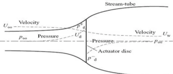
Betz law [7] was first formulated by the German Physicist Albert Betz in 1919. Betz law can be used to determine
the power from an ideal turbine rotor, the thrust of the wind on the ideal rotor and the effect of the rotor operation on
the local wind field. This simple model is based on alinear momentum. The law states that it is only theoretically
possible to convert a maximum of 59.3% of the kinetic energy in the wind to mechanical energy using a wind
turbine, and that this maximum power output occurs when the downstream wind has 1/3 the speed of the upstream
24 |
P a g e
Figure 2 Pressure and Velocity evolution through the actuator disk
Power generated due to wind speed is given by following equation.
Where, Pw= Power of wind (watt)
ρ = Air density (Kg/m3) (1.225 Kg/m3)
A= Area of segment of the wind being considered
u = Undistributed wind speed (m/s).
Cp=Coefficient of Power =16/27 (According to Betz)
Wind Turbine need a calculation for a blade which is the main preference for designing and the basic principal is
blade element momentum (BEM) theory who gives the angle of twist and Chord length of Airfoil of blade. Better
performance of blade, design parameter includes airfoil shape, design angle of attack, design tip speed ratio and
wind speed which are the parameter design consideration of aerodynamic design blade. BEM theory is capable to
use for valuation of forces on blade for design, optimization and calculation of steady load.
Figure 3: Schematic of Blade
C = Airfoil chord length
dr = Radial length of element
r = Radius
R = Rotor radius
Ω = Angular velocity of rotor
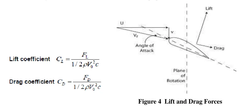
The angle of attack is the angle between relative velocity of wind and chord length. For getting the performance of
25 |
P a g e
to the plane of rotation. It is the first characteristics in choose of airfoil and for high lift to drag ratio determine bythe angle of attack, the blade‟s angle with respect to the apparent wind, the blade‟s shape and its ratio. In this paper
we consider 4ᵒ as a angle of attack. The air attack to the blade at the reference line of blade is called chord line.
The basic coefficient of forces are working on blades are lift coefficient and drag coefficient which are acting at the
tangential force and longitudinal force on the blade. This forces are perpendicular to the direction of wind flow.
Figure 4 Lift and Drag Forces
III PARAMETER USED
The design parameters are calculated as per formulas use in design of blade. In this paper we are consider S809
profile of blade and done 14 segment of blade for the more consideration of the result. Design blade parameters and
airfoil of blade from hub to root figure are given below which are uses to modeling of wind turbine blade.
IV RESULT & DISCUSSION
Above airfoils are kept in modeling software (Solidwork) and make 3D model of blade which is interact with the
environment. The angle of attack of air is 4ᵒ maintain in the environment. The Whole model is transfer to the ansys
fluent software and meshing the geometry on it that is show in figure below.
26 |
P a g e
The Environment domain type is air and fluid type is Air ideal Gas that all consider parameter in ansys Fluent
workbanch, also we define inlet an outlet parameter in the geometry[5]. The Experimental velocity of air is 9m/s and
pressure velocity scheme is consider as sample with spatial discretization gradient is least squares cell based and
wind momentum is to be Second order upwind [2,3]. Define all boundary condition, after that initialized the solution
from the inlet and start the calcultaion. After calculation we get the result the streamline flow of air and pressure
conture show in figure.
Presure is produce the forces which is acting on a blade and that is maximum 122.82 Pa and this forces
transfer in to static structure model as consider the cantilever beam.
Figure 9 Velocities Streamline of Air Figure 10 Pressure Contour in Blade
CFD Load Transfer Summary for Static Structure Analysis
There are the following results and figure:
Object Name Equivalent Stress Equivalent Elastic Strain Total
Deformation
Maximum 1.2007e+005Pa 1.9360e-004 m/m 3.30e-002 m
CFD Computed Forces from CFD Results File
Mechanical Mapped Forces for Mechanical
Surface
X-component = 160.20 N
Y-component = -606.70 N
Z-component = 28.860 N
27 |
P a g e
Figure 11 Force Distribution From Blade Figure 12 Stress Distribution Analysis
Figure 13 Strain Distribution Analysis Figure 14 Total Deformation Analysis
V CONCLUSION
For CFD analysis of wind blade is done on ansys fluent software and the static structure module use for static
analysis .The horizontal axis wind turbine blade with airfoil S809 is design at different parameter and analysis of
wind flow.. Figure 9-10 shows the stream line distribution of wind into the blade and also more concentrating area.
The wind velocity of angle of attack is 4ᵒ at 9m/s and that developed pressure contour in the blade. The pressure is
converted into the force parameter and study of static structure analysis of blade at considers a cantilever bean. The
blade hub portion is fixed and the forces distribute over the blade at CFD load transfer to static structure module as
show in figure 11. The Analysis of static structure, Stress, strain and deformation result got.
REFERENCE
[1] Ravi Anant Kishore, Thibaud Coudron, Shashank Priya “Small-scale wind energy portable turbine (SWEPT)”
United States , 2013.
[2] Kim B, Kim J, Kikuyama K, Rooij V, Lee Y 3D numerical prediction of horizontal axis wind turbine power
characteristics of the scales delft university T40/500 model, the fifth JSME-KSME fluids engineering
28 |
P a g e
[3] Mandas N, Cambuli F, Carcangiu CE, Numerical prediction of horizontal axis wind turbine flow, Europeanwind energy conference, Athens, Grecce.
[4] Mr. Monir Chandrala , Prof. Abhishek Choubey and Prof. Bharat Gupta, 2012, Aerodynamic Analysis Of
Horizontal Axis Wind Turbine Blade, International Journal of Engineering Research and Application, Vol. 2,
Issue 6, Nov.-Dec. 2012, pp. 1244-1248.
[5] Ansys CFD tutorial.
[6] Aditya Rachman, La Aka Muhtar, Silvianus Levi, and Natanael Salea, 2013, An Experiment on Horizontal and
Vertical Wind Turbines with Incorporation of Rounded Shroud Device Using Wind Simulation in a Vehicle,
International Journal of Innovation and Applied Studies ISSN 2028-9324 Vol. 3 No. 2 June 2013, pp. 365-374.
[7] Srinivas G , Mahesha G T, Chethan K N and Arjun N, 2014, Analysis of Wind Turbine Blade, International
Journal of Current Engineering and Technology E-ISSN 2277-4106,P-ISSN 2347-5161.
[8] Dr. Abdullateef A. Jadallaha, Dr .Dhari Y. Mahmoodand Zaid A. Abdulqader, 2014, Optimal Performance of
Horizontal Axis Wind Turbine for Low Wind Speed Regime, IISN: 2321-3124.
[9] Darshil U. Shah, Peter J. Schubel and Mike J. Clifford,2013, Can flax replace E-glass in structural composites?
A small wind turbineblade case study, Composites: Part B 52 (2013) 172-181.
[10] Cláudio Tavares Silva and Maurício Vicente Donadon, 2013, Unsteady Blade Element-Momentum Method
Including Returning Wake Effects, J. Aerosp. Techno lManag. Sao Jose dos Campos, Vol.5, N 1. Pp. 27-42,
Jan-Mar. 2013.
[11] Y. Guo, J. Keller, T. Moan and Y. Xing, 2013, Model Fidelity Study of Dynamic Transient Loads in a Wind
Turbine Gearbox, Conference paper NREL/CP-5000-58414 april 2013.
[12] Armaghan Ahmad, Zohaib Elahi, Muhammad Babar,2013, CAD-CAE Integration of Horizontal Axis Wind
Turbine, Advances in Energy and Power 1(2): 56-61, 2013.
[13] Fei-Bin Hsiao , Chi-Jeng Bai and Wen-Tong Chong,2013, The Performance Test of Three Different Horizontal
Axis Wind Turbine (HAWT) Blade Shapes Using Experimental and Numerical Methods, Energies
2013,6,2784-2803;doi:10.3390/en6062784.
[14] P. Santhana Kumar, A. Abraham, R. Joseph Bensingh and S. Ilangovan, 2013, Computational and Experimental
Analysis of a Counter-Rotating wind Turbine System ,Journal of science and Industry Research Vol. 72 , may
2013, pp.300-306
[15] Paramet Pathike, Thanad Katpradit, Pradit Terdtoon and Phrut Sakulchangsatjatai, 2013, a new design of blade
for small horizontal-axis wind turbine with low wind speed operation, Energy Research Journal 4 (1) : 1-7,2013,
ISSN: 1949-0151.
[16] Ravi Anant Kishore, Thibaud Coudron, Shashank Priya, 2012, Small-scale wind energy portable turbine
(SWEPT), J. Wind Eng. Ind. Aerodyn. 116 (2013) 21–31]
[17]
Large eddy simulation of the wind turbine wake characteristics in the numerical wind tunnel model,Jang-Oh Moa, Amanullah Choudhry , Maziar Arjomandi , Young-HoLee, 2013, Large eddy simulation of the wind