ISSN(Online): 2320-9801
ISSN (Print) : 2320-9798
I
nternational
J
ournal of
I
nnovative
R
esearch in
C
omputer
and
C
ommunication
E
ngineering
(An ISO 3297: 2007 Certified Organization)
Vol. 4, Issue 3, March 2016
Phase Shifter using RF MEMS Capacitive
Shunt Switch
Ketaki Jadhav1, Gishnu Rahul2, Rohit Parvatikar3, Sunil Goudar4, Prof.Vaibhav Kshirsagar5
B.E Student, Department of EXTC, Vidyalankar Institute of Technology, University of Mumbai, India1,2,3,4
Professor, Department of EXTC, Vidyalankar Institute of Technology, University of Mumbai, India5
ABSTRACT: This paper presents the design and working of a phase shifter using the RF MEMS (micro electro-mechanical system) technology. The phase shifters designed are electrostatically actuated and developed using the concept of RF MEMS switches. The use of coplanar waveguide (CPW) for the transmission of signal is taken into consideration. The phase shift is obtained by controlling the number of beams with the CPW structure. The displacement of the beam is considered using COMSOL whereas the change in the phase of the signal is observed using ANSOFT HFSS (ANSYS) by studying the S parameters of the signal. The design parameters considered includes the beam length, air gap, dielectric material, frequency of operation. The experimental results show that by increasing the number of beams the phase shift of the signal increases. The use of this technology is very efficient as it gives a return loss of less than 20dB with an insertion loss of less than 0.1dB in the frequency range of 0-20GHz.
KEYWORDS: RFsignal, MEMS, Coplanar waveguide, S parameter, insertion loss.
I. INTRODUCTION
1].PHASE SHIFTER
Phase shifter is a microwave network in which the phase of electromagnetic wave of a particular frequency can be shifted when propagating through a transmission line. A microwave phase shifter is a device used to vary the phase of a electromagnetic oscillations at the output of microwave transmission line with respect to the phase of the oscillations given at the input of the line. Thus the phase shift occurs due to change in the electrical length of the transmission line[3].
Ideally phase shifters provide an output signal with an equal amplitude to the input signal, any loss in the amplitude is due to the insertion loss of the component. The input signal is shifted in phase at the output based on the configuration of the phase shifter selected. There are three main types of phase shifters:
1) Digital Phase Shifter –These phase shifters are digitally controlled. They are programmable or can by controlled via a computer interface. USB phase shifters are a relatively new form factory, which enables the phase shit of the device to be controlled from a computer.
2) Analog Phase Shifter –The phase shift in analog phase shifters is typically controlled by a voltage level. The phase shift change based on the tuning voltage is specified for the phase shifter.
3) Mechanical Phase Shifter –The phase shift of the device is controlled manually with a knob. The phase from the input to the output is adjusted by turning a knob.
2].RF MEMS
ISSN(Online): 2320-9801
ISSN (Print) : 2320-9798
I
nternational
J
ournal of
I
nnovative
R
esearch in
C
omputer
and
C
ommunication
E
ngineering
(An ISO 3297: 2007 Certified Organization)
Vol. 4, Issue 3, March 2016
phase shifter. Employing, capacitive switches in phase shifters can considerably reduce losses, size, therefore scaling down the area of phased array antenna where thousands of phase shifters are mounted.[2]
Depending on the application, design approach of phase shifter is classified into two categories viz., analog and digital. In analog approach, continuously varying phase shift is obtained from 0 to 360° and fabricated using MEMS varactors while in digital approach, discrete set of phase delays are obtained and fabricated using MEMS switches.[1]
3].RF MEMS SWITCH
RF MEMS switches are surface micro-machined devices which use a mechanical movement to switch on or off in the RF transmission line, designed to operate at RF frequencies up to millimeter wave frequencies (0.1 to 40 GHz).
RF MEMS switches are built using advanced surface micro-machining fabrication techniques, resulting in tiny microscopic mechanical switch structures, which offer the ultimate in RF performance. The key advantages over conventional switches include low power consumption, high isolation, low insertion loss, high linearity, reliability and low cost[5].
There are two types of RF contact switches: 1) Ohmic contact
2) Capacitive contact
For the ohmic switch two metal electrodes are brought into contact to create a low resistance connection. While for a capacitive switch a metal membrane is pulled down on a dielectric layer by means of electrostatic which forms a capacitive sandwich.
4].RF MEMS PHASE SHIFTER
The insertion loss of RF MEMS phase shifters is usually several dB less than that of transistor-based phase shifters, especially at millimeter wave frequencies. This allows multiple phase shifters and antenna elements of a phased array radar or communications system to be driven by the same transmitter power amplifier, thereby saving cost and power consumption. For additional cost saving, RF MEMS phase shifters can be integrated with antenna elements on the same glass or ceramic substrate.[3]
II. RELATED WORK
ISSN(Online): 2320-9801
ISSN (Print) : 2320-9798
I
nternational
J
ournal of
I
nnovative
R
esearch in
C
omputer
and
C
ommunication
E
ngineering
(An ISO 3297: 2007 Certified Organization)
Vol. 4, Issue 3, March 2016
COPLANAR WAVEGUIDE
Coplanar waveguide (CPW) is a planar transmission line. In this Signal line and two ground lines are on the same plane. The Z0 of the line is determined by G/W/G dimension. The parameters considered for the designing of the coplanar waveguide are:
Relative permittivity of Si substrate=11.9 Height of substrate=20um
G/W/G=25/44/25
Thickness of conductors=2um
Using these values the impedance of the waveguide is obtained as: Impedance(Z0)=52.79 ohms
The design parameters considered for the phase shifter structure along with their values for its operation in the range of 0-20GHz are:
DESIGN PARAMETERS VALUES
Number of bridges 1
Beam length 130um
Beam thickness 2um
CPW configuration 25/44/25
Dielectric thickness 0.5um
Air gap 2.5um
ACTUATION VOLTAGE
When the bias voltage is increased, the system becomes unstable and the bridge collapses suddenly when the deflection reaches one third of the gap height. This voltage, which results in the point of instability, is called the pull-down voltage. The applied bias voltage between the MEMS bridges and bottom electrodes changes the height of the MEMS bridges, which in turn varies the distributed MEMS capacitance. This results in a change in the loaded transmission line impedance and phase velocity, which in turn causes phase shift.
The actuation voltage can be reduced by decreasing the bridge height or adopting bridge materials with a relatively low elastic modulus such as polymer. However, it is not advisable to decrease the height of the MEMS bridges to reduce the actuation voltages because the narrow height makes fabrication difficult and there is a need to keep the bridge height as large as possible to increase the fabrication yield.
ISSN(Online): 2320-9801
ISSN (Print) : 2320-9798
I
nternational
J
ournal of
I
nnovative
R
esearch in
C
omputer
and
C
ommunication
E
ngineering
(An ISO 3297: 2007 Certified Organization)
Vol. 4, Issue 3, March 2016
III.SIMULATION RESULTS
1)MODAL ANALYSIS
Modal Analysis or rather, the Eigen frequency analysis refers to the calculation of natural frequencies of vibration of the beam. Modal analysis is the study of the dynamic properties of structures under vibrational excitation. The Eigen values are used to determine the natural frequencies (or Eigen frequencies) of vibration, and the eigenvectors determine the shapes of these vibrational modes. Modal Analysis aids in computing the values of these mechanical resonant frequencies of vibration of the beam. FEM simulations employing COMSOL Multiphysics provides the deformed shapes of the beam when subjected to the various modes of vibration. The simplified governing equation has been written as under-
f0 =
π (i)
m = 0.35(lwt)ρ ... (ii)
where,
f0=natural frequency of vibration (in Hz),
k=spring constant of the beam ,
m=mass of the beam (in kg),
l=length of the beam
w=width of the beam
t=thickness of the beam
ρ=density of gold=19,320kg/m3.
In order to perform accurate Modal Analysis in COMSOL Multiphysics, the various application modules used are- a) MEMS Module
Structural Mechanics Eigen frequency analysis b) COMSOL Multiphysics Deformed Mesh
Moving Mesh (ALE) Static Analysis
The displacement of the cantilever beam under different actuation voltages gives the following outcomes. It is observed that the actuation voltage is below 12V.
-3 -2.5 -2 -1.5 -1 -0.5 0
0 20 40 60 80 100 120 140
ISSN(Online): 2320-9801
ISSN (Print) : 2320-9798
I
nternational
J
ournal of
I
nnovative
R
esearch in
C
omputer
and
C
ommunication
E
ngineering
(An ISO 3297: 2007 Certified Organization)
Vol. 4, Issue 3, March 2016
2)ELECTROMAGNETIC SIMULATIONS
The electromagnetic analysis of the phase shifter is done by using HFSS. The key characteristics of the RF MEMS switch are insertion loss, isolation, and actuation voltage. The aim is to increase the RF parameters while reducing the actuation voltage. A MEMS switch in upstate and downstate position is shown in fig. 2(a) and fig. 2(b) respectively.
a)Upstate simulation
The switch structure is simulated in the upstate position by HFSS simulator. There is CPW which contains transmission line, a substrate, and grounds. There cantilever beam situated on top of the CPW is at the air gap distance from the ground plane. The S parameters are taken from the range of 0-20 GHz.
Fig 4(a) Return loss for upstate cantilever beam
The Return loss (S11) is better than 20 dB in the frequency range of 0– 20 GHz, thus minimising the losses incurred.
Fig 4(b) Insertion loss for upstate cantilever beam
Insertion loss (S12 ) is less than 0.1 dB hence the effective transmission of signal takes place in 0-20GHz range.
0.00 2.50 5.00 7.50 10.00 12.50 15.00 17.50 20.00
Freq [GHz] -50.00
-45.00 -40.00 -35.00 -30.00 -25.00 -20.00
d
B
(S
(1
,1
))
HFSSDesign1
Return Loss v/s frequency ANSOFT
m2
Curve Info dB(S(1,1)) Setup1 : Sw eep Name X Y
m2 12.0000 -26.8705
0.00 2.50 5.00 7.50 10.00 12.50 15.00 17.50 20.00
Freq [GHz] -0.08
-0.06 -0.05 -0.04 -0.03 -0.01
d
B
(S
(1
,2
))
HFSSDesign1
Insertion loss v/s Frequency ANSOFT
m1
Curve Inf o dB(S(1,2)) Setup1 : Sw eep
Name X Y
ISSN(Online): 2320-9801
ISSN (Print) : 2320-9798
I
nternational
J
ournal of
I
nnovative
R
esearch in
C
omputer
and
C
ommunication
E
ngineering
(An ISO 3297: 2007 Certified Organization)
Vol. 4, Issue 3, March 2016
Fig 4(c) Variation in phase of cantilever beam in upstate position
b)Downstate simulation
The switch in its downstate position is formed due to the contact of the cantilever beam with the ground plane of the coplanar waveguide. The S-parameters are taken from the range of 0-20 GHz.
Fig 5(a) Return loss for downstate cantilever beam
The return loss for downstate position is even better than upstate position with a value of less than 30dB.
0.00 2.50 5.00 7.50 10.00 12.50 15.00 17.50 20.00
Freq [GHz] -7.50 -6.25 -5.00 -3.75 -2.50 -1.25 0.00 a n g _ d e g (S (1 ,2 )) [ d e g ] HFSSDesign1
Phase v/s Frequency ANSOFT
phas e
Curve Inf o ang_deg(S(1,2)) Setup1 : Sw eep
Name X Y
phase 12.0000-4.3944
0.00 2.50 5.00 7.50 10.00 12.50 15.00 17.50 20.00
Freq [GHz] -55.00 -50.00 -45.00 -40.00 -35.00 -30.00 -25.00 d B (S (1 ,1 )) HFSSDesign1
Return Loss v/s Frequency ANSOFT
m1
Curve Info dB(S(1,1)) Setup1 : Sw eep Name X Y
m1 12.0000 -33.0571
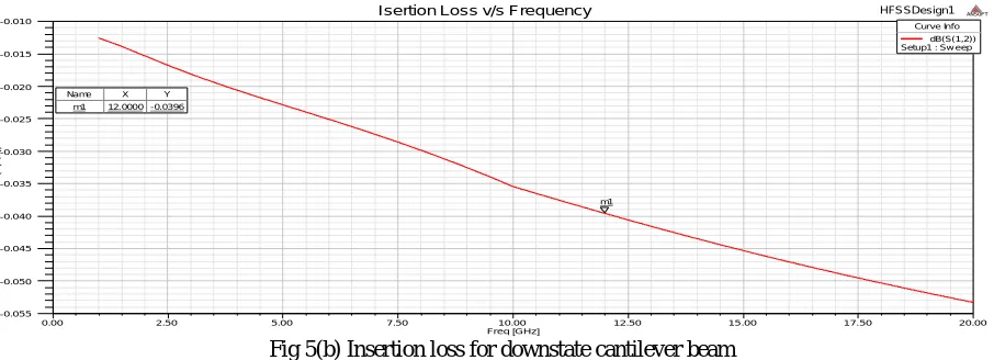
-0.050 -0.045 -0.040 -0.035 -0.030 -0.025 -0.020 -0.015 -0.010 d B (S (1 ,2 )) HFSSDesign1
Isertion Loss v/s Frequency ANSOFT
m1
Curve Info dB(S(1,2)) Setup1 : Sw eep
ISSN(Online): 2320-9801
ISSN (Print) : 2320-9798
I
nternational
J
ournal of
I
nnovative
R
esearch in
C
omputer
and
C
ommunication
E
ngineering
(An ISO 3297: 2007 Certified Organization)
Vol. 4, Issue 3, March 2016
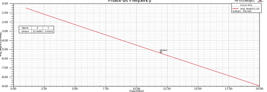
Fig 5(c) Variation in phase of cantilever beam in downstate position
The phase shift obtained with the cantilever structure can be controlled by varying the number of cantilever beams suspended on the coplanar waveguide. The increase in the phase of the signal is obtained by cascading more number of beams in the structure. The results for two cascaded beams have been tabulated along with the single beam structure indicates that the phase shift almost doubles with increase in every beam in the structure.
OPEN BEAM
SHORT BEAM
2 CASCADED OPEN BEAMS
2 CASCADED SHORT BEAMS S21
(DEGREES) -4.4 -5.32 -7.487 -9.665
S11 (dB) -26.79 -32.23 -23 -30.5
IV.CONCLUSION
Despite the fact that MEMS switches operate slower than their electronic counterparts, they are still useful in many applications. One important advantage of MEMS switches is their linearity. Unlike electronic switches made with metal-semiconductor or p-n junctions, the contact area for MEMS switches is perfectly linear. This means that well-designed MEMS switches do not create nonlinearities or distortion such as harmonics or intermodulation products. The electromagnetic simulation results indicated that return loss is better than 20 dB at lower frequency and Insertion loss is less than 0.1 dB which is good enough for the reconfigurable devices. Thus the RF MEMS phase shifters are designed with minimum loss and also produces linear phase shift in the transmitted signal.
V.FUTURE WORK
In wireless communications, radio frequency micro-electro-mechanical systems (RF MEMS) technology is attracting tremendous interest across the world as the needs of frequencies gets higher, data bandwidth gets larger and multiple broadband signals have to be handled in the same device. Compared to other technologies, components based on RF-MEMS provide superior RF performance and tuning, and can perform over a much broader range of operating frequencies. In particular, the RF MEMS switches enable the reconfigurability of RF front-end circuits and their excellent linearity, lower insertion losses and improved isolation recommend them for high frequency applications. Phase shifters and tuneable filters in X to Ka-band frequencies for beam steering/forming of antenna phase arrays and for bandpass or rejection can take full advantage of the RF MEMS switches. The present open challenges of RF MEMS devices are the reliability, the packaging and their 3D integration with RF ICs.
0.00 2.50 5.00 7.50 10.00 12.50 15.00 17.50 20.00
Freq [GHz] -9.00
-8.00 -7.00 -6.00 -5.00 -4.00 -3.00 -2.00 -1.00 0.00
a
n
g
_
d
e
g
(S
(1
,2
))
[
d
e
g
]
HFSSDesign1
Phase v/s Frequency ANSOFT
phase
Curve Inf o ang_deg(S(1,2)) Setup1 : Sw eep
ISSN(Online): 2320-9801
ISSN (Print) : 2320-9798
I
nternational
J
ournal of
I
nnovative
R
esearch in
C
omputer
and
C
ommunication
E
ngineering
(An ISO 3297: 2007 Certified Organization)
Vol. 4, Issue 3, March 2016
REFERENCES
1. Rebeiz, Gabriel M. RF MEMS Theory, design and technique. John Wiley & Sons Inc, 2003, pp. 298-302.
2. Chakraborty, Amrita; Gupta, Bhaskar & Sarkar, Binay Kumar. Design, fabrication and characterization of miniature RF MEMS switched capacitor based phase shifter. Microelectron. J., 2014, 45, 1093-1102.
3. Scardelletti, M.C.; Ponchak, G.E.; Zaman, A.J. & Lee, R.Q. RF MEMS phase shifters and their application in phase array antennas. In the Seventh IEEE Wireless and Microwave Technology, 2005, 191-194.
4. Bansal, Deepak; Kumar, Amit; Sharma, Akshdeep; Kumar, Prem & Rangra K. J. Design of novel compact anti-stiction and low insertion loss RF MEMS switch. Microsys. Techno., 2014, 20(2), 337-340.
5. Barker, N. S. & Rebeiz, G.M. Distributed MEMS true-time delay phase shifters and wide-band switches. IEEE Trans. Microwave Theory Tech., 1998, 48(11), 1881-1890.
6. Rebeiz, Gabriel M. & Muldavin, Jeremy B. RF MEMS switches and switch circuits. IEEE Microwave Magazine, 2001, 2(4), 59-71. 7. Goldsmith C., Kleber J., Pillans B., Forehand D., Malczewski A., and Frueh P. RF MEMS:benefits & challenges of an evolving rf switch
technology. pages 147–148. 2001. doi:10.1109/GAAS.2001.964365.
8. P.D. Grant, M.W. Denhoff, and R.R. Mansour, ―A Comparison between RF MEMS Switches and Semiconductor Switches,ǁICMEMS 2004: MEMS, NANO and Smart Systems, 2004 Proceedings, Aug. 2004, pp. 515- 521.
9. P. Sharma, S.K. Koul, and S. Chandra, ― Studies on RF MEMS Shunt switch,ǁ Indian Journal of Pune & Applied Physics ,Vol.45,April
2007 , pp. 387 – 394.
10. Mafinejad, A.Z. Kouzani, K. Mafinezhad, and D. Izadi, ―Design and Simulation of a RF MEMS Shunt Switch for Ka and VBands and
the Impact of Varying Its Geometrical Parameters,ǁ IEEE International Midwest Symposium, pp. 623 – 626, 2009.
11. ] J. B. Muldavin and G. M. Rebeiz, ―High isolation MEMS shunt switches—Part 2: Design,ǁ IEEE Trans. Microwave Theory Tech.,vol.
48, pp. 1053–1056, June 2000.
12. ] C. Palego, Z. Peng, J. C. M. Hwang, D. Scarbrough, D. I.Forehand, and C. L. Goldsmith, “Compact Ka-band phase shifters using MEMS capacitive switches,” in Proc. European Microwave Conf., Sept. 2009, accepted forpublication.
13. B. Lakshminarayanan, and T. M. Weller, “Design and modeling of a 4-bit slow-wave MEMS phase shifter,” IEEE Trans. Microwave Theory Techniques, vol. 54, pp. 120-127, Jan. 2006.

![Fig 4(a) Return loss for upstate cantilever beam Freq [GHz]](https://thumb-us.123doks.com/thumbv2/123dok_us/1457915.1178628/5.595.62.515.467.635/fig-return-loss-upstate-cantilever-beam-freq-ghz.webp)