Finite element mesh generation of nuclear power plant components including
surface and embedded cracks
M.Hrázský, V.Makýš, VÚJE Trnava Inc., engineeering, design and research company, Trnava, Slovak Republic
ABSTRACT
Fracture mechanics procedures application provides effective and relatively fast critical dimensions determination and acceptance evaluation of cracks located in NPP components. The use of computer codes based on numerical procedures such as finite element method or boundary element method is necessary for this purpose in most cases.
We have dealt with critical crack dimensions assessment applying finite element method computer code ADINA up to now. The preparation of calculation meshes is the most complicated and time consuming step in the crack evaluation sequence. In common cases this task is practically unrealizable using hand-made method creation. Several specialized crack mesh generators (e.g. ORMGEN e.t.c.) generate nice meshes but with unnecessary large number of elements frequently. Therefore we have decided to develop algorithms and computer codes enabling automatic crack “insertion“ into any place of intact original component FE mesh. All this work is carried out within graphic environment of user friendly GiD computer code as a new “problem type”. ADINA input data are generated as a final product of these programmes.
INTRODUCTION
During more than twenty years of our practical activities in the field of crack assessment analyses we have carried out many analyses applying procedures of fracture mechanics. Modern computer programmes utilizing numerical methods such as finite element method or boundary element method provides effective and relatively fast means enabling critical dimensions determination and acceptance evaluation of cracks located in NPP components. The preparation of calculation meshes is the most complicated and time consuming step in the typical crack evaluation sequence. In common cases this task is practically unrealizable using hand-made method creation. Computer code ADINA, which we have applied up to now, offers very wide possibilities regarding any requested calculation modes. Nevertheless the construction of meshes containing various configuration of surface or subsurface cracks in arbitrary places of analysed body seems to be common weak point of any such programme especially in cases demanding manifold repeated “crack mesh generation“.
Some special tasks, e.g. RPV integrity analysis during PTS events, could be solved applying specialized crack mesh generators such as ORMGEN, ORNOZLE etc.. These programmes generate nice meshes but with unnecessary large number of elements frequently. In principle they are not able to be used in general problem solution and therefore we have decided to develop algorithms and computer codes enabling automatic crack “insertion“ into any place of intact original component FE mesh. All this work was carried out within graphic environment of user friendly GiD computer code (academic version) as a new “problem type”. Basic features of developed procedures and recent experience along with some utilization examples shall be presented in the next parts of our paper.
GENERATION OF FEM MESHES INCLUDING CRACKS
Crack Area Insertion Method
The main aim of our work consists in effort to automatize and simplify, as much as possible, the whole crack modelling process and input data preparation in case of finite element method analyses of three-dimensional components containing cracks. Our procedures are applicable on any component FEM meshes or parts of meshes containing 3D 20-node isoparametric elements in locations where cracks are to be present.
The basic idea of crack area insertion method consists in the replacement of conventional 3D 20-node cubic isoparametric elements by special “crack bricks” in the proper way ensuring the achievement of requested crack geometry and dimensions. Such procedure requires fulfilment of necessary conditions :
1) the shape of replaced elements should be close to the cubic shape
2) node coordinates of inserted crack bricks are to be calculated in a correct way with regard to the geometrical and topological definition of original replaced elements
3) node coincidence on all faces between inserted and neighbour elements and between all couples of inserted elements must be ensured; the only exception is crack surface inside body volume
4) correct element and node renumbering of the whole component mesh has to be carried out after each insertion Surface or embedded cracks are able to be modelled by this technique. Partial steps could be illustrated by folowing sequence of images :
Fig. 1 Crack insertion scheme
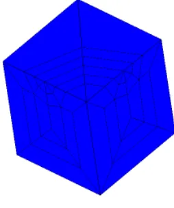
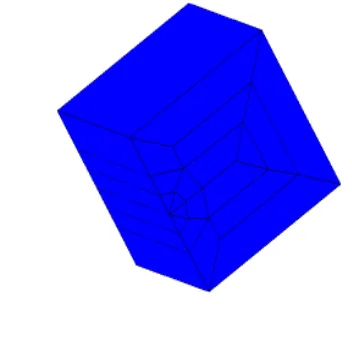
We have developed several types of crack bricks which are able to be geometrically transformed, combined and connected in order we may obtain requested crack shape and dimensions at given component location. In principle, such crack bricks are originally defined and stored as partial FE meshes which have unit cube outer shape and complicated inner structure determining a part of crack with its surroundings. Topological definition of component elements (replaced elements) and elements included in inserted crack bricks has to be identical. Some examples of such crack bricks are on Fig.2 and Fig.3.
Fig. 3 Crack brick example 2
Each node coordinates of inserted crack brick has to be calculated by means of quadratic isoparametric
shape functions N
i(
ξ
,
η
,
ζ
) :
20
x=
Σ
N
i(
ξ
,
η
,
ζ
) x
i, (1)
i
=120
y=
Σ
N
i(
ξ
,
η
,
ζ
) y
i, (2)
i
=120
z=
Σ
N
i(
ξ
,
η
,
ζ
) z
i, (3)
i
=1where
ξ
,
η
,
ζ
are corresponding local isoparametric coordinates of inserted crack brick node and x
i, y
iand z
iare
coordinates of twenty nodes of replaced element.
GiD Programme Environment Utilization
All steps contained in the procedure of crack insertion into given component FE mesh and generation of input data set for FEM programme ADINA are carried out within graphic environment of user friendly GiD computer code (version 5-academic). New “problem type” named Crack was defined which includes the elaboration of following basic files located in GiD subdirectory CRACK.GID :
1) crack.prb - the definition of calculation controlling variables 2) crack.mat - the definition of component material properties 3) crack.cnd, crack.sim - the definition of boundary condition
4) crack.bas - programme for input data generation in the format of ADINA 6.1
Besides basic files special plug-in programmes written in TCL language and C++ language were written for this problem type ensuring communication and cooperation with GiD main module :
Therefore all necessary operations are performed in a interactive way inside GiD graphical environment using menu selection and direct data input. The results of all partial steps connected with crack insertion can be seen and checked directly.
The typical sequence of steps follows : 1) running GiD
2) the definition of a new project - problem type has to be set to Crack in Data menu and saved in File menu using some proper name
3) the aplication of Crack menu - firstly we need to Read intact FE mesh, then we will Insert parts of crack
4) the other data input – control variables, boundary condition, material properties using corresponding items of Data menu 5) write ADINA input file using File menu (Import/Export choice)
Data input relating to point 3 of previous list can be illustrated on corresponding screen hardcopies : Read mesh menu
Only the name of file containing original intact FE mesh must be given
Insert crack menu
REFERENCES
1. GiD User Manual, Pre and Past Processing System for FEM calculations, version 5.0 p47, CIMNE Barcelona, 1999 2. GiD User Manual, Pre and Past Processing System for FEM calculations, version 6.0, CIMNE Barcelona, 2000 3. ADINA-Theory and Modelling Guide, ADINA R&D, Inc., 1999