Configuration of Frame Relay- A
Standardized Wide Area Network Technology
Gujarathi Thrivikram, K.K.B.Abhishek
Student, Dept. of ECE, GITAM University, Visakhapatnam , India
Student, Dept. of ECE, GITAM University, Visakhapatnam , India
ABSTRACT: In this paper, the frame relay has been configured using Cisco packet tracer.The frame-relay is nothing by a technology where the connections are made virtually due to this it is cost efficient. The configuration of it is verified by using ping command and the results are explained . Frame Relay uses a dlci number for every virtual connection .
KEYWORDS: DLCI, Cisco Packet Tracer, Frame Relay, WAN technology.
I. INTRODUCTION
Frame relay is a methodology used mainly for the voice and data transfer in WAN(Wide Area Network) and LAN (Local Area Network)connections. Its is less cost because of this usage of low equipment .It is widely used because of the simple configuration than the other networking techniques. This technique makes the data in units called ‘Frames’. It will not include any unwanted data such as retransmission of data to the end points.
II. RELATED WORKONFRAMERELAY
ISSN(Online): 2320-9801
ISSN (Print) : 2320-9798
I
nternational
J
ournal of
I
nnovative
R
esearch in
C
omputer
and
C
ommunication
E
ngineering
(An ISO 3297: 2007 Certified Organization)
Vol. 4, Issue 3, March 2016
After packet has been reached to the destination, destination will wait for time δt and collects all the packets. After time δt it calls the optimization function to select the path and send RREP. Optimization function uses the individual
node’s battery energy; if node is having low energy level then optimization function will not use that node.
III.IMPLIMENTATIONOFFRAMERELAY
In this topology the frame relay is implemented by using the three routers and a cloud , the connection between the router and cloud is using the serial port.The most important one is that here using one serial ports we are connected three routers i.e, using one serial port we are connected three routers. By this method cost has been decreased and due to increase in error handling at the ends of the destination allows this protocol to discard incorrect frames and thus increases the process to complete fast because the time consumed by the error frames has been decreased.
Figure 2: showing the connection of routers using frame relay.
The figure also explains the flow of packets from router 10 to other router connected to each other are successful.
IV.CONFIGURATIONOFFRAMERELAYUSINGCISCOPACKETTRACER
ISSN(Online): 2320-9801
ISSN (Print) : 2320-9798
I
nternational
J
ournal of
I
nnovative
R
esearch in
C
omputer
and
C
ommunication
E
ngineering
(An ISO 3297: 2007 Certified Organization)
Vol. 4, Issue 3, March 2016
Then we have to configure the router 7 as follows:
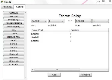
After the configuration of routers, we have to add the connections i.e the virtual links in the cloud as follows:
ISSN(Online): 2320-9801
ISSN (Print) : 2320-9798
I
nternational
J
ournal of
I
nnovative
R
esearch in
C
omputer
and
C
ommunication
E
ngineering
(An ISO 3297: 2007 Certified Organization)
Vol. 4, Issue 3, March 2016
Figure 4 : shows the adding of dlci numbers in serial 1 port.
Figure 6: shows the adding of dlci numbers in serial 3 port.
After all adding the dlci number we have to add links like the following figures: Dlci-100 (s0) to Dlci-103 (s1)
ISSN(Online): 2320-9801
ISSN (Print) : 2320-9798
I
nternational
J
ournal of
I
nnovative
R
esearch in
C
omputer
and
C
ommunication
E
ngineering
(An ISO 3297: 2007 Certified Organization)
Vol. 4, Issue 3, March 2016
In the figure the port: serial port, sublink : is the name given in the previous figures at the serial ports. We provide the reference to these connection above this figure.
V. EVALUATIONOFFRAMERELAYCONNECTION
Here, we use the pinging command to check the connection from router 10 to router7, router 8, router 9 after pinging we must get the 100% success rate need to prove that the connections are working properly.
Table1: showing the assigning of ip address, dlci, connection of serial ports.
IV.CONCLUSION
In this paper, mainly focused on the usage of frame relay concept of connecting the three routers using single router serial port. The configuration and results are explained .The software used here is ‘Cisco Packet Tracer’ for configuration and simulation of the frame-relay concept.
REFERENCES
1. ‘’Frame Relay Networks - a survey’’ by Viswanath Subramanian . 2. ‘’Cisco Frame Relay Solutions Guide 2nd edition’’ by Jonathan Chin. 3. ‘’Frame Relay: Technology and Practice 1st Edition’’ by Jeff T. Buckwalter. 4. ‘’ISDN and Broadband ISDN with Frame Relay and ATM’’ By Stallings.
Router name Ip address Serial port Dlci
Router10 10.0.0.1 2/0.2 100
Router 10 11.0.0.1 2/0.3 101
Router 10 12.0.0.1 2/0.4 102
Router 9 10.0.0.2 2/0 103
Router 7 11.0.0.2 2/0 104
BIOGRAPHY
Gujarathi Thrivikram has pursuing his bachelor of Electronics and Communication Engineering in GITAM University, Vizag. His interests on networking, wireless communication . Follow his blogspots : http://cybersolutions333.blogspot.in/ and http://howtolearnnetworking.blogspot.in/ .