78: 6–13 (2016) 129–136 | www.jurnalteknologi.utm.my | eISSN 2180–3722 |
Jurnal
Teknologi
Full Paper
FAST
AND
ROBUST
STEREO
MATCHING
ALGORITHM
FOR
OBSTACLE
DETECTION
IN
ROBOTIC
VISION
SYSTEMS
Masoud Samadi
*, Mohd Fauzi Othman, Muhamad Farihin Talib
Malaysia-Japan International Institute of Technology (MJIIT),
Universiti Teknologi Malaysia, Kuala Lumpur, Malaysia
Article history
Received
13 January 2016
Received in revised form
18 March 2016
Accepted
23 March 2016
*Corresponding author
[email protected]
Graphical abstract
Abstract
In this paper, we propose a new area-based stereo matching method by improving the classical Census transform. It is a difficult task to match the corresponding points in two images taken by stereo cameras, mostly under variant illumination and non-ideal conditions. The classic Census nonparametric transform offers some improvements in the accuracy of disparity map in these conditions but it also has some disadvantages. Because of the complexity of the algorithm, the performance is not suitable for real-time robotic systems. In order to solve this problem, this paper presents the differential transform using Maximum intensity differences of the pixel placed in the center of a defined window and the pixel in the neighborhood to reduce complexity and obtain better performance compared to the Census transform. Experimental results show that the proposed method, achieves better efficiency in terms of speed and memory consumption. Moreover, we have added a new feature to widen the depth detection range. With the help of the proposed method, robots can detect obstacles between 25cm to 400cm from robot cameras. The result shows that the method has the ability to work in a wide variety of lighting conditions, while the stereo matching performs the depth detection computation with speed of 30FPS.
Keywords: Stereo vision; obstacle detection; robotic; stereo matching; differential
transform
© 2016 Penerbit UTM Press. All rights reserved
1.0 INTRODUCTION
Nowadays, robots and computers make life better and easier for everyone. These robots use different types of sensors and actuators to perform their duty. Among these automated machines there are some vehicles which need to move around and navigate autonomously to complete their tasks. One of the crucial parts in these kinds of mobile robots which help them to navigate without any human operator present is environment perception sensors [1]. In order to perform their task, robots should have a sufficient realization of their environment to work safely within their workhouse [2]. Previously, this information was in 2D format and was not accurate enough to be used in mobile robots in important and hazardous sites. In recent years, stereo vision systems take place in
environment perception methods [3]. This method has a great ability to deliver the 3D information of every object in the robot’s field of view.
the robot, making it an acceptable choice for home applications.
However, stereo vision is not perfect yet and has problems in detecting the corresponding pixel in stereo images and is sensitive to illumination changes. Here we propose a method to overcome the mismatching problem in different lighting conditions without losing the performance of the stereo matching algorithm in terms of speed and accuracy.
2.0 RELATED WORKS
In recent years, researchers have been working on various methods to bring the 3D information of the environment that robots operate in. As a result of their work, two main categories of stereo vision algorithms have been proposed. Area-based and Feature-based are two classes of stereo matching method. A complete evaluation of several stereo matching methods can be found in the work of Hirschmuller in [5], [2].
The Area-based algorithm uses a little size window in its image to compute the disparity map. In other words, they divide a pair of images into small blocks and then compare them together. In order to find the best correspondence block in these images, Area-based algorithm gets help from other methods like the Sum of the Square Differences (SSD), Sum of the Absolute Differences (SAD) [6], normalized cross-correlation (NCC) [7] or Sum of the Hamming Distances (SHD). The disparity map generated by Area-based method is robust to illumination changes. Although this algorithm provides dense and smooth disparity map, the block by block comparison procedure consumes a lot of system resources and time. Thus, it is regarded as a slow algorithm.
On the other hand, the Feature-based method is fast and needs a small amount of system resources to generate the depth map. This characteristic makes the Feature-based algorithm an appropriate method for robots and real-time systems such as that mentioned in P. Ben-Tzvi et al. [8]. However, although the calculation speed in this method is faster than the Area-based algorithm, the results are sparse and suffer from low accuracy and high error rate. The disparity map generates only areas with special features to detect and compare. The textureless regions or low texture objects will either not be detected at all or just some part of them will be detected.
Thus, some researchers tried to use the combination of different sensors on behalf of a stereo vision. In [9], B.H. Schafer et al. used very expensive laser range finder to boost the stereo vision method. This laser range finder leads to an increase in the cost of the robot, therefore it is not widely accepted among robot designers. B. Khaleghi in [10] used the Census transformation method which was introduced by Zabih and Woodfill in [11] on a FPGA platform, which shows a good result in reducing the effects of variations caused by camera gain and bias, and
showing more resistance to illumination changes. Census is a non-parametric local transform which looks for a certain relation between image pixels in a defined window. Nonparametric transforms have a good ability to reduce the effect of noises on images and achieve good results in various test conditions.
Census transform obtains its result with a bit-wise calculation and compared to previous methods which only use one pixel value to perform the operation, has more efficient and accurate results and a great capability to be used in robotic systems because of its robustness to illumination changes. This particular feature makes Census efficient in different kinds of environments.
Equations (1) and (2) explain the Census transform formula that uses intensity relation between the pixel in the center and neighbor pixels in a defined window size:
𝜉(𝑝1, 𝑝2) = {0 𝑝1 𝑝1< 𝑝2 1> 𝑝2
(1)
𝑝1 denotes the pixel located at the center of the
window while adjacent pixels are shown by 𝑝2. If the
intensity value of 𝑝1 is more than its neighbor pixel
𝑝2the value of 𝜉 for that specific pixel will be 1, and if it
is less than the neighbor pixel it will be set as 0. The equation in (2) describes how the Census value for the center pixel of the defined window is calculated:
𝐼𝑐𝑒𝑛𝑠𝑢𝑠(𝑢, 𝑣) = ⊗𝑖=𝑛⊗𝑗=𝑚(𝜉(𝐼(𝑢, 𝑣), 𝐼(𝑢 + 𝑖, 𝑣
+ 𝑗)))
(2)
Operator ⊗ denotes a bit-wise concatenation, where
𝑛 × 𝑚 is the window’s size and 𝑢, 𝑣 are pixel
coordinates.𝐼𝑑𝑖𝑓𝑓 denotes the maximum differences
between the center pixel of an 𝑚 × 𝑛 window and all of the neighboring pixels. One of the most important drawbacks in this method is in its long computation time. In order to reduce the number of comparisons, Zabih proposed the Sparse Census transform. This method avoids the twice calculation for one pixel by defining a certain space. One of the best ways to increase the speed of stereo matching function is to change the Census method with a faster one. Therefore, In order to achieve better performance we use a new method which is called the Differential Transform. In the next section, the Differential algorithm is explained and our solution to increase the detection range is described.
3.0 STEREO MATCHING ALGORITHM
step, images are put through undistortion function to correct the lens distortion and rectify them by using the calibration matrix that was mentioned in the previous stage [12]. More explanation about image rectification and camera calibration can be found in [16]. Next, the pair of images is ready for further stereo matching process. In previous methods, the rectified images are transformed to an 8 bit images by means of the Census method before computing the initial three dimensional image.
In order to increase the performance of stereo vision algorithm mentioned before, we use a different method to compute the disparity map which is called Differential Transform. This transform is a non-parametric algorithm that inherits some of the Census method characteristic such as robustness to illumination changes and has the ability to work in different kinds of environment. Although this method reduces the effect of noise and camera bias just like Census, it works faster than the previous works. The aforesaid method helps the robot to find out the distances between the robot and object in the field with the speed of 30FPS which is necessary for immediate actions of mobile robots.
Here, we use our proposed method which we call Differential Transform instead of the Census method, to obtain 8 bit transformed images. A complete description of our proposed method will be explained in the next part. In order to increase the speed performance of image transform and reduce the computation cost, we change the Census equation
and reduce the number of comparisons, so the complexity of the code is decreased and the program is executed with more speed than the old Census transform method. Thus, in order to increase performance, we use Equation 3.
𝜁(𝑝1, 𝑝2) = |𝑝1− 𝑝2| (3)
The result 𝜁 is the absolute difference between the center pixel of the Census window and the neighborhood pixels. Equation (2) is reformulated as shown in (4).
𝐼𝑑𝑖𝑓𝑓(𝑢, 𝑣) = max
𝑖= −𝑛2𝑗= − max𝑚2(𝜁(𝐼(𝑢, 𝑣), 𝐼(𝑢 + 𝑖, 𝑣 + 𝑗)))
(4)
𝐼𝑑𝑖𝑓𝑓 denotes the maximum differences between the
center pixel of an 𝑚 × 𝑛 window and all of the neighboring pixels. Because the image is processed in the grayscale format, the maximum intensity difference between the two pixels can be 255. Therefore, the transformed matrix can be saved as an 8-bit image and is independent of the window size, while the size of the Census transformed matrix depends on the size of the window size. These modifications and changes result in a faster processing rate and less memory resources are required by the algorithm because it has reduced the transformed image size to 8-bit instead of depending on the window size which is normally defined as 16 pixels.
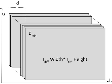
The results of the last step, so called Differential transform, are needed to produce the three-dimensional matrix. This matrix, which is called disparity space image (DSI), is generated with the size of
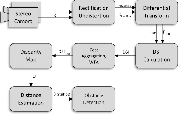
Figure 1 The workflow of the proposed algorithm
𝑛𝑢𝑚𝑏𝑒𝑟 𝑜𝑓 𝑑𝑖𝑠𝑝𝑎𝑟𝑖𝑡𝑦 × 𝑖𝑚𝑎𝑔𝑒 𝑠𝑖𝑧𝑒. DSI is created by
computing the hamming distance between the transformed images as shown in the formula:
𝐷𝑆𝐼𝐿(𝑢, 𝑣) = 𝐻𝑎𝑚𝑚𝑖𝑛𝑔 (𝐿𝑑𝑖𝑓𝑓(𝑢, 𝑣), 𝑅𝑑𝑖𝑓𝑓(𝑢
− 𝑑, 𝑣))
(5)
DSI is computed when the right image is shifted horizontally from right to left (Figure 2), and the left image is used as the reference. The shifting distance is
defined by d in Equation 5 and this value is called the disparity value. In fact, this is the furthest range which the stereo vision system can calculate.
Rectification Undistortion
Differential Transform Stereo
Camera eo
DSI Calculation Disparity
Map
Cost Aggregation,
WTA
Distance Estimation
Obstacle Detection R
L LRectified
RRectified
LDiff R
Diff
DSI DSIAggr
D
Figure 2 The three-dimensional data called Disparity space
image (DSI) in the size of disparities * image size
After applying the cost aggregation and a simple winner take all, the initial disparity map is ready to generate. By our experiment and as mentioned in [13], [14],[15] the best result of Census transforms are achieved with 16x16 window size, while the proposed algorithm can achieve the best accuracy with 5x5 window. This special feature reduces the large window size overloaded on the processor unit and decreases the calculation time. After computing the initial disparity map, we implement a method to increase the depth detection range of the stereo matching function.
One of the defects of stereo vision systems is in its minimum detection range which is normally only 60cm. Even Kinect sensor that is released by Microsoft, has a limitation of 60cm. In some mobile robots, it is necessary for the robot to see the objects that are close to it, to avoid collision. Thus, an additional sensor can help the stereo vision to prevent such problems. As we have tried to use a pure stereo vision system without any combination of other sensors, we propose a solution to overcome this issue and increase the depth detection range, such as lowering the minimum detection limit. The stereo matching algorithm range depends on different parameters, such as:
•The horizontal Distance between two cameras •The angle between two cameras
•Stereo cameras Calibration (Distortion Coefficient) •Software horizontal image shifting
The first two parameters depend on stereo cameras hardware, and they need mechanical actuators to adjust them. The other parameters can be changed just by software programming and has no need for any additional motors or actuators. To avoid the extra cost for our stereo vision system, and to make the adjustment easy to apply, we use software parameters to increase the depth range. In the software horizontal image shifting mode, if we move one image horizontally towards the other one, the
minimum detection limit for the stereo vision will reduce.
Figure 3 shows a clearer picture. For example, if the system could detect distances more than 70cm in normal mode, by using this method it will detect distances more than 25cm. But the drawback of this method is that the maximum detection range will reduce. Therefore, to overcome this problem, we calculate the disparity map twice, one to detect distances between 70cm to 400cm, and the other for range of 25cm to 70cm. The disparity maps are then matched. As a result of this method, the robot could detect very near objects to it.
Figure 3 Depth detection range in: a) Normal Stereo
matching, b) After shifting one of the stereo Images
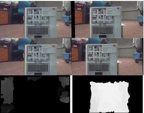
This solution is really useful in avoiding collision. It reduces the calculation speed because of computing disparity map twice. We put some conditions to activate this part of the code to prevent reducing the execution speed of the program. Since closer objects to the robot cover a large number of pixels in pairs of images, and as its out of detection range is in normal mode, a high percentage of the first disparity map will be black. Therefore, the program can understand that there is a need to run the second disparity map code to detect the distance to the closer object. The robot cameras are installed at the back of the robot’s body, hence there is no need to detect objects closer than 25cm. Although shifting images towards each other leads to losing data in the very edge of the images, using a wide angle camera solves this issue. Objects located at the edge of the wide images are far away from the robot and will not interfere with the robot path. By using this method, the need of additional sensors is resolved. Figure 4 shows the result of image shifting and how it helps to detect objects that are close to the robots.
The displacement distance presented between the left and right cameras are projected as pixel values in disparity map image. The objects closer to the camera show more displacement distance between the left and right images. These objects are demonstrated by higher value in disparity which results in lighter colour in the disparity map. On the other hand, further objects are shown by darker colours.
d
mind
d
mind
d
d
mind
d
mind
d
mind
d
minI
diffWidth* I
diffHeight
d
Left Image Right Image a)
70cm 400cm
Depth Detection Range
Left Image Right Image b)
25cm 70cm
Figure 4 At the top pair of images captured by stereo
cameras and at the bottom their related disparity after and before shifting images
Thus, by finding an equation between the pixel density value in the disparity map and distance, we can define the coordination of each object in the field. In this stage, the result of the stereo matching function is ready, so by using a mathematics formula we estimate the distance between the robot cameras and other objects. Figure 5 shows the relation between distance in cm and the disparity map pixel density values. With the help of this diagram, we extract a mathematics equation to convert the disparity values to distances as shown in Equation 6.
𝐷𝑖𝑠𝑡𝑎𝑛𝑐𝑒[𝑥, 𝑦] = −101.5 ∗ 𝑙𝑛(𝐷𝑖𝑠𝑝𝑎𝑟𝑖𝑡𝑦[𝑥, 𝑦])
+ 586.3 (6)
Figure 5 Distance estimation by using the Disparity map
This equation generates the depth value of a point with coordinate [𝑥, 𝑦] by using the disparity map pixel
[𝑥, 𝑦] density value. The result is in ‘cm’ and used in the
obstacle detection part of the robot program. Hence the obstacle detection function can calculate the exact location of each object in 3D and by calculating the location and dimension of an obstacle, it can prevent the collision between the robot and other objects in the environment.
4.0 RESULTS AND DISCUSSION
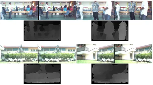
The results of our experiments in a real world test, show that our proposed method has the capability to run at more than 30FPS. It has resistance to illumination changes which means the robot can operate in different kinds of environment and is compatible for indoor and outdoor use. Figure 6 demonstrates the disparity map computed by the robot on the stereo vision function in a non-ideal condition. As mentioned before, the robot could detect objects in the range of 25cm to 400cm from the robot’s cameras. Thus, the solo stereo vision is enough for the robot to perform the task, without the need of any additional sensor.
The proposed method is evaluated using a popular benchmark database. The Middlebury dataset is used as a benchmark database for assessing and analyzing the proposed stereo vision technique [18]. The proposed method, Census, Rank and Census Sparse have been tested on the Middlebury stereo vision dataset (Figure 7) and the results show that this method gained better execution speed compared to other methods. As a result of our experiments, it is clear that the proposed method needs a smaller window size to achieve the best accuracy in comparison to other algorithms. Thus, the executing speed of the algorithm increases and the time to calculate the disparity map reduces. The proposed method also inherits some particular features of Census transform such as being robust to different luminance conditions, and has the ability to reduce effects of camera gain and bias, as shown in Figure 8. From our experiment and as mentioned in [15], [17] the best result of Census transforms are achieved with 16x16 window size, while the proposed algorithm can achieve the best accuracy with 5x5 window. This particular feature can reduce the large window size overloaded on the processor unit and decrease the calculation time. The time consumed by each method and their error rates are demonstrated in Table 1.
0 50 100 150 200 250 300 350 400 450
0 100 200 300
D
istan
ce
(c
m
)
Table 1 Speed and accuracy comparison on the middlebury dataset
Dataset Methods
Proposed Method census census sparse Rank
time Tsukuba 0.00542 0.12891 0.02683 0.07890
Cones 0.00803 0.43985 0.07734 0.17412
Teddy 0.00790 0.31196 0.08282 0.16543
Venus 0.00732 0.28534 0.28534 0.08445
Error rate Tsukuba 10.67 11.39 10.27 11.99
Cones 15.18 15.68 15.04 16.22
Teddy 16.55 16.46 17.24 16.74
Venus 5.78 5.07 4.75 6.22
Figure 6 At the top, the pair images captured by robot stereo cameras, at the bottom, the disparity map calculated by the
proposed algorithm after noise removal and edge normalization in non-ideal outdoor and indoor lighting conditions
Figure 7 Comparison of the disparity map of the Middlebury dataset (Cones, Teddy, Tsukuba,Venus). From left to right (First row):
Figure 8 Comparison of the disparity map of the Middlebury dataset (Cones, Teddy, Tsukuba,Venus). From left to right (First row):
Left Stereo image and its local ground truth disparity map, SAD, Census, (Second row): Census Sparse, Rank, Rank Sparse, Proposed Method.
5.0 CONCLUSION
In this work, we deal with the stereo matching speed problem. Our research lies its attention on non-parametric image transform methods to gain robustness of the stereo matching algorithm in different lighting conditions without losing the execution speed of the program. To achieve this goal we reformulate the old Census transform method and are able to gain better performance in computing the disparity map compared to previous works. This method can be implemented in real-time stereo vision which is used in robotic applications. In future work, the proposed method will be implemented on a stereo vision-based robot which uses Intel x86 CPU architecture, since the code has already been developed in C++ language. Under Visual Studio 2010 Environment, the program can be executed on the mentioned platform to analyze the robot behavior in a real world experiment.
Acknowledgement
We would like to thank the Center for Artificial Intelligence and Robotics (CAIRO), Malaysia-Japan International Institute of Technology (MJIIT), Universiti Teknologi Malaysia (UTM) and Ministry of Higher Education (MOHE) for providing the research facilities. This research work has been supported by grant No. VOT 00G20. The support and guidance given by the aforesaid parties are deeply appreciated.
References
[1] J. Calderon, A. Obando, and D. Jaimes. 2007. Road Detection Algorithm For An Autonomous Ugv Based On Monocular Vision. Electronics, Robotics and Automotive Mechanics Conference, 2007. CERMA 2007. Sept 2007. 253–259.
[2] M. Brown, D. Burschka, and G. Hager. 2003. Advances in computational stereo. Pattern Analysis and Machine Intelligence, IEEE Transactions on. Aug 2003. 25(8): 993– 1008.
[3] D. Scharstein and R. Szeliski. 2001. A Taxonomy And Evaluation Of Dense Two-Frame Stereo Correspondence Algorithms. International Journal Of Computer Vision. 47: 7–42.
[4] S. M. Grigorescu, G. Macesanu, T. T. Cocias, D. Puiu, and F. Moldoveanu. 2011. Robust Camera Pose And Scene Structure Analysis For Service Robotics. Robotics and
Autonomous Systems. 59(11): 899–909.
[5] H. Hirschmuller and D. Scharstein. 2009. Evaluation Of Stereo Matching Costs On Images With Radiometric Differences. Pattern Analysis and Machine Intelligence. IEEE Transactions on. Sept 2009. 31(9): 1582–1599.
[6] T. Kanade, H. Kano, S. Kimura, A. Yoshida, and K. Oda. 1995. Development of a video-rate stereo machine. In Intelligent Robots and Systems 95. Human Robot Interaction and
Cooperative Robots. Proceedings. 1995 IEEE/RSJ
International Conference on. Aug 1995. 3.
[7] M. J. Hannah. 1974. Computer Matching Of Areas In Stereo Images. Ph.D. dissertation, Stanford, CA, USA.
[8] P. Ben-Tzvi and X. Xin. 2010. An Embedded Feature-Based Stereo Vision System For Autonomous Mobile Robots. In Robotic and Sensors Environments (ROSE), 2010 IEEE International Workshop on. 1–6.
[9] B. H. Schfer, M. Proetzsch, and K. Berns. 2005. Stereo-Vision-Based Obstacle Avoidance In Rough Outdoor Terrain. International Symposium on Motor Control and Robotics. [10] B. Khaleghi, S. Ahuja, and Q. Wu. 2008. An Improved Real-Time Miniaturized Embedded Stereo Vision System (mesvs-ii). In Computer Vision and Pattern Recognition Workshops, CVPRW ’08. IEEE Computer Society Conference on. 1–8. [11] R. Zabih and J. Woodfill. 1994. Non-Parametric Local
Transforms For Computing Visual Correspondence. In Proceedings of the Third European Conference-Volume II on Computer Vision - Volume II, ser. ECCV ’94. UK: Springer-Verlag. 151–158.
[12] Fusiello, E. Trucco, and A. Verri. 2000. A Compact Algorithm For Rectification Of Stereo Pairs. Mach. Vision Appl.12(1): 16–22.
[13] Zinner, M. Humenberger, K. Ambrosch, and W. Kubinger. 2008. An Optimized Software-Based Implementation of a Census-Based Stereo Matching Algorithm, ser. Lecture
Notes in Computer Science. 5358: 216–227.
Workshops (ICCV Workshops). IEEE 12th International Conference on. 786–793.
[15] V. Ganapathy and O.-E. Ng. 2008. Stereo vision based robot controller. In Systems, Man and Cybernetics, 2008. SMC 2008. IEEE International Conference on. 1849–1854. [16] M. Samadi, M. F. Othman and SH. H. M. Amin. 2013. Stereo
Vision Based Robots: Fast and Robust Obstacle Detection Method. The 9th Asian Control Conference (ASCC 2013). June 2013.
[17] Samadi, M. and M. Othman. 2013. A New Fast and Robust Stereo Matching Algorithm for Robotic Systems. The 9th International Conference on Computing and Information Technology (IC2IT2013). In P. Meesad, H. Unger, and S. Boonkrong (Ed). Springer Berlin Heidelberg. 281-290. [18] Middlebury. 2012. The Middlebury Stereo Evaluation