DEVELOPMENT AND VALIDATION OF A BOND SLIP MODEL FOR
THE SIMULATION OF INDUSTRIAL STRUCTURES
A. Casanova1, 2, L. Jason1, 3, L. Davenne4
1 CEA, DEN, DANS, DM2S, SEMT, LM2S, F-91191 Gif sur Yvette, France
2 Laboratoire de Mécanique et Technologie (LMT), ENS Cachan, F-94235, Cachan, France 3 LAMSID, UMR CNRS-EDF-CEA 2832, F-92141 Clamart, France
4
IUT de Ville d’Avray, F-92410 Ville d’Avray, France
ABSTRACT
This paper presents a new finite element approach to model the steel-concrete bond effects. This model proposes to relate steel, represented by truss elements, with the surrounding concrete in the case where the two meshes are not necessary coincident. The theoretical formulation is described and the model is applied on a reinforced concrete tie. A characteristic stress distribution is observed, related to the transfer of bond forces from steel to concrete. The results of this simulation are compared with a computation in which a perfect relation between steel and concrete is supposed. It clearly shows how the introduction of the bond effects can improve the description of the cracking process (crack spacing especially).
INTRODUCTION
Reinforced concrete structures may have to fulfill functions that go beyond their simple mechanical resistance. In some cases, information about the cracking behavior may also become essential. For example, in the case of containment buildings for nuclear power plants, cracking has a direct impact on the transfer properties that govern the potential leakage rate. Predicting the mechanical behavior but also characterizing the crack evolution (opening and spacing) are thus key points in the evaluation of this type of reinforced concrete structures.
Cracking in reinforced concrete structures is generally influenced by the stress distribution along the interface between steel and concrete [1]. Taking into account these effects seems thus essential to predict correctly the cracking evolution. Different models exist to represent the steel-concrete bond behavior. For example, Ngo and Scordelis [2] proposed a spring element to relate concrete and steel nodes. To improve the description of the bond behavior, joint elements were developed ([3], [4], [5], [6], [7] and [8]). Finally, special finite elements can be proposed to enclose, in a same element, the material behavior (steel or/and concrete) and the bond effects ([6], [7] and [9]). Even if these solutions give appropriate results, one of their main drawbacks is the need to explicitly consider the interface between steel and concrete. It may impose meshing difficulties and heavy computational cost which are not compatible with large scale simulations. To overcome these difficulties, a perfect relation between steel and concrete is generally considered for structural applications and the reinforcement is modeled using truss elements. This hypothesis imposes the same strain in both materials. This approach simplifies the simulation but it cannot represent stresses transfer induced by the steel concrete bond.
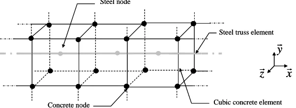
In this contribution, a model is proposed to combine the advantages of the two approaches. It is able to represent the bond effects (the evolution of the slip between steel and concrete especially) and is appropriate for structural applications (mesh and computational cost). The general configuration is to consider steel truss elements and concrete (1D, 2D or 3D elements) in the case where steel and concrete nodes are not necessary coincident (Fig. 1)
Concrete node
Steel node
Cubic concrete element Steel truss element
x
r
y
r
z
r
Concrete node
Steel node
Cubic concrete element Steel truss element
x
r
y
r
z
r
x
r
y
r
z
r
Fig. 1 : Description of the problem (steel and concrete nodes are not coincident)
DESCRIPTION OF THE BOND MODEL
In reinforced concrete structures, the relation between steel and concrete is governed by a bond stress distributed along the interface which is generally studied in the form of a bond stress τ -relative displacement s (slip between steel and concrete) law f defined in equation (1). b
) (s fb
=
τ (1)
The principle of our approach is to introduce internal forces on both steel and concrete in the direction of the steel truss element. As concrete and steel nodes are not necessary coincident, each steel node is thus associated with the concrete element in witch it is included and with a tangential direction tr .
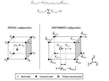
In this contribution, equations will be developed in the particular case of a unique steel node inside a cubic concrete element as illustrated in Fig. 2 (initial configuration). In order to simplify the equations, trcoincides with the principal direction xr.
Evaluation of the relative displacement between steel and concrete
The steel-concrete slip s is represented by the relative displacement in the x direction between the steel (urs1 at node
s
1) and the concrete at the steel node (urcs1 at virtual point cs ) (Fig. 2). 1x cs x
s u
u
s= 1, − 1, (2)
with us x us x r r
⋅
= 1
,
1 and ucs x ucs x
r r
⋅
= 1
,
1 .
As the meshes are not necessary coincident, the displacement in concrete at the steel node is obtained using the shape functions, following the equation:
∑
== 8
1
, 1 1 1 ,
1 ( , , )
i
x ci cs cs cs i x
cs N x y z u
u (3)
where(xcs1,ycs1,zcs1) are the coordinates of cs point. 1 Ni(xcs1,ycs1,zcs1)represents the shape function of the i-th concrete node evaluated at cs point and 1 uci,x its displacement in the x
r
direction.
Nodal forces in the tangential direction
From equations (1), (2) and (3), internal nodal force induced by concrete on steel Fcs1 s/1 r
is calculated using the equation:
(
u u)
xf l d x s l d
Fcs s s r s b s x cs r
r
⋅ − =
⋅
= 1, 1
1 /
1 δπ τ( ) δπ *
with
< − −
=
≥ − =
0 1
0 1
1 , 1
1 , 1
cs x s
cs x s
u u if
u u if
δ
δ (4)
For the internal forces applied on concrete, the balance involves 8 nodal equivalent forces Fs1/cj r
applied on each concrete node (Fig. 3).
1 / 1 1 1 1 /
1cj j( cs, cs , cs ) cs s
s N x y z F
F r r − = (5) So as 0 / 1 1 /
1 +
∑
=j cj s s cs F F r r (6)
x
r
y
r
z
r
x cu
7,r
INITIAL configuration
c
1c
2c
3
c
4c
5c
6c
8c
7cs
1s
1x c
u
2,r
x c
u
3,r
x c
u
r
5,u
r
c8,x x cu
r
4, DEFORMED configurationx c
u
1,r
x c
u 4,
r
x c
u 6,
r
x c
u
6,r
x c
u
4,r
x c
u
1,r
x s
u
1,r
x cs
u
1,r
x cs x su
u
s
=
1,−
1,Concrete node
Steel node Virtual concrete point
≡
x
r
y
r
z
r
x cu
7,r
INITIAL configuration
c
1c
2c
3
c
4c
5c
6c
8c
7cs
1s
1x c
u
2,r
x c
u
3,r
x c
u
r
5,u
r
c8,x x cu
r
4, DEFORMED configurationx c
u
1,r
x c
u 4,
r
x c
u 6,
r
x c
u
6,r
x c
u
4,r
x c
u
1,r
x s
u
1,r
x cs
u
1,r
x cs x su
u
s
=
1,−
1,x
r
y
r
z
r
x
r
y
r
z
r
x cu
7,r
INITIAL configuration
c
1c
2c
3
c
4c
5c
6c
8c
7cs
1s
1x c
u
2,r
x c
u
3,r
x c
u
r
5,u
r
c8,x x cu
r
4, DEFORMED configurationx c
u
1,r
x c
u 4,
r
x c
u 6,
r
x c
u
6,r
x c
u
4,r
x c
u
1,r
x s
u
1,r
x cs
u
1,r
x cs x su
u
s
=
1,−
1,Concrete node
Steel node Concrete node Virtual concrete point
Steel node Virtual concrete point
≡
Fig. 2 : Evaluation of the relative displacement between steel and concrete
Concrete node
Steel node Virtual concrete point
x c
u
r
4,x c
u
r
6,1 / 1 s cs
F
r
−
F
cs1 s/ 1r
x c
u
4,r
x c
u
6,r
Balance of the internal bond forces Equivalent nodal forces
1 / 1 s cs
F
r
1 / 1 c sF
r
2 / 1 c sF
r
3 / 1 c sF
r
4 / 1 c sF
r
5 / 1 c sF
r
6 / 1 c sF
r
7 / 1 c sF
r
8 / 1 c sF
r
(
)
8 .. 1 , , 1 1 1 = j z y xNj cs cs cs
Concrete node
Steel node Concrete node Virtual concrete point
Steel node Virtual concrete point
x c
u
r
4,x c
u
r
6,1 / 1 s cs
F
r
−
F
cs1 s/ 1r
x c
u
4,r
x c
u
6,r
Balance of the internal bond forces Equivalent nodal forces
1 / 1 s cs
F
r
1 / 1 c sF
r
2 / 1 c sF
r
3 / 1 c sF
r
4 / 1 c sF
r
5 / 1 c sF
r
6 / 1 c sF
r
7 / 1 c sF
r
8 / 1 c sF
r
(
)
8 .. 1 , , 1 1 1 = j z y xNj cs cs cs
Fig. 3 : Representation of the internal bond forces
Kinematics relations in the normal directions
= =
= =
∑
∑
= =
8
1
, 1 1 1 ,
1 , 1
8
1
, 1 1 1 ,
1 , 1
) , , (
) , , (
i
z ci cs cs cs i z
cs z s
i
y ci cs cs cs i y
cs y s
u z y x N u
u
u z y x N u
u
(7)
The model was implemented using the finite element code Cast3M [10].
VALIDATION AND APPLICATION OF THE BOND MODEL
In this part, the model is applied on a uniaxial problem. A reinforced concrete tie is studied in order to evaluate the influence of the bond effects on the mechanical behavior.
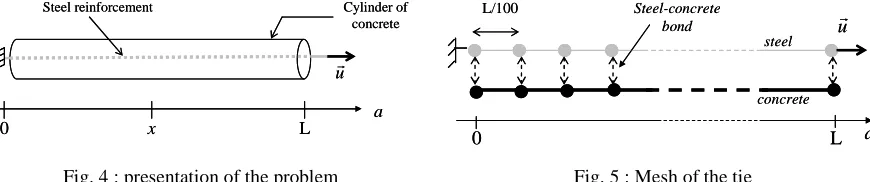
Presentation of the problem
A concrete cylinder reinforced with a longitudinal steel bar is considered. A displacement is imposed at the first end of the steel reinforcement while the other end is blocked (Fig. 4). There are no boundary conditions on the concrete.
0 x L
ur
a
Cylinder of concrete Steel reinforcement
0 x L
ur
a
Cylinder of concrete Steel reinforcement
steel
concrete ur
L 0
L/100 Steel-concrete
bond
a steel
concrete ur
L 0
L/100 Steel-concrete
bond
a Fig. 4 : presentation of the problem Fig. 5 : Mesh of the tie
For the simulation, concrete and steel are meshed by truss elements. The total length L (equal to 3 meters) is divided into 100 identical trusses as illustrated in Fig. 5. The steel behavior is modeled by a perfect plastic law (Young modulusE equal to 210 GPa, yield strength s σsstequal to 400 MPa, cross section equal to 78,54 mm2 ). Concrete is represented by a softening law, using an isotropic plastic model illustrated on Fig. 6 (Table 1). To represent the heterogeneity of concrete properties and in order to localize the mechanical degradation, a scattered distribution of the tensile concrete strength σcst is chosen. Fig. 7 represents the evolution σcst along concrete (from x = 0 to x = 3m). The average strength σc ,stmed is equal to 2 MPa and the standard deviationσy is equal to 0.03*σcst,med . The bond stress-slip law is represented by a linear function (
τ
=
k
b*
s
wherek
b is equal to 1010 Pa.m-1).
c
E (GPa) S (mc
2
) εu
30 10-2 0.045%
Table 1 : Concrete parameters (
S
cis the cross section of concrete)Global mechanical behavior
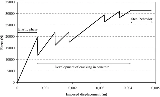
Fig. 8 represents the global behavior of the tie. This curve can be divided in 3 parts: - An elastic phase where the behavior of both materials remains linear
- A phase of concrete cracking which is characterized by several peaks and drops of force
- A perfect plastic phase where the behavior is only governed by the steel plastic law (constant force)
It is to be noted that these 3 phases are representative of the experimental behavior of reinforced concrete ties ([11] for example).
Strain Stress
st c
σ
σ
ε
c
E
u
ε
StrainStress
st c
σ
σ
ε
c
E
u
ε
1,8 1,9 2,0 2,1 2,2
0 0,5 1 1,5 2 2,5 3
x (m)
C
o
n
cre
te
S
tre
n
g
th
(M
P
a)
Fig. 6 : Form of the softening concrete law Fig. 7 : Distribution of the strength values along the tie
0 5000 10000 15000 20000 25000 30000 35000
0 0,001 0,002 0,003 0,004 0,005
Imposed displacement (m)
F
o
rc
e
(N
)
Elastic phase
Development of cracking in concrete
Steel behavior
Fig. 8 : Force-displacement curve
Elastic phase
Fig. 9 represents an example of stress distribution in both materials along the tie during the elastic phase. As the loading is applied directly on the reinforcement, at each end the force is essentially supported by the steel
(
S s
S F
≈
σ with σs the steel stress and F the applied load). Then, in a transition zone, forces are gradually
transferred from steel to concrete through the interface. Finally, in the central zone, stresses are homogeneous. It is to be noted that an analytical validation has been performed and validate the implementation of the model (not represented here).
Cracking process
a softening law. It could be solved by including a regularization technique ([11] or [12]). This point will not be discussed in this paper.
0,00E+00 2,00E+05 4,00E+05 6,00E+05 8,00E+05 1,00E+06 1,20E+06 1,40E+06 1,60E+06 1,80E+06 2,00E+06
0 0,5 1 1,5 2 2,5 3
x (m)
C
o
n
cr
et
e
st
re
ss
(
P
a
)
0,00E+00 5,00E+07 1,00E+08 1,50E+08 2,00E+08 2,50E+08
S
te
el
s
tr
es
s
(P
a
)
concrete steel
Fig. 9 : Distribution of the stress along the tie (elastic phase)
0,00E+00 5,00E+05 1,00E+06 1,50E+06 2,00E+06 2,50E+06
0 0,5 1 1,5 2 2,5 3
x (m)
S
tres
s
(P
a
)
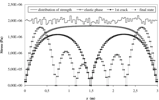
distribution of strength elastic phase 1st crack final state
Fig. 10 : Distribution of the stress in the concrete along the tie for different phases of behavior
It is to be noted that the crack position is governed, as expected, by the tensile strength distribution (Fig. 7) but also by the stress evolution imposed by the bond effects. 10 computations were also carried out considering 10 different distributions of the initial concrete tensile strength. In most cases, 5 cracks were observed. Due to the transfer zone between steel and concrete, no crack developed at both ends. Finally, the crack spacing was constant with an average value of about 50 cm. As a conclusion, the order of crack apparition is rather governed by the distribution of the mechanical strength whereas the final state (constant average spacing) is imposed by the stress distribution related to the bond effects.
INFLUENCE OF THE BOND MODEL
identical). It is this hypothesis which is generally used for structural applications. The simulation is carried out in the same conditions as described in the previous section. The only difference concerns the bond model. The global behavior (not represented here) is once again divided in 3 main phases (elastic phase, development of cracking and plastic zone).
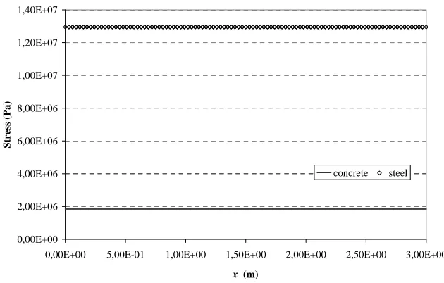
Fig. 11 describes the distribution of stress in both materials during the elastic phase. Contrary to what was observed with the bond model, stresses in steel and concrete are homogeneous along the tie.
Stresses increase in the concrete with the load until the minimal value of the concrete tensile strength is reached. A crack appears in the correspondent element. In the uncracked zone, the stress can increase until the second concrete tensile strength. Contrary to what was observed with the bond model, the apparition of the cracks is thus only governed by the strength distribution (Fig. 12). At the final state (Fig. 12), concrete is totally cracked. The loading is then only supported by steel.
As expected, the perfect relation is thus not able to represent the experimental situation where a finite number of cracks is observed [11]. The introduction of the bond effects, as presented in the previous section, solves this problem.
0,00E+00 2,00E+06 4,00E+06 6,00E+06 8,00E+06 1,00E+07 1,20E+07 1,40E+07
0,00E+00 5,00E-01 1,00E+00 1,50E+00 2,00E+00 2,50E+00 3,00E+00
x (m)
S
tr
es
s
(P
a
)
concrete steel
Fig. 11 : Stress distribution in both materials along the tie (elastic phase)
0,00E+00 5,00E+05 1,00E+06 1,50E+06 2,00E+06 2,50E+06
0 0,5 1 1,5 2 2,5 3
x (m)
S
tres
s
(P
a
)
strength distribution third crack apparition (bond model) third crack apparition (perfect relation) final state (perfect relation)
CONCLUSIONS
In this contribution, a new finite element model was proposed to represent bond effects between steel, modeled with truss elements, and the surrounding concrete. These bond effects are taken into account through additional internal forces calculated from the steel-concrete slip. The proposed model has been applied on a reinforced concrete tie. A characteristic stress distribution has been observed, related to the transfer of bond forces from steel to concrete. In this case, crack apparition is both induced by the heterogeneous characteristics of concrete (distribution of the tensile strength along the tie) and by the transition zones where stresses are redistributed between the materials. At the end of the simulation where the mechanical behavior is only governed by the steel plastic law, a finite number of crack is observed which corresponds qualitatively to experimental observations.
Another simulation, using the hypothesis of a perfect relation between steel and concrete (classical hypothesis used in structural applications), has been also proposed. In this case, the evolution of cracking is only governed by the distribution of the concrete strength since the stresses distribution is homogeneous in uncracked zones. At the final state, the concrete is totally cracked.
This example shows how the introduction of the bond model can improve the description of the cracking process. Forthcoming 3D simulations will allow to also evaluate the effects of the stress distribution in the concrete cross section.
Moreover, the crack evolution is also strongly related to the choice of the bond stress-slip law which has a direct influence on the final number of cracks. To take this influence into account, an investigation on the bond stress – slip law will thus be launched, based either on literature [13] or on an experimental campaign to be more representative of the experimental behavior.
REFERENCES
[1] Eurocode 2. Calcul des Structures en béton, NF-EN-1992, 2007
[2] Ngo D., Scordelis A.C. “Finite Element Analysis of Reinforced Concrete Beams”, ACI Journal, vol 64, March 1967, pp.152-163.
[3] Clément J.L. “Interface acier-béton et comportement des structures en béton armé - Caractérisation- Modélisation”, Thèse de doctorat de l’université Paris 6, 1987.
[4] Daoud A. “Etude expérimentale de la liaison entre l’acier et le béton autoplaçant - Contribution à la modélisation”, Thèse de doctorat de l’INSA de Toulouse, 2003.
[5] Lowes L.N., Moehle J.P., Govindjee S. “Concrete-Steel Bond Model for Use in Finite Element Modeling of Reinforced Concrete Structures”, ACI Structural Journal, vol 101, July-August 2004, pp. 501-511
[6] Dominguez N. “Etude de la liaison Acier-Béton : De la modélisation du phénomène à la formulation d’un Elément Fini Enrichi « Béton Armé »”, Thèse de doctorat de l’ENS de Cachan, 2005
[7] Boulkertous A. “Interaction feu/Ouvrage en béton armé dans le cas d’un incendie confiné : prédiction de la fissuration. Application de la problématique à des installations nucléaires” , Thèse de doctorat de l’ENS Cachan, 2009
[8] Richard B., Ragueneau F., Cremona C., Adélaide L., Tailhan J-L. “A Three-dimensional steel/concrete interface model including corrosion effects”, Engineering Fracture mechanics, vol 77, April 2010, pp 951-973
[9] Monti G., Filippou F.C., Spacone E. “Analysis of Hysteretic Behavior of Anchored Reinforcing Bars”, ACI Structural Journal, vol 94, May-June1997, pp. 248-261.
[10] Cast3M. http://www-cast3m.cea.fr, 2011
[11] Mivelaz P. “Etanchéité des structures en béton armé - Fuites au travers d’un élément fissuré”, Thèse de doctorat de L’Ecole Polytechnique Fédérale de Lausanne, 1996.
[12] Pijaudier-Cabot G., Bazant Z.P. “Nonlocal Damage Theory”, Journal of Engineering Mechanics, vol 113, 1987, pp.1512-1533
[13] Peerlings R.H.J., Geers M.G.D., de Borst R., Brekelmans W.A.M. “A critical comparison of nonlocal and gradient enhanced softening continua”, International Journal of Solids and Structures, vol 38, 2001, pp.7723-7746.