ISSN(Online): 2320-9801
ISSN (Print): 2320-9798
I
nternational
J
ournal of
I
nnovative
R
esearch in
C
omputer
and
C
ommunication
E
ngineering
(An ISO 3297: 2007 Certified Organization)
Vol. 4, Issue 8, August 2016
E-H-Slotted Microstrip Patch Antenna
Ravinder kumar1, Arushi Bhardwaj2, Dr. Yogesh Bhomia3
M.Tech student, Department of Electronics & Communication, S.S.C.E.T, Badhani, Pathankot, India1
Assistant Professor, Department of Electronics & Communication, S.S.C.E.T, Badhani, Pathankot, India2
Principal, Department of Electronics & Communication, S.S.C.E.T, Badhani, Pathankot, India3
ABSTRACT: A new E-H-slotted microstrip antenna is proposed. A patch antenna is a narrowband, wide-beam
antenna These antennas are low profile, conformal to planar and non-planar surface, simple and inexpensive to manufacture using modern printed circuit technology, mechanically robust when mounted on rigid surface, compatible with MMIC designs and when the particular shape and mode are selected they are very versatile in terms of resonant frequency, polarization, field pattern and impedance. Microstrip antenna consist of a very thin metallic strip (patch) placed a small fraction of a wavelength above a ground plane. The patch is generally made of conducting material such as copper or gold and can take any possible shape.
This paper presents a design of E-H slotted microstrip patch antenna and experimentally studied on IE3D software. This design is achieved by cutting E-H shape in a patch. With E-H slotted shapes patch antenna is designed on a FR4 substrate of thickness 1.524 mm and relative permittivity of 4.4 and mounted above the ground plane at a height of 6 mm. Bandwidth as high as 46% are achieved with stable pattern characteristics, such as gain and cross polarization, within its bandwidth. Impedance bandwidth, antenna gain and return loss are observed for the proposed antenna. Details of the measured and simulated results are presented and discussed.
KEYWORDS: Bandwidth, E-H -Slot, Return Loss, Microstrip Antenna.
I. INTRODUCTION
A microstrip antenna consists of conducting patch on a ground plane separated by dielectric substrate. In the late 1970s, the rapid development of microstrip antenna technology began. By the early 1980s basic microstrip antenna elements and arrays were fairly well established in terms of design and modeling, and workers were turning their attentions to improving antenna performance features (e.g. bandwidth), and to the increased application of the technology. One of these applications involved the use of microstrip antennas for integrated phased array systems, as the printed technology of microstrip antenna seemed perfectly suited to low-cost and high-density integration with active MIC or MMIC (monolithic microwave integrated circuit) phase shifter and T/R circuitry. Low dielectric constant substrates are generally preferred for maximum radiation. The conducting patch can take any shape but rectangular and circular configurations are the most commonly used configuration [3]. Other configurations are complex to analyze and require heavy numerical computations. A microstrip antenna is characterized by its Length, Width, Input impedance, and Gain and radiation patterns. Various parameters of the patch antenna and its design considerations will discussed in the subsequent chapters. The length of the antenna is nearly half wavelength in the dielectric. it is a very critical parameter. which governs the resonant frequency of the antenna. There are no hard and fast rules to find the width of the patch.
II. LITERATURE SURVEY
Ashvini Chaturvedi, Dr. Yogesh Bhomia, Dinesh Yadav (2010) this paper presents a design of triangular microstrip
ISSN(Online): 2320-9801
ISSN (Print): 2320-9798
I
nternational
J
ournal of
I
nnovative
R
esearch in
C
omputer
and
C
ommunication
E
ngineering
(An ISO 3297: 2007 Certified Organization)
Vol. 4, Issue 8, August 2016
as gain and cross polarization, within its bandwidth. Impedance bandwidth, antenna gain and return loss are observed for the proposed antenna. Details of the measured and simulated results are presented and discussed [17].
Dr. Yogesh Bhomia, Yogesh Kr. Sharma, Ramesh Bharti, Amit Kumar Jain (2013) presented a design of U-slotted
microstrip patch antenna and experimentally studied on IE3D software. This design is achieved by cutting U shape in a patch. With U -slotted shapes patch antenna is designed on a FR4 substrate of thickness 1.524 mm and relative permittivity of 4.4 and mounted above the ground plane at a height of 6 mm. Bandwidth as high as 39% are achieved with stable pattern characteristics, such as gain and cross polarization, within its bandwidth. Impedance bandwidth, antenna gain and return loss are observed for the proposed antenna. Details of the measured and simulated results are presented and discussed [18].
Ravinder Kumar, Arushi Bhardwaj, Dr. Yogesh Bhomia (2016) presented a design U-H-Slotted Microstrip Patch Antenna using Two Feeding Techniques. There are various types of microstrip antenna that can be used for number of applications in wireless communication. In this paper, the design of rectangular shaped microstrip patch antenna with FR4 glass epoxy substrate having dielectric constant, Er of 4.4, and thickness 1.6mm has been presented. It is instigated using stripline and coaxial feeding. These antennas are compact, conformal to both the surfaces- planar& non-planar, simple, inexpensive, rugged, compatible with MMIC designs. Microstrip antenna is made up of a very thin metallic strip (patch) i.e, placed over a small fraction of a wavelength above a ground plane. The simulated results indicate that the antenna is suitable for RADAR (all types), GPS carriers, WLANs, Wimax, Satellite communication, navigation. The design is simulated using IE3D software and result is obtained in terms of smith chart, VSWR, return loss [19].
III. ANTENNA DESIGN
In a Wide-band operations of antenna have presented to satisfy various wireless applications. In this section, we demonstrate the validity of our proposed designed antenna through the simulation results. One of the main design features that make the PCB of E-H-slotted antenna, simple to use is the feeding with largest element. This configuration allows you to directly attach a coaxial cable feed to the microstrip transmission line on the board without having to use a matching network.
The design idea was taken from broadband antennas to make the antenna work in a large band of frequencies of the many broadband antennas [7]. Hence the chosen shape of the patch is E-H-slot shape microstrip patch antenna, with an aim to achieve smaller size antenna. The E-H-slot shape microstrip patch antenna is presented in fig.1 with front (top) view.
ISSN(Online): 2320-9801
ISSN (Print): 2320-9798
I
nternational
J
ournal of
I
nnovative
R
esearch in
C
omputer
and
C
ommunication
E
ngineering
(An ISO 3297: 2007 Certified Organization)
Vol. 4, Issue 8, August 2016
This E-H-slotted shape microstrip patch antenna is fabricated on a FR4 substrate [5] of thickness 1.524 mm and relative permittivity of 4.4. It is mounted above the ground plane at height of 6 mm. In this work, transmission line feed technique is used as its main advantage is that, the feed can be placed at any place in the patch to match with its input impedance (usually 50 ohm) [17]. The software used to model and simulate the E-H-slotted shape microstrip patch antenna was IE3D, it can be used to calculate and plot return loss, VSWR, radiation pattern, smith chart and various other parameter
IV. RESULT AND DISCUSSION
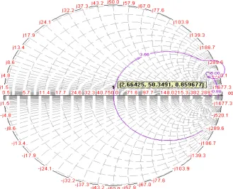
The proposed antenna has been simulated using IE3D software [9]. The physical parameters of all antennas are the same, but the resonant frequency decreased as the iteration order increased, thus the electrical length of the ground plane also decreased in their resonant frequency for the proposed patch antenna. The input characteristics of the fabricated small-size E-H-slotted patch antennas with different parameters are measured through a Vector Network Analyzer. Fig.2 shows the variation of return loss with frequency. Plot result shows resonant frequency 2.66 GHz and total availale impedance band width is 46% from the proposed antenna and -39.42 dB return loss is available at resonant frequency. Which is significant Fig.3 shows the input impedance loci using smith chart. Input impedance curve passing near to the 1 unit impedance circle that shows the perfect matching of input. Fig.4 shows the VSWR of the proposed antenna that is 1.02 at the resonant frequency 2.66 GHz.
ISSN(Online): 2320-9801
ISSN (Print): 2320-9798
I
nternational
J
ournal of
I
nnovative
R
esearch in
C
omputer
and
C
ommunication
E
ngineering
(An ISO 3297: 2007 Certified Organization)
Vol. 4, Issue 8, August 2016
Fig. 2 Return loss vs. Frequency curve for proposed antenna
Fig.3. Input impedance loci using smith chart
ISSN(Online): 2320-9801
ISSN (Print): 2320-9798
I
nternational
J
ournal of
I
nnovative
R
esearch in
C
omputer
and
C
ommunication
E
ngineering
(An ISO 3297: 2007 Certified Organization)
Vol. 4, Issue 8, August 2016
Fig.4. VSWR vs. Frequency curve for proposed antenna
Fig.5 Radiation pattern
V. CONCLUSION
Microstrip patch antennas are increasing in popularity for use in wireless applications due to their low-profile structure. Therefore they are extremely compatible for embedded antennas in handheld wireless devices such as cellular phones, pagers etc. The telemetry and communication antennas on missiles need to be thin and conformal and are often in the form of Microstrip patch antennas. Another area where they have been used successfully is in Satellite communication. An Ultra Wide Band Microstrip E-H-slot antenna is presented. Simulation and measured results of our design show more than -39.42dB return loss at the resonant frequency of 2.66 GHz and VSWR is 1.02 at this frequency.
This novel design can be adjusted to work in higher frequencies which make it possible to add more slots and thus get higher gains with the aim to preserve compactness requirements and to maintain the overall layout as simply as possible and keeping the realization cost very low.
REFERENCES
[1] Bhattacharyya, A. K., and R. Garg, “Generalized Transmission Line Model for Microstrip Patches,” IEE Proc., Vol. 132, Pt. H, 1985, pp. 93-98.
[2] S. Silver, "Microwave Antenna Theory and Design", McGRAW-HILL BOOK COMPANY, INC, New York 1949. [3] C. A. Balanis, "Antenna Theory, Analysis and Design", JOHN WILEY & SONS, INC, New York 1997.
[4] K. F. Lee, Ed., Advances in Microstrip and Printed Antennas, John Wiley, 1997.
[5] Anzar Khan, Rajesh Nema, “Analysis of Five Different Dielectric Substrates on Microstrip Patch Antenna,” International Journal of Computer
Applications ISSN 0975–8887, Volume 55, No.18, October 2012.
[6] R. Garg, P. Bhartia, I. Bahl, A. Ittipiboon, "Microstrip AntennaDesign Handbook", ARTECH HOUSE, Boston 2001. [7] Nenad Hecimovic and Zdenko Marincic,“The improvement of the antenna parameter sinultra-wideband communications” [8] IE3D Software Release 9 and developed by M/S Zeland Software, Inc.
[9] Nazish Irfan, Mustapha C. E. Yagoub, and Khelifa Hettak, “Design of a Microstrip-Line-Fed Inset Patch Antenna for RFID Applications,”
ISSN(Online): 2320-9801
ISSN (Print): 2320-9798
I
nternational
J
ournal of
I
nnovative
R
esearch in
C
omputer
and
C
ommunication
E
ngineering
(An ISO 3297: 2007 Certified Organization)
Vol. 4, Issue 8, August 2016
[10] Indrasen Singh, V.S. Tripathi, “Micro strip Patch Antenna and its Applications: a Survey,” in IJCTA., Sep-Oct, 2011, vol. 2, No. 5, IS S N 2 2 2 9 - 609 3 , pp.1595-1599.
[11] D. M. Pozar, "Input impedance and mutual coupling of rectangular microstrip antennas," IEEE Trans. Antennas andPropagation, vol. AP-30, pp. 1191-1196, Nov. 1982.
[12] James, J.R. and Hall, P.S.: ‘Handbook of Microstrip Antennas’ (Peter Peregrinus).
[13] Douglas H. Werner, Randy L. Haupt and Pingjuan L. Werner, “Fractal antenna engineering: The theory and design of fractal antenna array”,
IEEE antennas and propagation magazine, Vol. 41, No. 5, pp. 37-59, October 1999.
[14] F. E. Gardiol, "Broadband Patch Antennas," Artech House.
[15] D. M. Pozar and D. H. Schaubert, Microstrip Antennas: The Analysis and Design of Microstrip Antennas and Arrays, IEEEPress, 1995. [16] H. F. Pues and A. R. Van de Capelle, "An Impedance Matching Technique for Increasing the Bandwidth of Microstrip Antennas," IEEE Trans.
on Antennas and Propagation., Vol. AP-37, pp. 1345 - 1354, November 1989.
[17] Ashvini Chaturvedi, Yogesh Bhomia and Dinesh Yadav “Truncated Tip Triangular Microstrip Patch Antenna” Electronics & Communication Department National institute of Technology, Surathkal,Karnataka, India ©2010 IEEE.
[18] Dr. Yogesh Bhomia, Yogesh Kr. Sharma, Ramesh Bharti and Amit Kumar Jain “U-Slotted Microstrip Patch Antenna” International Journal of Electronics Communication and Computer Engineering Volume 4, Issue 3, ISSN (Online): 2249–071X, ISSN (Print): 2278–4209. [19] Ravinder Kumar, Arushi Bhardwaj, Dr. Yogesh Bhomia “U-H-Slotted Microstrip Patch Antenna using Two Feeding Techniques” in
“International Conference on "Latest Concepts in Science, Technology and Management (ICLCSTM-16)”ISBN: 978-81932712-4-7.
BIOGRAPHY
Er. Ravinder Kumar received the B.Tech degree from PTU, Punjab in Electronics & communication engineering and
pursuing M.Tech in ECE from PTU, Punjab.
Er. Arushi Bhardwaj received the B.Tech degree from PTU, Punjab in Electronics & communication engineering
and M.Tech in ECE from PTU, Punjab. She is currently working as an Assistant Professor in SSCET, Badhani in Electronics & Communication Engineering.
Dr. Yogesh Bhomia received the B.E. degree from IETE, New Delhi in Electronics & telecommunication and M.E. in