MODELING AND CONTROL OF ACTIVE SUSPENSION FOR A FULL CAR MODEL
ROSHEILA BINTI DARUS
A project report submitted in partial fulfillment of the requirements for the award of the degree of
Master of Engineering (Electrical – Mechatronics and Automatic Control)
Faculty of Electrical of Engineering University Teknologi Malaysia
ABSTRACT
vi
ABSTRAK
TABLE OF CONTENTS
CHAPTER TITLE PAGE
DECLARATION ii
DEDICATION iii
ACKNOWLEDGEMENTS iv
ABSTRACT v
ABSTRAK vi
TABLE OF CONTENTS vii
LIST OF TABLES x
LIST OF FIGURES xi
LIST OF ABBREVIATIONS xiv
LIST OF SYMBOLS xv
LIST OF APPENDICES xvi
1 INTRODUCTION 1
1.1 Introduction 1
1.2 Literature Review of Linear Passive 2 Suspension System
1.3 Literature Review of Linear Semi-active 3 Suspension System
1.4 Literature Review of Linear Active 4 Suspension System
1.5 Literature Review of Vehicle Model 6
1.6 Problem Statement 8
1.7 Objective 9
viii
1.9 Research Methodology 10
1.10 Thesis Outline 13
2 MATHEMATICAL MODELING 14
2.1 Introduction 14
2.2 Mathematical Modeling of Passive 15 Suspension for Quarter Car Model
2.3 Mathematical Modeling of Passive 18 Suspension for Full Car Model
2.4 Mathematical Modeling of Active 24 Suspension for Quarter Car Model
2.5 Mathematical Modeling of Active 26 Suspension for Full Car Model
3 CONTROLLER DESIGN 30
3.1 Introduction 30
3.2 Control Strategy 30
3.2.1 Linear Quadratic Regulator 31
3.2.2 Fuzzy Logic 31
3.2.3 Adaptive Control 32
3.2.3.1 MIT Rule 33
3.2.3.2 Lyapunov Theory 34
3.2.4 H∞Control 34
3.2.5 Sliding Mode Control 35
3.3 Linear Quadratic Regulator (LQR) 36 Controller Design
3.4 Conclusion 37
4 SIMULATION RESULT 38
4.1 Introduction 38
4.2 Simulation Parameter 38
4.5 Comparison between Passive and Active 40 Suspension for Quarter Car Model
4.6 Road Profile 1 for Full Car Simulation 47 4.7 Road Profile 2 for Full Car Simulation 49 4.8 Comparison between Passive and Active 50
Suspension for Full Car Model
4.9 Comparison between Passive and Active 61 Suspension for Full Car Model with
Different Q
4.10 Conclusion 66
5 CONCLUSION AND FUTURE WORK 67
5.1 Conclusion 67
5.2 Recommendation and Future Work 67
REFERENCES 69
CHAPTER 1
INTRODUCTION
1.1 Introduction
Traditionally automotive suspension designs have been compromise between the three conflicting criteria’s namely road handling, load carrying, and passenger comfort. The suspension system must support the vehicle, provide directional control using handling maneuvers and provide effective isolation of passengers and load disturbance. Good ride comfort requires a soft suspension, where as insensitivity to apply loads require stiff suspension. Good handling requires a suspension setting somewhere between it. Due to these conflicting demands, suspension design has to be something that can compromise of these two problems.
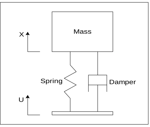
A passive suspension has the ability to store energy via a spring and to dissipate it via a damper. Its parameters are generally fixed, being chosen to achieve a certain level of compromise between road handling, load carrying and ride comfort. An active suspension system has the ability to store, dissipate and to introduce energy to the system. It may vary its parameters depending upon operating conditions.
types of suspension system; passive, semi-active and active suspension system. Traditional suspension consists springs and dampers are referred to as passive suspension, then if the suspension is externally controlled it is known as a semi-active or semi-active suspension.
1.2 Literature Review of Linear Passive Suspension System
3
Mass
Damper Spring
X
U
Figure 1.1: Passive Suspension Component
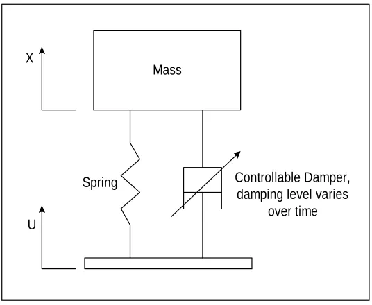
1.3 Literature Review of Linear Semi-active Suspension System
Mass
Controllable Damper, damping level varies
over time Spring
X
U
Figure 1.2: Semi-Active Suspension Component
1.4 Literature Review of Linear Active Suspension System
5
Vehicle System
Controller
Disturbance State
X U
Figure 1.3: Active Suspension Control System
Mass
Damper Spring
X
U
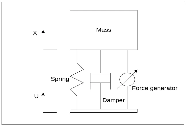
Force generator
Figure 1.4: Active Suspension Component
active suspension, it has that ability to give ride comfort. This is happen by having force actuator control by the controller. The active suspension system is a close loop control system. It will correct the error and gave the output to the desired level. In this project observation will be made at the vertical acceleration of the vehicle body called sprung mass and tire deflection. By using the right control strategy the ride quality and handling performance can be optimize. Therefore, in this project there will be modeling for active and passive suspension only.
1.5 Literature Review of Vehicle Model
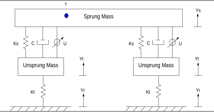
Quarter-car model in Figure 1.5 is very often used for suspension analysis; because it simple and can capture important characteristics of full model. The equation for the model motions are found by adding vertical forces on the sprung and unsprung masses. Most of the quarter-car model suspension will represent the M as the sprung mass, while tire and axles are illustrated by the unsprung mass m. The spring, shock absorber and a variable force-generating element placed between the sprung and unsprung masses constitutes suspension.
7
Sprung Mass
Unsprung Mass
Ks C U
Kt
Ys
Yt
Yr
Figure 1.5: Quarter Car Model
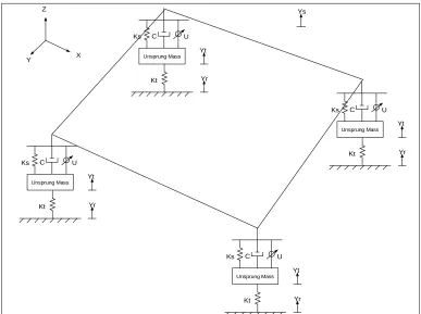
Sprung Mass
Ys
Unsprung Mass
Ks C U
Kt
Yt
Yr
Unsprung Mass
Ks C U
Kt
Yt
Yr
T
Ys
Unsprung Mass Ks C U
Kt
Yt
Yr
Unsprung Mass Ks C U
Kt
Yt
Yr
Unsprung Mass Ks C U
Kt
Yt
Yr
Unsprung Mass Ks C U
Kt Yt Yr Z X Y
Figure 1.7: Full Car Model
1.6 Problem Statement
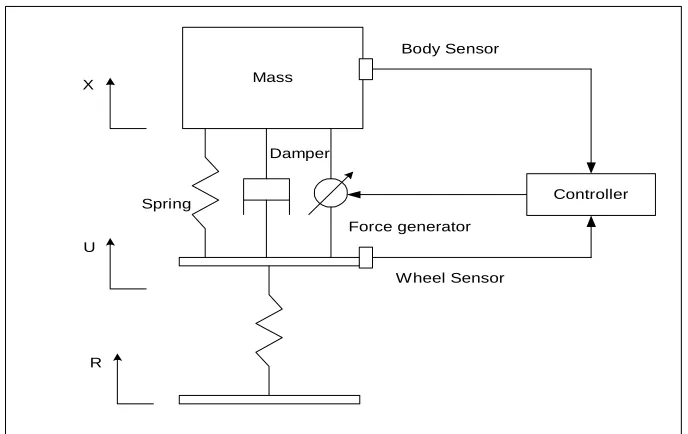
9 Figure 1.8 is needed where there is an active element inside the system to give both conditions so that it can improve the performance of the suspension system. In this project the main objective is to observe the performance of active by using LQR controller and passive suspension only.
Mass
Damper
Spring X
U
Force generator
R
Controller Body Sensor
Wheel Sensor
Figure 1.8: Active Suspension System
1.7 Objective
The objectives of this project are:
i) To establish the active and passive suspension system models.
ii) To establish the mathematical model for active and passive suspension system for quarter and full car models.
1.8 Scope of project
The scopes of work for this project are:
i) To derive and establish the mathematical equation for passive and active suspension for quarter car model for literature purpose.
ii) To implement LQR controller to the active suspension system for full car model.
iii) Computer simulation study by using MATLAB/Simulink
1.9 Research Methodology
a) To understand active and passive suspension component (i) Literature research on active and passive suspension (ii) Identify type of active and passive suspension component. (iii) Literature research about control strategy
b) To derive and establish mathematical model for active and passive suspension system for full car model.
(i) By using physical laws from the suspension components get the state space equation for quarter car model, continue expand the equation to a full car model.
(ii) By using the matrix equation given, get the state space equation. (iii) Continue to get the state space equation for full car model.
c) Implementation of LQR controller into the system. (i) Literature review on the control technique.
11 d) Computer simulation
(i) Involves learning how to transform the state space equation into SIMULINK diagram.
(ii) Simulation of propose controller using MATLAB/Simulink.
e) Result analysis
(i) Involves observation of the preliminary result.
(ii) Simulation to investigate dynamics of active suspension. (iii) Obtain suitable matrix feedback gain.
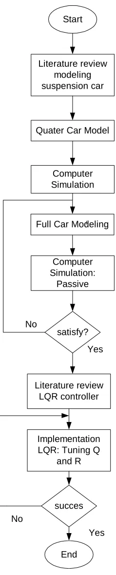
Flow chart in Figure 1.9 shows overall process for the project research.
satisfy? No
Yes Computer Simulation:
Passive Full Car Modeling
Computer Simulation Quater Car Model
Literature review modeling suspension car
Start
Literature review LQR controller
Implementation LQR: Tuning Q
and R
succes
End No
Yes
13
1.10 Thesis Outlines
This project is organized into 5 chapters. Chapter 1 discusses literature review on passive, semi-active and active suspension system. Objectives, scope of project and research methodology are explained in this chapter.
Further explanations on the mathematical modeling for a quarter car and a full car model for active and passive suspension system are included in chapter 2. Mathematical model can described behavior of overall system. This chapter explains method used in this research in order to obtain mathematical model for passive and active suspension system for a full car model.
Chapter 3 reviews relevant literatures and previous works regarding controller design. Controller design for the project is also included which is LQR controller.
In chapter 4, computer simulation between passive and active suspension system will be carried out. There are two types of input disturbance that will be used to test the system. Simulation based on the mathematical model of a full car model is done by using MATLAB/SIMULINK software.
REFERENCES
1. Robert L.W. & Kent L.L., “Modeling and Simulation of Dynamic System”, Second Edition, Prentice-Hall,1997
2. Sam Y.M., Osman H.S.O., Ghani M.R.A., “A Class of Proportional-Integral sliding Mode Control with Application to Active Suspension System” System and Control Letters. 2004. 51:217-223
3. Kim C., Ro P.I, “An Accurate Full Car Ride Model Using Model Reducing Techniques,”Journal of Mechanical Design. 2002. 124:697-705
4. Hespanhna J.P., “Undergraduate Lecture Note on LQG/LGR controller Design”, University of California Santa Barbara; 2007
5. Sam Y.M., Ghani M.R.A and Ahmad, N. LQR Controller for Active Car Suspension.IEEE Control System. 2000. I441-I444
6. Wu S.J., Chiang H.H., Chen J.H., & Lee T.T., “Optimal Fuzzy Control Design for Half-Car Active Suspension Systems” IEEE Proceeding of the International Conference on Networking, Sensing and Control. March. Taipei, Taiwan: IEEE. 2004. 21-23
7. Astrom K.J. & Wittenmark B., “Adaptive Control”, Second Editon, Addison-Wesley Pub, 1995.
8. Chen H.Y. & Huang S.J., “Adaptive Control for Active Suspension System” International Conference on Control and Automatic. June. Budapest, Hungary: 2005.
9. Shariati A., Taghirad H.D. & Fatehi A. “Decentralized Robust H-∞ Controller Design for a Full Car Active Suspension System” Control. University of Bath, United Kingdom. 2004
70 11. Sam Y.M. Proportional Integral Sliding Mode Control of an Active Suspension System. Malaysia University of Technology. PHD Dissertation. Malaysia University of Technology; 2004
12. Ikenaga S., Lewis F.L., Campos J., & Davis L., “Active Suspension Control of Ground Vehicle Based on a Full Car Model” Proceeding of America Control Conference. June. Chicago, Illinois: 2000.
13. Joo D.S. & Al-Holou N., “Development & Evamation of Fuzzy Logic Controller for Vehicle Suspension System,” (1995)MI 48219; pp. 295-299
14. Hung V.V. & Esfandiari S.R., “Dynamic Systems: Modeling and Analysis”, Second Edition, McGraw-Hill, 1997
15. Hyvarinen J.P., “The Improvement of Full Vehicle Semi-Active Suspension through Kenimatical Model,” Master Science Disertation. Oulu of University Findland; 2004
16. Lowen J. Shearer & Kulakowski B.T., “Dynamic Modeling and Control of Engineering Systems” Second Edition, Macmillan Publishing, 1990
17. Gallestey P., “Undergraduate Lecture Note on Applied Nonlinear Control Design”, University of Califonia Santa Barbara; 2000
18. Yoshimura T., Kume A., Kurimoto M., Hino J., “Construction of an Active Suspension System of a Quarter-Car Model Using the Concept of Sliding Mode Control,”Journal of Sound and Vibration.2000.239:187-199
19. Winfred K.N., Dion R.T., Scott C.J., Jon B., Dale G., George W.A., Ron R., Jixiang S., Scott G., Li C. “Development and Control of a Prototype Pneumatic Active Suspension System,” IEEE Transaction on Education. 2002. Vol. 45; No.1; pp. 43-49.