UNCORRECTED PROOFS
1 2 3 4 5 6 7 8 9 10 11 12 13 14 15 16 17 18 19 20 21 22 23 24 25 26 27 28 29 30 31 32 33 34 35 36 37 38 39 40 41 42 43 44 45 46 47 48 49 50 51 52 53 54On-line fault detection method for induction machines based
on signal convolution
Jordi Cusido
1, Luis Romeral
2, Antonio Garcia Espinosa
3*
,y,
Juan Antonio Ortega
1and Jordi-Roger Riba Ruiz
41UPCQ2, Electronic Engineering, Terrassa, Barcelona, Spain
2UPC, Electronic Department, Terrassa, Barcelona, Spain 3UPC, Electrical Engineering, Terrassa, Barcelona, Spain
4UPC, Electrical Engineering, Plac¸a Rei, 15 08700, Igualada, Barcelona 08700, Spain
SUMMARY
A new technique for induction motor fault detection and diagnosis is presented. This technique, which has been experimentally verified in stationary and non-stationary motor conditions, is based on the convolution of wavelet-based functions with motor stator currents. These functions are tuned to specific fault frequencies taking into account motor speed and load torque, thus considering variable operation conditions of the motor. Based on this technique an automatic system for fault diagnosis is also presented, which is suited for easy softwareimplementationQ3. Copyright#2010 John Wiley & Sons, Ltd.
key words: induction machine; fault diagnosis; MCSA; wavelet; diagnosis; on-line fault detection
1. INTRODUCTION
Due to their robustness and reliability, induction motors (IMs) now dominate the field of electromechanical energy conversion, making up the majority of the motors in use in industrial and domestic applications. Among them, squirrel cage IMs are widely used as energy converters to drive any kind of machine, blower, and pump in electric utility, mining, petrochemical, and domestic appliances industries [1]. In many of these applications, the reliability must be of high standards and thus motor operation must be both safe and continuous.
As inverters are used to drive the motor, maintenance of IM has gained considerable interest in recent years in order to reduce output, emergency maintenance costs, broken down equipment, and lost revenues caused by faults, especially since inverters are used to drive the motor. Inverters introduce alterations such as dv/dtor common-mode voltages, which cause premature damage to the machine. An effective method of detecting a motor with an incipient fault could guarantee that the drive is performing the tasks it was designed for. Such a method would allow the creation of Predictive Maintenance Programs and the minimization of undesirables halts in production chains. Moreover, manufacturers and users of these drives are now keen to include diagnosis functions in the control software, as they decrease maintenance costs and to improve salability and reliability.
Among IM faults, bearings, stator faults, eccentricity-related faults and broken rotor bar (BRB), and end ring faults are the most prevalent, and thus demand special attention [3]. Motor Current Signature Analysis (MCSA) is one of the most widely used methods for fault detection analysis in induction machines [4]. MCSA focuses its efforts on the spectral analysis of the stator currents and has been successfully used to detect mechanical faults [5–7] (dynamic eccentricity, BRBs, and bearing damage) and electrical faults [8] (single or multiple-phase short circuits, open phases, and abnormal
*Correspondence to: Antonio Garcia Espinosa, UPC, Electrical Engineering, Terrassa, Barcelona, Spain.
y
E-mail: [email protected]
Q2
UNCORRECTED PROOFS
1 2 3 4 5 6 7 8 9 10 11 12 13 14 15 16 17 18 19 20 21 22 23 24 25 26 27 28 29 30 31 32 33 34 35 36 37 38 39 40 41 42 43 44 45 46 47 48 49 50 51 52 53 54connections). Additionally, MCSA can be extended to others motor variables, such as instantaneous power, to highlight fault characteristics in the spectrum, and to discriminate in case of mixed faults [9]. The advantage of this technique is that it is a well-recognized current standard because of its simplicity and performance: in its simplest form, it only needs one current sensor per machine and is based on a traditional technique such as Fast Fourier Transform (FFT). However, its best performance is achieved at fixed frequency supply and steady state operation. Low slip values resulting from low loads leads to some rotor fault characteristic frequencies close to the stator supply frequency, which makes fault identification difficult due to well-known spectral leakage effects. Moreover, the current spectrum is influenced by many factors, including electric supply, noise, motor geometry, and fault condition. Besides, the FFT analysis is not valid in the case of fault frequency shifts due to variable torque or non-constant speeds [10].
Under these variable conditions, fault harmonics position change with time, and classical FFT cannot be applied, because in transforming into the frequency domain, time information is lost and the event is masked by the transformation.
Even though it is possible to apply a Windowed Fourier Transform (WFT) to follow the signal variation, by computing the FFT every time using only the data within the window and sliding the window along in time, an inconsistent treatment of different current frequencies appears due to the fixed length of the window. Some low frequencies present no full oscillations within the window and their frequency location is lost, while at high frequencies there are as many oscillations and the time location is lost. Therefore, its application for fault detection is limited to motor speeds with very slow changes. Wavelet analysis attempts to solve these problems by decomposing a time series into time/frequency space simultaneously [11]. Wavelets have recently emerged as useful tools for applications such as signal processing, time-frequency analysis, detection of edges and irregularities, feature extractions, and compression of digital data. Wavelet transforms (WTS) decompose the original time-domain signal by computing its correlation with a short-duration wave called the mother wavelet which has a finite length and defined frequency. By correlating this wavelet with the acquired signal the resulting single number gives a measure of the projection of this wave packet on the acquired data during a period equal to the length of the wavelet. Then, by sliding this wavelet along the time series a new time series of the projection amplitude versus time can be constructed. By changing the length of the wavelet and repeating again the former correlation, the original signal is fully decomposed in its frequencyversustime components. With this method, wavelet analysis allows the use of long time intervals where more precise low frequency information is needed and shorter intervals where high frequency information is preferred.
The advantage of using wavelet techniques for fault monitoring and diagnosis of IMs is increasing because these techniques allow us to perform stator current signal analysis during transients. It is then a powerful tool for condition monitoring and fault diagnosis of electrical motors in any operation condition [12].
In recent years WTs have been successfully applied to motor fault detection problems. Continuous WT (CWT) has been used in Ref. [13] to propose a detection method of faulted rotor bars based on ridges of a CWT. Also, CWT is used in Ref. [14] to process both waveforms of electromagnetic torque and phase voltage summation in order to detect windings short circuits in a brushless DC motor.
On the other hand, discrete WT (DWT) is commonly used in electric engineering to detect and diagnose disturbances occurring in three-phase IMs [15–17]. In Ref. [15] the amplitude of relevant coefficients of DWT is used as proper feature coefficients to represent the mechanical faults of the IM. In Ref. [16] an automatic online diagnosis algorithm for broken-bar detection on IMs is performed. The algorithm is based on the DWT analysis of the current transient to compute certain detail level coefficients and a further mean-square function is applied to a subset of those coefficients to obtain a simple weighting function that, according to its value, clearly points the motor condition as either healthy or damaged. The proposal presented in Ref. [17] is based on the analysis of the wavelet packet transform coefficients, and a useful implementation is presented. Discrimination between faults, however, is not possible and faults harmonics under main harmonic is lost, because only two levels are considered in wavelet decomposition. DWT has been also used in Ref. [18] for the diagnosis of rotor bar failures in induction machines by means of analysis of the stator current during transient conditions. In Ref. [19] the DWT is also used without the slip estimation.
UNCORRECTED PROOFS
1 2 3 4 5 6 7 8 9 10 11 12 13 14 15 16 17 18 19 20 21 22 23 24 25 26 27 28 29 30 31 32 33 34 35 36 37 38 39 40 41 42 43 44 45 46 47 48 49 50 51 52 53 54CWT does however have high power computing requirements, and it is not easy to implement in an on line monitoring system. Furthermore DWT dyadic decomposition and hence details containing information of specific motor faults depends on the sampling frequency, which should be changed for variable motor speed and load.
In Ref. [20] a wavelet-transform based technique is used to diagnose BRBs, in which the energy evaluation of a known bandwidth with time-scale analysis is performed. On the other hand in Refs. [21,22] the WT is applied to diagnose the same failure but in this case is performed in the startup stator current.
In Ref. [23] a novel methodology for half-broken-bar detection, which combines current and vibration analysis by correlating the signal spectra to enhance detectability for mechanically loaded and unloaded operating conditions of the motor, which the other isolated techniques are unable to detect.
In this paper, a new method is proposed in order to identify fault frequency components in IMs. The algorithm is based on a convolution of a new specific wavelet-based Agnesi’s function and the acquired stator current signal. In the frequency domain, this function is a selective frequency filter that removes the fundamental frequency component resulting in a more efficient detection of the motor fault characteristic frequencies.
Furthermore, the proposed technique removes not only the supply frequency component, but also others non-fault-related frequency components that may exist in the stator current spectrum due to machine manufacturing or oscillatory operation. This is due to the fact that the employed function is a band pass filter that allows on line tuning in both central frequency and bandwidth of the filter, rejecting any other frequency out of the bandwidth. The evaluation of the fault is achieved by computing the mean power of the filter output signal. A simple slip frequency estimator is proposed in the paper to tune the filters regarding load, thus allowing this technique to be used in non-steady state operation conditions.
The paper is organized as follows. A brief discussion on MCSA is presented in Section 2. In Section 3, wavelet convolution concept is introduced and discussed, including the tuning of the wavelet-based filter using a slip frequency estimator. Faulty model and feature extraction is presented in Section 4 for the IM with broken rotors bars and simulations of the proposed algorithm are presented and discussed. Section 5 shows experimental results. Finally, discussion and conclusion are given in Section 6.
2. MCSA ANALYSIS
The MCSA is considered the most promising non-invasive fault detection method. It permits detection of several common machine faults with simple measurement and process of the stator current and under normal operation of the machine.
Abnormal harmonics, which appear in a stator current, are functions of a number of variables due to the magnetomotiveforce (MMF) distribution and the permeance-wave representation of the air gap. In a variable speed drive, a current control algorithm may provide symmetric stator currents, by applying asymmetrical stator voltages in order to reach this goal despite of the fault producing abnormal harmonics. Therefore, it is important that abnormal harmonic frequencies are independent of these types of drive-systems or control techniques.
The basis of MCSA is that the stator current contains current components directly linked to rotating flux components caused by electrical or mechanical faults. These harmonic current components due to faults can be used for early failure detection.
Three-phase currents under fault conditions can generally be expressed as follows:
iRðtÞ ¼ ffiffiffi 2 p IRcos 2pfstþ ffiffiffi 2 p PN n¼0 IRncosð2pfnt’RnÞ iSðtÞ ¼ ffiffiffi 2 p IScos 2pfst23p þpffiffiffi2P N n¼0 ISncos 2pfnt’Sn23p iTðtÞ ¼ ffiffiffi 2 p ITcos 2pfst43p þpffiffiffi2P N n¼0 ITncos 2pfnt’Tn43p (1)
UNCORRECTED PROOFS
1 2 3 4 5 6 7 8 9 10 11 12 13 14 15 16 17 18 19 20 21 22 23 24 25 26 27 28 29 30 31 32 33 34 35 36 37 38 39 40 41 42 43 44 45 46 47 48 49 50 51 52 53 54whereIR¼IS¼IT¼Iare the RMS values of the fundamental component of the line current.IRn,ISn, andITn, are the RMS values of the fault components andwRn,wSn,wTn, are the angular displacements of the fault components.
The space vector is !
referring to the stator reference frame is obtained by applying the transformation of the symmetrical components:
is ! ¼ ffiffiffi 2 3 r ½iRþiSej2p=3þiTej2p=3 ¼pffiffiffi3 Iej2pfstþI 1ej½2pf1t’1þI2ej½2pf2t’2. . .þInej½2pfnt’n h i (2)
Fault frequenciesf1, . . .,nare related to different faults in the induction machine, such as air gap
eccentricity (3), shorted turns (4), and BRBs (5). Where m is the harmonic order, fs is the main frequency,fiis the mechanical rotor speed in hertz,sis the slip, andpis the number of pairs of poles [6].
fecc¼f1 1m 1s p ; (3) fst¼f1 n pð1sÞ k ; (4) fbrb¼f1 m 1s p s (5)
From these expressions it is apparent that MCSA presents serious drawbacks for locating the fault when either or both the load torque or speed are not constant, because changes insandfsaffect the fault frequency values. In order to overcome this drawback improved MCSA have been proposed [13–27] using a joined time-frequency transformation on the motor stator currents and WT, and featuring extraction and fault diagnosis, even under variable load conditions. However, when using WT it is not easy to define a simple algorithm to develop an automatic fault-detection system due to the predetermined frequency analysis bands associated with discrete filter banks of the transformation. While a DWT with an orthogonal basis function is usually chosen for signal decomposition to avoid redundant of information and allow easy computation, the frequency content of the resulting wavelets details depend on the predetermined acquisition system parameters and motor operation conditions. In this case, wavelet details may not contain the expected fault frequencies.
As viewed from the frequency domain, a WT can be interpreted as a filtering of the signal of interest using a filter bank of the band-pass filter. Utilizing this feature in the frequency domain, filter banks with different central frequencies and energy bandwidths are obtained, which can be tuned to the desired stator current fault frequencies.
3. FAULT DETECTION BY MEANS OF WAVELET-BASED CONVOLUTION
As mentioned above, every wavelet function could be considered as a filter on the frequency domain [10]. By tuning the adequate wavelet function to the operation point (i.e., for the expected frequency) specific fault harmonic detection is thus possible. If online tuning of the wavelet is realized an automatic fault detection method, under variable torque and speed conditions can easily be implemented.
The witch of Agnesi’s is a curve which Cartesian equation is as follows:
y¼ f 3 b t2þf2 b ¼ fb ðt=fbÞ 2 þ1 (6)
UNCORRECTED PROOFS
1 2 3 4 5 6 7 8 9 10 11 12 13 14 15 16 17 18 19 20 21 22 23 24 25 26 27 28 29 30 31 32 33 34 35 36 37 38 39 40 41 42 43 44 45 46 47 48 49 50 51 52 53 54which is equivalent in functional form to the Lorentzian function. Whenfb¼1 this curve becomes very simple and can be expressed as in Equation (7).
y¼ 1
t2þ1 (7)
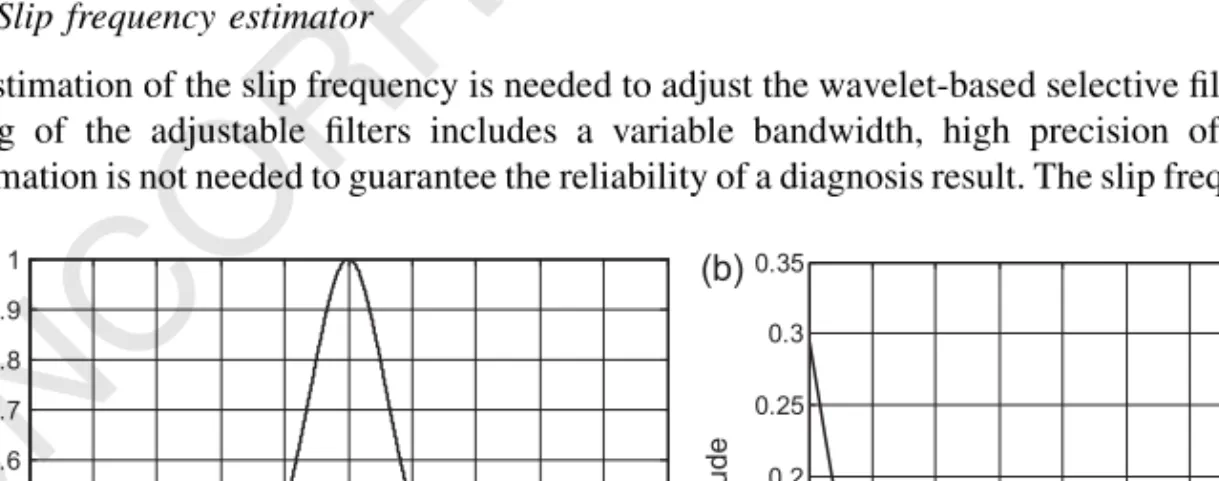
Figure 1a and b shows, respectively, the time domain and the frequency domain representation of the witch of Agnesi’s whenfb¼1 Hz. As shown in Figure 1b, the witch of Agnesi’s behaves as a high-pass filter.
A new wavelet-based family is proposed in this piece of work, obtained by multiplying a sinusoidal function by the witch of Agnesi’s function, defined in the following equation:
’ðtÞ ¼Ccosð2pfctÞ
fb
ðt=fbÞ2þ1
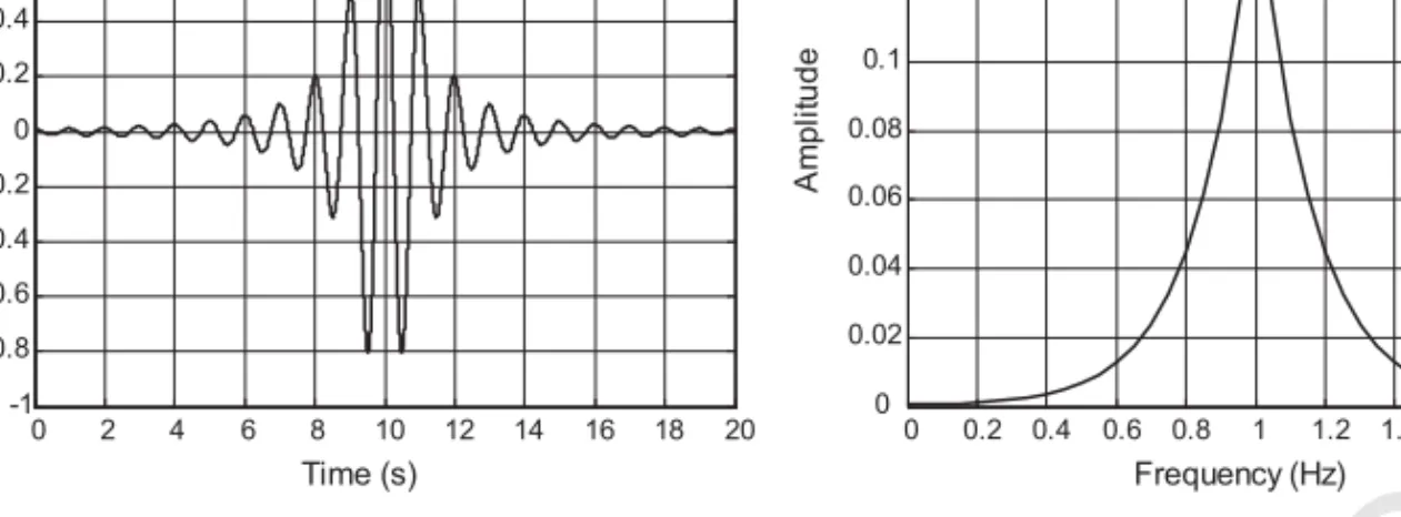
(8) whereCis normalization parameter, andfcandfbdefine the central frequency and the frequency band being analyzed. Figure 2 depicts the responses in time and frequency domains of function expressed in Equation (8) whenfb¼fc¼1 Hz andC¼1, where it is shown that this wavelet-based function behaves as a tunable band-pass filter.
The new function presents a set of characteristics that fit very well within the requirements of harmonic fault detection. These requirements are:
1. the chosen function should be highly selective in frequency domain, presenting a band pass filter characteristic,
2. central frequency and bandwidth must be easily tuned,
3. convolution should not be hard work for the CPU, because the computational burden is lower than that of time frequency transformation.
Wavelet-based function (8) could be considered as a selective filter in whichfcallows for the tuning of the central frequency of the band-pass filter to the expected fault harmonic location andfballows for the adjusting of the bandwidth, taking into account the shifting of this location. In this way, not only fault speed changes, but also torque load variations are considered in fault detection and diagnosis of motor failures. In an expert systemfcwould be defined by the motor speed and nominal slip frequency andfbwould be defined by the slip shifting due to load variations.
3.1. Slip frequency estimator
An estimation of the slip frequency is needed to adjust the wavelet-based selective filter. However, as tuning of the adjustable filters includes a variable bandwidth, high precision of slip frequency information is not needed to guarantee the reliability of a diagnosis result. The slip frequency estimator
-5 -4 -3 -2 -1 0 1 2 3 4 5 0 0.1 0.2 0.3 0.4 0.5 0.6 0.7 0.8 0.9 (a) 1 (b) Time (s) Am pl itud e 0 0.2 0.4 0.6 0.8 1 1.2 1.4 1.6 1.8 2 0 0.05 0.1 0.15 0.2 0.25 0.3 0.35 Frequency (Hz) Am p lit u d e
Figure 1. Time-domain and frequency-domain representations of the witch of Agnesi’s when fb¼1. (a) Time-domain representation of Equation (7). (b) Frequency-domain representation of Equation (7).
UNCORRECTED PROOFS
1 2 3 4 5 6 7 8 9 10 11 12 13 14 15 16 17 18 19 20 21 22 23 24 25 26 27 28 29 30 31 32 33 34 35 36 37 38 39 40 41 42 43 44 45 46 47 48 49 50 51 52 53 54proposed in this paper is based on the idea of using a decoupled torque current component in steady state, also called active stator current. This current can be obtained by projecting the stator current space vector on the stator reference frame fixed to the stator flux-linkage vector.
In the rotating stator flux vector coordinates, two current components can be found by solving the Park’s transformation (9). These currentsisxandisyrotate at the same angular speed that both the stator voltage vector and the stator flux in steady state.
isx isy
¼ cosu cosðu2p=3Þ cosðuþ2p=3Þ
sinu sinðu2p=3Þ sinðuþ2p=3Þ
ia ib ic 0 @ 1 A (9)
whereuis the angle between the stator flux-linkage vector and stator current vector. It is important to note that the drive control knows both the stator flux vector position and flux module by integrating stator voltages: ~vs¼Rs~isþ d dt ~ Fs)F~s¼F~sðtDtÞ þ Zt tDt ð~vsRs~isÞdt¼F _ ejvs (10)
By neglecting the stator resistanceRs, which is an acceptable approximation for motor speeds higher than 20% of the rated, and taking into account nameplate motor characteristics, flux vector is determined. Moreover, the stator current position can be directly read from the control. Thus, the angle
uis perfectly defined and theisycurrent results in the torque-producing stator current component:
Ge¼
3
2pjFsjisy (11)
wherepis the number of pairs of poles. On the other hand, it is well known that the slip angular speed value can be given in a steady state by:
vsl¼ Lsisy TrðjFsj sLsisxÞ ; s¼ 1 L 2 m LsLr (12) where Tr is the rotor time constant, and Lm, Ls, Lr are the magnetizing, the stator and the rotor inductance, respectively. Although the above expression is nonlinear it may be approximated to a constant with an almost insignificant error, particularly for medium and large size motors:
vsl Lsisy Tr F~s k 1 F_isy (13) 0 2 4 6 8 10 12 14 16 18 20 -1 -0.8 -0.6 -0.4 -0.2 0 0.2 0.4 0.6 0.8 (a) 1 (b) Time (s) Am p lit u d e 0 0.2 0.4 0.6 0.8 1 1.2 1.4 1.6 1.8 2 0 0.02 0.04 0.06 0.08 0.1 0.12 0.14 0.16 Frequency (Hz) A m pl itu d e
Figure 2. Time and frequency responses of the Agnesi’s-based mother function. (a) Agnesi’s-based wavelet. (b) Agnesi’s-based wavelet band-pass filter.
UNCORRECTED PROOFS
1 2 3 4 5 6 7 8 9 10 11 12 13 14 15 16 17 18 19 20 21 22 23 24 25 26 27 28 29 30 31 32 33 34 35 36 37 38 39 40 41 42 43 44 45 46 47 48 49 50 51 52 53 54Despite parameterknot being known as a priori, it can be derived from the nominal operation point and considered as a constant with few assumptions, that is, there are not significant changes in machine saturations nor in rotor temperatures, and rotor resistance Rr can be ignored in regard to torque producing equivalent rotor resistance.
By considering (11) and (13) at the nominal operation point, assumingisy nom¼\midis\mid cos phi, and with little algebra, the slip frequency, and hence the slip value, is obtained for a wide range of load variations (14), and tuningfbfrequency in (8) is determined.
vsl
2 3p
Genomvslnom ðjisnomjcos phimotorÞ
2
1
F_isy (14)
Although previous derivations are not particularly rigorous, it should be kept in mind that slip estimation is not for control, but to help better adjust tuning frequencies for fault detection. In the case of a limit, it is enough to consider nominal conditions for fixing fault frequencies fc and actual minimum and maximum motor slip variations for fixing frequency band pass fb. However, when selective filters are thus defined, fault detection is less accurate.
3.2. Power spectral density
In order to diagnose any fault following a disturbance, it is necessary to build a feature extraction technique. A successful feature extraction technique involves the identification of abnormal conditions by the analysis of fault current signatures resulting from different transient disturbances.
The goal of feature extraction is to extract features which are related to specific fault modes. Additionally, reduction of the large amount of spectral information to a usable level is recommended for feature extraction. For these reasons, a Fault Factor (FF) definition is mandatory for the implementation of an on-line diagnostic system.
First, a temporal window starting at the beginning of the acquisition time with a specific width is defined. Then, the resulting feature components can be calculated in several ways, for example, by selecting the maximum component within the window, or by calculating the power of the contained signal.
In a classical Fourier analysis, the power of a signal can be obtained by integrating the power spectral density (PSD), which is the square of the absolute value of the Fourier Transform [22]. The power carried by a defined spectral band can be obtained by integrating the PSD along this spectral band. A similar derivation can be obtained for the DWT, which decomposes a signal in a series of details (frequency components of the signal contained within a predefined band) plus a final approximation. Power detail density (PDD) can be described as the squares of the values of one specific detail. The power energy contained in this detail can be obtained by integration of the resulting PDD. Wavelet convolution, however, does not need to decompose the signal, but only to operate it in time domain. For this reason, a new FF is defined, called mean power of the convolution output (MPCO).
MPCO is calculated by averaging the square of the entire signal inside the temporal window, as expressed in (15): P¼1 T ZT 0 ðiRðtÞ’ðtÞÞ 2 dt (15)
Wavelet convolution shows variations in harmonic amplitude and location, and it is a suitable signal transform to be applied to stationary or non-stationary stator current signals. The MPCO results in an immediate FF for motor fault estimation under either constant or variable load.
3.3. Feature extraction
For full fault condition detection and diagnosis, more than one fault frequency has to be considered at a time. In this case, a set of selective filters tuned at different fault frequencies are needed. They can be easily implemented and tuned by means of the Agnesi’s mother wavelet-based function (8).
UNCORRECTED PROOFS
1 2 3 4 5 6 7 8 9 10 11 12 13 14 15 16 17 18 19 20 21 22 23 24 25 26 27 28 29 30 31 32 33 34 35 36 37 38 39 40 41 42 43 44 45 46 47 48 49 50 51 52 53 54Equation (16) shows the filter bank for full fault detection obtained by adding functions tuned on specific fault frequencies:
’ðtÞ ¼ 2
1þ ðt=fbÞ
2½cosð2pf1tÞ þcosð2pf2tÞ þcosð2pf3tÞ þ. . .þcosð2pfntÞ (16)
It is apparent that more than one fault frequency can be considered for each fault, by taking into account successive fault harmonics in (3), (4), and (5). By doing so, a higher level of accuracy in fault detection is achieved, although computational requirements for the system also increase.
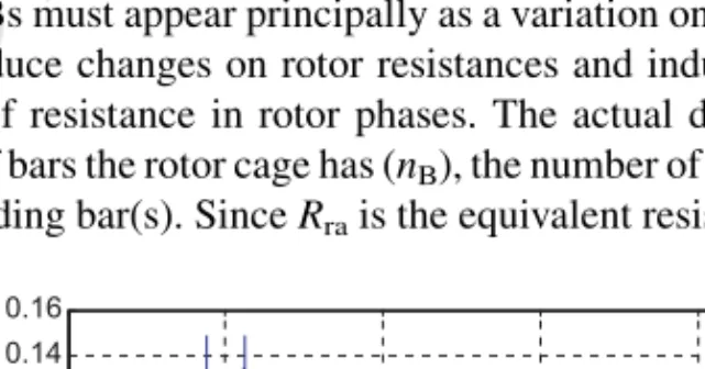
Figure 3 illustrates the filter bank frequency response obtained from function in (16) by considering only the case of broken or damaged rotor bars, and sidebands near the first and fifth harmonics. Broken or cracked rotor bars create a phase shift in the air gap flux resulting in multiple frequency sidebands below the end of the 5th harmonic. For this reason, the fifth harmonic is usually considered for detecting this kind of fault.
Once the mother wavelet-based function to be used is defined and tuned, feature extraction for the fault detection will be performed by convolution of this function and the acquired stator current signal. Convolution must be performed by considering a summation of functions as indicated in Equation (16).
4. FAULT SIMULATION AND DETECTION
A parametric model for faulty IM is developed and used for simulations of damaged motors. The voltage relationship between rotor and stator, torque, speed, and rotor position is well defined in literature [23], and is used here as a basis of faulty motor model.
General IM equations are as follows:
½Vs ½Vr ¼ ½Rs½0 ½0½Rs Is Ir þd dt ½LssðuÞ½LsrðuÞ ½LrsðuÞ½LrrðuÞ Is Ir Gelec¼ 3 2pMRS ~iS~iR ðGelecGmecÞ ¼Dvmþ1 J dvm dt vm¼ dum dt (17)
where V, I, R, and L are voltages, currents, resistances, and inductances, respectively, s and r are subscripts for stator and rotor magnitudes.pis the number of poles pairs,Gelecis the electromagnetic torque,Gmecis load torque,Dis the friction coefficient,Jis the inertia, andumandvmare the rotor position and rotor speed, respectively.
The incidence of BRBs must appear principally as a variation on rotor electrical parameters. Actual incidences of BRB produce changes on rotor resistances and inductances. In this way, BRB can be modeled as variations of resistance in rotor phases. The actual degree of fault and affected phases depend on the number of bars the rotor cage has (nB), the number of contiguous broken bars (nBRB), and the damage in the degrading bar(s). SinceRrais the equivalent resistance of parallelnB/3 rotor bars, if
0 50 100 150 200 250 0 0.02 0.04 0.06 0.08 0.1 0.12 0.14 0.16 f (Hz)
UNCORRECTED PROOFS
1 2 3 4 5 6 7 8 9 10 11 12 13 14 15 16 17 18 19 20 21 22 23 24 25 26 27 28 29 30 31 32 33 34 35 36 37 38 39 40 41 42 43 44 45 46 47 48 49 50 51 52 53 54all but one rotor bar are healthy then the faulty and healthy resistance relationship, also called here resistance fault parametera, can be obtained by the following Equation (18):
a¼R 0 ra Rra ¼ nB nB3nBRB (18) Rather than a resistance variation, an inductance variation occurs due to flux misalignment. The variation appears as variations in phase inductanceL, due to the BRB fault condition the number of rotor bars available is reduced meaning aL increasing as is expressed as follows.
Fulfilling thekvariation, an equivalent equation as used withafor rotor resistance, depending on the number of rotor bars nB and the numbernBRB of BRBs is obtained:
k¼L 0 ra Lra ¼ nB nB3nBRB (19) The variations onR,L, andMpulse at relative rotor speed, that is,sfsregarding the frequencyfsof the rotating stator flux. In case of rotor resistances and rotor inductances,aandkfactors to be taken into account are as follows:
a1¼jacosð2psfsÞjk1 ¼jkcosð2psfsÞj a2¼ acos 2psfsþ 2p 3 k2¼ kcos 2psfsþ 2p 3 a3¼ acos 2psfs 2p 3 k3¼ kcos 2psfs 2p 3 (20)
These variations will give the equation exchanges on fundamental motor equations, which for the case of BRBs are: ½Rr ¼ Rrað1þa1Þ 0 0 0 Rrbð1þa2Þ 0 0 0 Rrcð1þa3Þ 2 4 3 5 (21) LSA MSAB MSAC MSBA LSB MSBC MSCA MSCB LSB 0 @ 1 A MSRAA MSRAB MSRAC MSRBA MSRBB MSRBC MSRCA MSRCB MSRCC 0 @ 1 A MRSAA MRSAB MRSAC MRSBA MRSBB MRSBC MRSCA MRSCB MRSCC 0 @ 1 A LRAMð1RþBAk1Þ LRBMð1RþABk2Þ MMRRACBC MRCA MRCB LSBð1þk3Þ 0 @ 1 A 2 6 6 6 6 6 6 6 4 3 7 7 7 7 7 7 7 5 (22) 4.1. Simulation results
Simulations have been carried out in order to adjust and check the proposed fault detection algorithm. Non-steady-state machine operation was studied, and standard FFT and wavelet convolution, in the sense of this paper, have been applied for feature extraction. From the point of view of shifting of fault frequencies on the spectra, the case of increasing load torque is quite similar to pulsating torque, and only the first case has been studied.
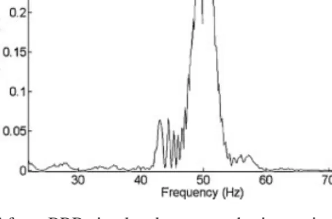
The simulated motor is a 1.1 kW IM, with 28 rotor bars and 36 stator slots. The main parameters of this motor areRs ¼2.03V,Rr ¼2.03V,Ls ¼0.0433 H,M¼0.042 H,Lr ¼0.0433 H, and nominal speed of 1410 rpm. Broken bars have been considered with the motor running from low to high load, that is, from 1450 to 1390 rpm. Fault condition has been introduced by using the Equations (18)–(22). To get the estimation of resistance fault parameter the composition of the rotor three phases distributed on 28 bars has been considered. These assumptions give a fault parameter a¼1, 12 for one BRB. Figure 4 shows the current’s FFT while load torque increases. The harmonic content is evenly distributed into a frequency band going from 50 to 41 Hz. From the figure depicted, it can be concluded
UNCORRECTED PROOFS
1 2 3 4 5 6 7 8 9 10 11 12 13 14 15 16 17 18 19 20 21 22 23 24 25 26 27 28 29 30 31 32 33 34 35 36 37 38 39 40 41 42 43 44 45 46 47 48 49 50 51 52 53 54that fault condition and origin of the fault cannot be easily determined from visual or mathematic analysis of the acquired stator current.
As an alternative to FFT, convolution procedure as defined in Section 3 is hereafter presented. For the fault detection of BRBs, wavelet-based function (8) must be tuned by choosing the central fault frequencies. These frequencies are obtained from Equation (5). By considering the first and fifth harmonics, the resulting fault frequency harmonics for a variable load (slip frequency varying from 3% to 8%) are:
f1¼fsð12sÞ ffi4742 Hz f2¼fsð1þ2sÞ ffi5358 Hz f3¼fsð54sÞ ffi244234 Hz f4¼fsð56sÞ ffi241226 Hz
(23) Figure 4. FFT for a BRB simulated motor under increasing torque conditions.
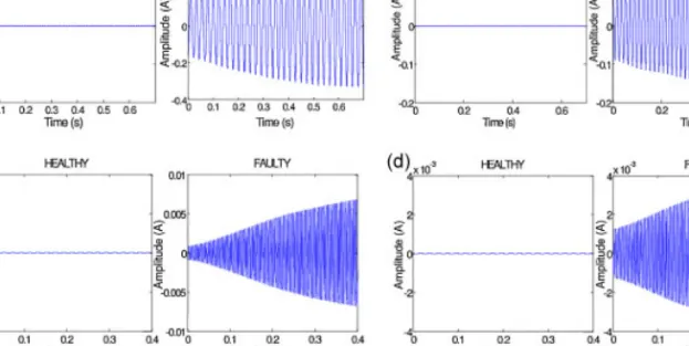
Figure 5. Convolution of simulated current and Agnesi-based wavelet for the four BRB fault frequencies. (a) Fault frequencyf1¼fs(12s). (b) Fault frequencyf2¼fs(1þ2s). (c) Fault frequencyf3¼fs(54s). (d)
UNCORRECTED PROOFS
1 2 3 4 5 6 7 8 9 10 11 12 13 14 15 16 17 18 19 20 21 22 23 24 25 26 27 28 29 30 31 32 33 34 35 36 37 38 39 40 41 42 43 44 45 46 47 48 49 50 51 52 53 54Figure 5 shows the evolution of f1,f2, f3, and f4, where the magnitude variation of these fault harmonics can clearly be appreciated.
The figures show a progressive increment in amplitude, corresponding with an increasing load. A comparison between the MPCO as defined in (15) for healthy and faulty motors is shown in Table I. An increment of the FF is clearly shown for a damaged motor, especially on the most significant frequencies. These results suggest that this technique could assure proper results also in experimental tests.
5. EXPERIMENTAL RESULTS
A three-phase, 1.1 kW, 400/230 V, 50 Hz, 1410 rpm, four-pole IM was used in experiments. A healthy motor was analyzed and three motors were damaged, with a sixth a twelfth and a 28th of its rotor bars artificially broken. The motors were loaded with nominal load torque and subsequently with half of it. The current was measured with a current probe with DC accuracy of3%50 mA at 100 mV/A and frequency range from DC to 100 kHz.
Sampled data was actually treated on-line. The proposed calculation system is able to run on-line in a very short time interval. For example, when dealing with vectors containing 105 components, the complete fault identification system, which includes convolution and energy calculation takes around 15 ms to output the results when using an Intel Pentium Dual Core 2.5 GHz with 4 GB RAM PC running under Windows Vista.
Table I. Power spectral density, increasing load torque.
Healthy Faulty 4 BRB
f1 2.8E01 148.2
f2 1.9E01 105.10
f3 5.1E05 5.4E02
f4 2.6E05 5.5E02
Figure 6. Experimental rig used in experiments.
UNCORRECTED PROOFS
1 2 3 4 5 6 7 8 9 10 11 12 13 14 15 16 17 18 19 20 21 22 23 24 25 26 27 28 29 30 31 32 33 34 35 36 37 38 39 40 41 42 43 44 45 46 47 48 49 50 51 52 53 54Figure 6 shows the experimental rig used for this purpose, where on-line data was acquired through a very-fast PCI-DAS 4020/12 data acquisition card controlled by Matalab/Simulink.
Four rotors were used in experiments, a healthy one and three damaged rotor with artificially BRBs. In order to break/damage the rotor bars, they have been drilled as displayed in Figure 7.
Load torque reduction up to 50% of nominal value results in a slip variation of approximately 50% (14), and as consequence (5) in a shifting of the fault frequencies from nominal fault frequencies at a nominal speed. This displacement defines the minimum bandwidth to be considered during the tuning of the wavelet-based function.
Figure 8 illustrates the convolution of stator current of the four broken bars IM under variable loads with a tuned wavelet-based function, for the four characteristic BRBs fault frequencies. Figure 9 shows multi-wavelet convolution, by using (15) and the four fault frequencies. The fault condition is clearly shown despite load torque variation.
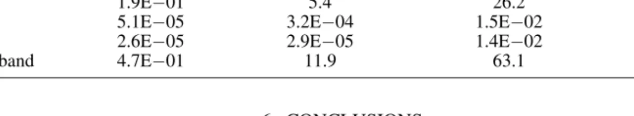
Table II shows how the MPCO is evaluated as a FF for fault detection for the one BRB motor, the two BRB motor and the four BRB motor. In case of fault conditions the magnitude increment is very confident. With about 40 dB of difference between healthy and the less faulty motor, this factor could be used to implement an expert fault detection system.
By using tuning control of the Agnesi’s wavelet-based functions regarding speed reference and estimated torque, automatic fault detection could be implemented in a time domain. This system can be easily implemented in DSP to have an on-line fault detection and diagnosis system, which operates even under variable load torque and variable speed conditions.
Figure 8. Convolution of stator current and Agnesi’s wavelet-based function for the four BRB fault frequencies. (a) Fault frequency f1¼fs(12s). (b) Fault frequency f2¼fs(1þ2s). (c) Fault frequency
f3¼fs(54s). (d) Fault frequencyf4¼fs(56s). 0 0.2 0.4 0.6 0 0.5 Time(s) 0 0.2 0.4 0.6 -0.5 0 0.5 Time(s) Amplitude(A) FAULTY 0 0.2 0.4 0.6 -0.5 0 0.5 Time(s) Amplitude(A) HEALTHY
UNCORRECTED PROOFS
1 2 3 4 5 6 7 8 9 10 11 12 13 14 15 16 17 18 19 20 21 22 23 24 25 26 27 28 29 30 31 32 33 34 35 36 37 38 39 40 41 42 43 44 45 46 47 48 49 50 51 52 53 54 6. CONCLUSIONSThis paper presents an improved MCSA method for IMs fault detection under non-constant torque and speed conditions. The method is based on a convolution of specifically developed wavelet-based functions and motor stator currents, and provides good performance because of fine tuning along time of the wavelets, which adapts itself to variable operation conditions.
The specific wavelet-based function is used like an on-line adjustable filter. The method allows automatically obtaining an index related to the health of the motor based on the MPCO.
Simulation and experimental results confirm expectations, and suggest that this technique would be more suitable for fault detection of IM under non-stationary operation conditions. Furthermore, the proposed method allows easy implementation of automatic diagnosis.
7. LIST OF SYMBOLS
7.1. Symbols
fi mechanical rotor speed (Hz)
fs main frequency (Hz)
f1,. . .,n fault frequencies (Hz)
a fault parameter of the rotor resistance
k fault parameter of the rotor inductance
7.2. Abbreviations
CWT continuous wavelet transform DWT discrete wavelet transform FFT Fast Fourier Transform
MCSA Motor Current Signature Analysis
MMF magnetomotiveforce
MPCO mean power of the convolution output
p number of pairs of poles
s slip
WFT Windowed Fourier Transform
ACKNOWLEDGEMENTS
The authors wish to acknowledge the financial support received from the ‘‘Ministerio de Ciencia y Tecnologı´a de Espan˜a’’ (Spanish Ministry of Science and Technology) for carrying out this piece of work under DPI2007-66688-C02-01 Research Project.
REFERENCES
1. Sadeghian A, Ye Z, Wu B. OnlineQ4 detection of broken rotor bars in induction motors by wavelet packet decomposition and artificial neural networks.IEEE Transactions on Instrumentation and Measurement 2009; 58(7):2253–2263.
Table II. Average energy of the convolution for faulty frequencies.
Healthy Faulty 1 BRB Faulty 2 BRB Faulty 4 BRB
f1 2.8E01 6.5 36.9 148.2
f2 1.9E01 5.4 26.2 105.1
f3 5.1E05 3.2E04 1.5E02 5.4E02
f4 2.6E05 2.9E05 1.4E02 5.5E02
Multiband 4.7E01 11.9 63.1 253.4
UNCORRECTED PROOFS
1 2 3 4 5 6 7 8 9 10 11 12 13 14 15 16 17 18 19 20 21 22 23 24 25 26 27 28 29 30 31 32 33 34 35 36 37 38 39 40 41 42 43 44 45 46 47 48 49 50 51 52 53 542. Bilginer Gulmezoglu M, Ergin S. An approach for bearing fault detection in electrical motors. European Transactions on Electrical Power2007;17:628–641.
3. Nandi S, Toliyat HA, Li X. Condition monitoring and fault diagnosis of electrical motors – a review. IEEE Transactions on Energy Conversion2005;20(4):719–729.
4. Assaf T, Henao H, Capolino GA. A spectral method for on-line computation of the harmonics of symmetrical components in induction machines.European Transactions on Electrical Power2005;15:203–216.
5. Knight AM, Bertani SP. Mechanical fault detection in a medium-sized induction motor using stator current monitoring.IEEE Transactions on Energy Conversion2005;20(2):753–760.
6. Milimonfared J, Kelk HM, Nandi S, Minassians AD, Toliyat HA. A novel approach for broken-rotor-bar detection in cage induction motors.IEEE Transactions on Industry Applications1999;35:1000–1006.
7. Benbouzid MEH, Vieira M, Theys C. Induction motors’ faults detection and localization using stator current advanced signal processing techniques.IEEE Transactions on Power Electronics1999;14:14–22.
8. Thomson WT, Morrrison DK. On-line diagnosis of stator shorted turns in mains and inverter fed low voltage induction motors.Proceedings of IEEE Power Electronics Machines and Drives Conference2002;487:122–127. 9. Tsoumas IP, Georgoulas G, Mitronikas ED, Safacas AN. Asynchronous machine rotor fault diagnosis technique
using complex wavelets.IEEE Transactions on Energy Conversion2008;23:444–459.
10. Huang X, Habetler TG, Harley RG. Detection of rotor eccentricity faults in a closed-loop drive-connected induction motor using an artificial neural network.IEEE Transactions on Power Electronics2007;22:1552–1559. 11. Mallat SG.A Wavelet Tour of Signal Processing, Academic Press: San Diego, 1998.
12. Riera-Guasp M, Antonino-Daviu JA, Roger-Folch J, Pilar Molina Palomares M. The use of the wavelet approxi-mation signal as a tool for the diagnosis of rotor bar failures.IEEE Transactions on Industry Applications2008; 44:716–726.
13. Zhang Z, Ren Z, Hua W. A novel detection method of motor broken rotor bars based on wavelet ridge. IEEE Transactions on Energy Conversion2003;18:417–423.
14. Awadallah MA, Morcos MM, Gopalakrishnan S, Nehl TW. Detection of stator short circuits in VSI-fed brushless DC motors using wavelet transform.IEEE Transactions on Energy Conversion2006;21:1–8.
15. Chen S, Zivanovic R. Modelling and simulation of stator and rotor fault conditions in induction machines for testing fault diagnostic techniques.EuropeanQ5Transactions on Electrical Power2009; Early View.
16. Ordaz-Moreno A, Romero-Troncoso RJ, Vite-Frias JA, Rivera-Gillen JR, Garcia-Perez A. AutomaticQ6online
diagnosis algorithm for broken-bar detection on induction motors based on discrete wavelet transform for FPGA implementation.IEEE Transactions on Industrial Electronics55:2193–2201.
17. Haghjoo F, Mohammad Shahrtash S. Wavelet transform based decomposition and reconstruction for on-line PD detection and measurement. Part I: narrow band components decomposition.EuropeanQ7Transactions on Electrical Power2009; Early View.
18. Ye Z, Wu B, Sadeghian A. Current signature analysis of induction motor mechanical faults by wavelet packet decomposition.IEEE Transactions on Industrial Electronics2003;50:1217–1228.
19. Kia SH, Henao H, Capolino GA.DiagnosisQ8of broken-bar fault in induction machines using discrete wavelet transform without slip estimation.IEEE Transactions on Industry Applications45:1395–1404.
20. Kia SH, Henao H, Capolino G.-A. Diagnosis of broken-bar fault in induction machines using discrete wavelet transform without slip estimation.IEEE Transactions on Industry Applications2009;45:1395–1404.
21. Briz F, Degner MW, Garcı´a P, Bragado D. Broken rotor bar detection in line-fed induction machines using complex wavelet analysis of startup transients.IEEE Transactions on Industry Applications2008;44:760–768.
22. Pineda-Sanchez M, Riera-Guasp M, Antonino-Daviu JA, Roger-Folch J, Perez-Cruz J, Puche-Panadero R. InstantaneousQ9frequency of the left sideband harmonic during the start-up transient: a new method for diagnosis of broken bars.IEEE Transactions on Industrial Electronics56:4557–4570.
23. Rangel-Magdaleno JJ, Romero-Troncoso RJ, Osornio-Rios RA, Cabal-Yepez E, Contreras-Medina LM.NovelQ10
methodology for online half-broken-bar detection on induction motors.IEEE Transactions on Instrumentation and Measurement58:1690–1698.
24. Gritli Y, Stefani A, Rossi C, Filippetti F, Chatti A. Doubly fed induction machine stator fault diagnosis under time-varying conditions based on frequency sliding and wavelet analysis. Proceedings of the IEEE International Symposium on Diagnostics for Electric Machines, Power Electronics and Drives SDEMPED 200: 1–7. 25. Rafiee J, Rafiee MA, Prause N, Tse PW. Application of Daubechies 44 in machine fault diagnostics. IEEE 2nd
International Conference on Computer, Control and Communication IC4-2009: 1–6.
26. Khan MASK, Radwan TS, Rahman MA. Real-time implementation of wavelet packet transform-based diagnosis and protection of three-phase induction motors.IEEE Transactions on Energy Conversion2007;22:647–655. 27. Riera-Guasp M, Antonino-Daviu JA, Pineda-Sanchez M, Puche-Panadero R, Perez-Cruz J. A general approach for
the transient detection of slip-dependent fault components based on the discrete wavelet transform. IEEE Transactions on Industrial Electronics2008;55:4167–4180.
28. Soliman SS, Srinath MD.Continuous and Discrete Signals and Systems, Prentice Hall: Upper Saddle River, 1998. 29. Bose BK.Modern Power Electronics and AC Drives, Prentice Hall: Upper Saddle River, 2002.
Q5 Q6 Q7 Q8 Q9 Q10