Radiographic Imaging of Hip Replacement Hardware
Catherine C. Roberts, MD,* and Felix S. Chew, MD, MBA
†H
ip joint replacement surgery has been the most com-mon type of elective and semi-elective orthopedic op-eration for nearly 25 years. As the science and engineering of implants have evolved, their appearances on imaging and the frequency of common complications have also evolved. Our objectives in writing this article are to explain the postoper-ative appearance of hip joint replacement hardware in terms of materials, design, and function, and to review the imaging appearance of common complications. Our emphasis will be on radiographic imaging because that modality remains the mainstay of follow-up and evaluation.Indications for Hip Replacement
For most joints, the indication for replacement is articular disease involving that joint, most commonly osteoarthritis and rheumatoid arthritis. In these cases, the goal of joint replacement is twofold: first, the restoration of joint function, and second, the elimination of arthritic pain. Joint replace-ment has been proven to be highly efficacious in meeting these goals for most patients with arthritis.1-3 At the hip, additional common indications include femoral head dis-ease, such as osteonecrosis, and femoral neck fractures, such as displaced subcapital fractures, where the risk of posttrau-matic osteonecrosis is high.2-4In the latter circumstance, hip replacement may not really be elective, as the morbidity and mortality from hip fractures in elderly patients who are not treated with hip replacement are both high. Patients with congenital hip disease can benefit from hip replacement.3A hip replacement may also be one component of a larger re-construction following tumor treatment.4Materials Used
in Hip Replacement
The principal material used in joint replacements is metal. The types of metal that are commonly used for implant
com-ponents are pure titanium and titanium alloys (titanium– aluminum–vanadium), and cobalt– chromium alloys. Obvi-ously, all metal components are radiopaque on radiographs, but titanium is less dense than cobalt– chromium, and both are less dense than lead. (The atomic numbers are 22 for titanium, 24 for chromium, 27 for cobalt, and 82 for lead.) The exact appearance on radiographs will depend on the radiographic technique. Titanium alloys are more commonly used in implants of recent vintage, but since the average life of a joint implant easily exceeds 10 years, there are many pa-tients being followed who have cobalt– chromium implants. Stainless steel or titanium may be used for screws and wash-ers.
Bone cement is commonly used to fix components to bone or to fill voids in bone to provide a closer fit with compo-nents. Bone cement is an acrylic plastic (polymethylmethac-rylate) that is polymerized in situ at the time of implant. Because plastic is a hydrocarbon with the same primary atomic constituents as fat (carbon and hydrogen), it is radi-olucent in radiographs. However, bone cement is typically mixed or premixed with barium powder to render it ra-diopaque, and thus it is radiopaque on radiographs, but less dense than metal. Bone cement can be used as both an adhe-sive as well as a space-filler.
Polyethylene is commonly used as a bearing surface, so that most total joint replacements have a convex metal com-ponent articulating with a concave polyethylene liner. The type of polyethylene used in joint replacements is not the common, pliable material used in kitchenware or other light consumer products, but it is an ultrahigh molecular weight material (molecular weight of 3 to 6 million Daltons) that is also used for bullet-proof vests and as the lining for skating rinks and ship docks. A high degree of crosslinking provides increased strength and resistance to surface abrasion.
Ceramics have become more common as prosthetic femo-ral heads and prosthetic acetabular bearing surfaces. The two materials in use are Zirconia,5a strong material with an elastic modulus similar to metals that is more widely known for faux jewelry, and alumina, a hard and rigid material that is more widely known as an ingredient for antacids.
Fixation of Hip Replacements
Fixation of components to bone may occur through direct mechanical fixation, passive interference fit, bone cement,*Assistant Professor of Radiology, Radiology Department Education Coor-dinator, Mayo Clinic College of Medicine, Scottsdale, AZ.
†Professor of Radiology, University of Washington, Seattle, WA.
Address reprint requests to Catherine C. Roberts, MD, Radiology Department Education Coordinator, Mayo Clinic College of Medicine, 13400 E. Shea Boulevard, Scottsdale, AZ 85259. E-mail: [email protected]
320 0037-198X/05/$-see front matter © 2005 Elsevier Inc. All rights reserved. doi:10.1053/j.ro.2005.01.019
and porous ingrowth.6Methods of direct mechanical fixation such as screws are generally obvious on radiographs. Passive interference fit or press fit components are held in position by the shape of the components and the space into which they are tightly fitted. Bone cement may be used as an adhesive, literally gluing the component to bone, or it may be used to fill spaces and contribute to a closer interference fit. Porous ingrowth fixation is based on the principle that remodeling bone can attach itself directly to the component, holding it in place. The key to porous ingrowth is providing a surface that bone can grow into. Special surface treatments that have been used include layers of small metallic spheres, fine wire mesh, and hydroxyapatite crystals. On radiographs, it is difficult if not impossible in most cases to identify the specific type of surface treatment.
Types of Hip Replacements
There are two general types of hip replacement: hemiarthro-plasty and total hip arthrohemiarthro-plasty. The clinical indications for each type are different, and these general types can be iden-tified from radiographs.
Hemiarthroplasty is an operation that replaces one surface of a joint. In the case of the hip, it is always the femoral side that is replaced, so that the resulting articulation is between a prosthetic femoral head and the native acetabular cartilage.
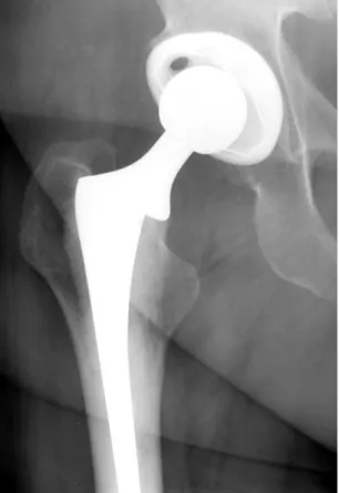
Figure 1 Austin–Moore unipolar hemiarthroplasty. Femoral head and neck are replaced with single-piece prosthesis that articulates with native acetabulum. This prosthesis is loose, as seen by lateral tilt of prosthesis tip (black arrow) and focal lucency at prosthesis– bone interface along proximal, lateral aspect of remaining native femur (white arrowheads).
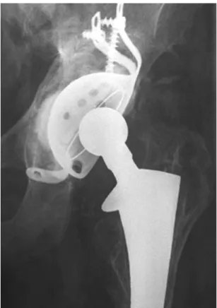
Figure 2 Bipolar hemiarthroplasty. Two-piece prosthesis replacing femoral head and neck articulates with native acetabulum. Unlike unipolar arthroplasty, bipolar prosthesis has an additional region of motion between prosthetic neck and prosthetic head. Similar to the first case, this prosthesis is loose, with lateral tilt of the prosthesis tip (black arrow) and lucency at cement– bone interface along the prox-imal, lateral aspect of the remaining native femur (white arrow-heads).
Figure 3 Femoral head resurfacing arthroplasty. Damaged portions of femoral head have been removed and femoral head remodeled to accept a thin metal cup as a new articulating surface.
Hemiarthroplasty at the hip is generally performed for fem-oral head disease, not hip joint disease. Common clinical indications for hip hemiarthroplasty include osteonecrosis of the femoral head (before secondary osteoarthritis has devel-oped), displaced subcapital fracture of the femoral neck, and resection for tumor. Hemiarthroplasty can be recognized from radiographs because the native acetabular cartilage will be present. One surgical strategy for hemiarthroplasty is re-placement of the femoral head and neck by a one-piece (unipolar) prosthesis that is inserted into the medullary canal of the proximal femur (Fig. 1). In this operation, the femoral head and neck are resected and the prosthesis is secured to the proximal femur by cement or press fit. A more advanced type of hemiarthroplasty is called the bipolar hip replace-ment, in which a two-piece prosthesis is inserted into the medullary canal of the proximal femur (Fig. 2) following removal of the femoral head and neck. The bipolar prosthesis has a femoral stem and a separate head, so that two
articula-tions result: an articulation between the prosthetic head and the native acetabulum, and an articulation between the two components of the prosthesis. Both the unipolar and the bipolar arthroplasty are commonly used today. Recent stud-ies recommend the use of unipolar prostheses instead of bi-polar prostheses in elderly patients with femoral neck frac-tures.7,8A third type of hemiarthroplasty is one in which the articular surface of the femoral head is replaced by a metal cup (Fig. 3). This is referred to as a cup arthroplasty or a femoral head resurfacing arthroplasty. Arthroplasties such as these have been in use since the 1920s.
A total hip arthroplasty (THA) is an operation that replaces both surfaces of the hip joint. The clinical indication for total hip arthroplasty is typically hip joint disease such as osteoar-thritis or rheumatoid arosteoar-thritis. Patients with osteonecrosis are more commonly treated with hemiarthroplasty but total hip arthroplasty is also an effective treatment.9Specifically, pa-tients with Ficat grade III osteonecrosis have a better clinical outcome when treated with a total hip arthroplasty rather
Figure 4 Total hip arthroplasty with cemented femoral and acetab-ular components.
Figure 5 Total hip arthroplasty with noncemented femoral and ace-tabular components.
Figure 6 Hybrid total hip arthroplasty. Femoral component is ce-mented, while acetabular component is cementless.
Figure 7 Ceramic femoral head portion of THA. Ceramic head is more radiolucent than remainder of metallic femoral and acetabular components.
Figure 8 Metal-on-metal total hip arthroplasty. There is no polyeth-ylene liner to separate femoral and acetabular components.
Figure 9 Surface replacement arthroplasty. Damaged portions of ac-etabulum and femoral head have been removed and lined with metal cups.
than a bipolar arthroplasty.10 Because both surfaces of the joint are replaced, the resulting articulation is always be-tween the femoral and acetabular components of the pros-thesis. Total hip replacements can be recognized from radio-graphs by the presence of both femoral and acetabular components. The most common type of total hip replace-ment is one in which the femoral head and neck are replaced
Figure 10 Acetabular reconstruction cage. Acetabulum has been re-vised with cage device to correct protrusio deformity, thus restoring anatomic positioning for femoral component of hip replacement.
Figure 11 Modular hip prosthesis. Custom length prosthesis re-places proximal femur, which was resected for osteosarcoma.
Figure 12 Periprosthetic fracture. Subtle longitudinal fracture line is seen extending distally beyond tip of femoral component (arrow-heads). This fracture was noted at time of surgery and was stabilized with Cerclage wires.
Table 1 Potential Complications of Total Hip Arthroplasty Early
Nerve palsy: sciatic, femoral, peroneal Hemarthrosis
Thromboembolism: deep venous thrombosis, pulmonary embolism
Vascular injuries
Hemorrhage and hematoma formation Bladder infection
Limb length discrepancy Fracture
Late
Loosening Stem failure
Osteolysis (small particle disease) Heterotopic ossification
Stress fractures: femur, pubis Fracture of hardware
Implant sarcoma Either
Infection of joint Dislocation
by a prosthesis that fits inside the medullary canal of the proximal femur, and the acetabulum is replaced by a metal cup with a polyethylene liner. The articulation is thus metal on polyethylene. The components may be fixed to bone using cemented or cementless methods (Figs. 4and5). The com-bination of a cemented femoral component with a nonce-mented acetabular component is called a hybrid THA (Fig. 6). Some total hip replacements use ceramic-bearing surfaces (Fig. 7), and recently, the use of metal-on-metal hip prosthe-sis has become more widespread in the United States (Fig. 8). Total hip replacement by resurfacing both the acetabular and the femoral sides of the joint may also be done. When both the femoral and the acetabular articular surfaces are reshaped and lined by thin metal cups, the procedure is referred to as a surface replacement arthroplasty11 or a “double cup” ar-throplasty (Fig. 9).
Specialized techniques and hardware may be used in cir-cumstances where the native bone stock is insufficient for standard techniques. These circumstances include revisions of failed arthroplasty, developmental hip dysplasia, tumor resection, and severe protrusio acetabuli in rheumatoid ar-thritis. Autograft or allograft bone may be used to buttress the acetabulum or the proximal femur.12Autograft bone is com-monly derived from the femoral head and neck that have been resected during the course of hip arthroplasty. Allograft bone is typically obtained from a bone bank and is usually obtained from cadavers. Acetabular reconstruction cages are components that are used to reconstruct acetabular beds that are deficient in bone stock (Fig. 10). Patients with severe
protrusio acetabuli13 from conditions such as rheumatoid arthritis or patients with marked bone loss from a failed ac-etabular component are typical candidates for acac-etabular re-construction. Following the acetabular reconstruction, a standard total hip prosthesis may be implanted. When the proximal femoral shaft is resected along with the femoral head and neck, a modular prosthesis can be used for recon-struction. The proximal end of this prosthesis may be a unipolar, bipolar, or total hip arthroplasty, while the distal portion that replaces the missing segment of femoral shaft consists of modules customized for the individual patient. The distal portion has an intramedullary stem that fits into the medullary canal and is cemented into place (Fig. 11).
Complications
Complications related to hip replacements are mostly related to fractures, dislocations, component loosening, component failure, and infection. They may occur early during the hos-pital admission or years after the surgery (Table 1). Fractures of the proximal femoral shaft may occur as a complication of insertion of the stem of the femoral component during sur-gery, particularly if it is a press fit component.14Most of these fractures are non-displaced and are often recognized at the time of surgery. Cerclage cables can be used to secure the fracture fragments (Fig. 12). In some cases a nutrient artery canal near the tip of a femoral stem can be confused with fracture.15Comparison with preoperative imaging can help differentiate between an acute fracture and a vascular groove.
Periprosthetic fracture after surgery is most often secondary to prosthesis loosening, occurring at the tip of the femoral endoprosthesis. Fractures occurring after sports-related inju-ries are rare,16likely due to the more sedentary nature of the population receiving the implants. Periprosthetic fractures often require revision of the hip arthroplasty.17
Dislocations are more common in total hip replacement than in hemiarthroplasty and occur typically between the femoral component and the acetabular component. The proximal femur tends to rotate externally, and the head of the prosthesis dislocates anteriorly (Fig. 13). Recurrent disloca-tions often indicate malposition of components that require revision.18 Dislocation of the hip during transfer from the operating table to the gurney for transport to the recover room may occur as an early complication. Postprocedure radiographs that are typically performed in the recovery room can exclude this possibility and document the imme-diate postsurgical appearance of the hip.
Loosening of components may occur from the cyclic me-chanical loading that occurs during weight bearing or may result from biologic action. As implanted, joint replacement
materials are biologically inert. However, repetitive mechan-ical stress on the surface of bearing surfaces causes the abra-sion of small particles. These particles are released from the artificial joint surfaces into the joint capsule, where they may incite a foreign body granuloma response. The particles that have been particularly implicated in this granulomatous sponse are particles of polyethylene. This granulomatous re-sponse results in the resorption of bone at its interface, and this resorption may be visible on radiographs as osteolysis if it is extensive enough (Fig. 14). Osteolysis may be evident as a region of lucency around a component at its interface with bone; this may be seen at the cement– bone interface in the case of a cemented prosthesis or at the metal– bone interface in the case of a noncemented prosthesis. Locations of osteol-ysis surrounding arthroplasty components can be described using the seven femoral zones described by Gruen and three acetabular zones (Fig. 15).19As the zone of osteolysis extends along the interface between bone and component, the com-ponent loses its mechanical attachment. Once gross motion is possible, the zone of osteolysis may become progressively larger, and often a fine zone of sclerosis may form at the margins of the cavity. This process may occur slowly over several years. In general, a zone of osteolysis greater than 2 mm around a component is abnormal20and suggests loosen-ing from foreign body granulomatous reaction. Any gap
be-Figure 14 Osteolysis and polyethylene wear. Femoral component is eccentrically located in acetabular cup, indicating wear of polyeth-ylene liner. Wide regions of lucency surround acetabular compo-nent and proximal femoral compocompo-nent likely secondary to a granu-lomatous response to polyethylene particles.
Figure 15 Periprosthetic zones used to describe location of osteolysis or complication.
tween metal and cement is abnormal. The presence of oste-olysis does not necessarily correlate with clinical symptoms, and clinical symptoms are the usual indication for revision, not radiographic appearance. Because polyethylene particles have been implicated in osteolysis, research has focused ex-tensively on how to reduce the generation of these particles.21 The results of such research have included improved forms of polyethylene with greater resistance to abrasive wear as well as implants that do not use polyethylene.22,23These include implants with ceramic-on-ceramic bearing surfaces as well as metal-on-metal bearing surfaces (Fig. 8).
Infections may occur in the immediate postoperative pe-riod or at a subsequent time. There are no specific radio-graphic features that indicate early infection, but dislocation may be associated with large effusions. In some cases, intra-articular foci of air, beyond the immediate postoperative state, suggest the presence of infection (Fig. 16). Periosteal reaction can also suggest infection.23Imaging-guided arthro-centesis is the best radiological method for identifying infec-tion. In most cases, this may be performed under fluoros-copy. Following informed consent, the patient is placed on the fluoroscopy table in the supine position. The hip capsule will extend from the native bone of the acetabulum to the native bone of the proximal femur, encompassing all of the
exposed components in between (Fig. 17). The easiest target to hit is the prosthetic femoral neck, right in the middle. Following localization of this target under fluoroscopy and preparation of the skin with cleansers and local anesthetic, an 18- or 20-gauge spinal needle can be advanced through the soft tissues until it touches metal. At that point, fluid within the joint may be aspirated. If no fluid is aspirated, a small amount of contrast may be instilled into the joint to confirm location. Washing the joint with an injection of 10 mL of preservative-free saline followed by aspiration will provide material for microbiological analysis, but cultures of fluid from saline wash when the initial aspiration is dry are rarely positive. Because the majority of injected fluid will accumu-late posteriorly, it is generally possible to re-aspirate only 1 to 2 mL. Flexing the hip while aspirating may improve the yield. The definitive method for identifying infection and the caus-ative agents is considered to be surgical biopsy of the syno-vium, a procedure typically beyond the scope of the radiol-ogist. It is sometimes possible to obtain a small piece of synovium using a 22-gauge Sure-Cut (Bauer Medical, Clear-water, FL) biopsy needle placed through the spinal needle. This small piece of tissue can be sent for culture and sensi-tivity.
Confirmed infections require surgical debridement and prolonged antibiotic therapy. Because it is difficult to achieve the requisite concentrations of antibiotics when they are
Figure 17 Aspiration of THA. Conventional subtraction image with intraarticular contrast (black) shows joint space extending from native acetabular bone to native femoral bone.
Figure 16 Infected THA. Small foci of intraarticular gas (arrowheads) are only radiographic indication ofStreptococcus milleriinfection in this patient.
given systemically, methylmethacrylate beads that have been impregnated with antibiotics can be placed directly into the surgical bed for better results (Fig. 18). In most cases, the prosthesis itself must be removed (or retrieved24as the sur-geons refer to it). With the prosthesis gone, patients are not able to bear weight on the affected extremity. To prevent soft-tissue contractures and preserve the limb for possible reimplantation, spacers fabricated from polymethylmethac-rylate may be placed into the joint bed. The PROSTALAC® (Prosthesis of Antibiotic-Loaded Acrylic Cement) device is a temporary implant embedded with antibiotics tailored to the infecting agent (Fig. 19). This implant acts to help treat the infection and to maintain function of the hip between re-moval of the infected hardware and revision of the hip when the infection has resolved. Infections may require treatment for many months before definitive reconstruction can be per-formed. The ultimate outcome of infected hip replacements may be reconstruction with another prosthesis, surgical ar-throdesis of the joint, or permanent pseudoarthrosis of the joint (Fig. 20).
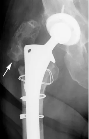
Heterotopic bone may form in the surgical bed follow-ing total hip replacement. Although small amounts of het-erotopic bone formation are unimportant, large amounts of heterotopic may interfere mechanically with motion at the hip and require resection (Fig. 21). Heterotopic bone formation appears to be more common in patients who
have other evidence of excessive bone formation such as hypertrophic osteoarthritis or diffuse idiopathic skeletal hyperostosis.25,26 Therapeutic irradiation of the surgical bed following surgery may prevent recurrence of hetero-topic ossification.27
Figure 18 Antibiotic beads. Polymethylmethacrylate beads are im-pregnated with antibiotics and placed at site of infection, in this case along side plate with dynamic compression screw fixating subtro-chanteric fracture.
Figure 19 PROSTALAC implant. This temporary antibiotic-impreg-nated implant is placed after removal of infected hardware.
Figure 20 Permanent pseudoarthrosis (Girdlestone procedure) of left hip joint following infection. Femoral head has been removed, without replacement.
Fracture of the greater trochanter may occur during sur-gery or as a delayed complication. Because these fractures displace widely, they are virtually impossible to reduce and fix, so they are generally left ununited (Fig. 22). The gluteus medius, one of the strong abductors of the hip, inserts on the greater trochanter. Its loss of action results in a permanent limp.
Approach to
Radiographic Reporting
Radiographs in follow-up of hip replacements have two gen-eral functions, documentation of the procedure and the con-dition of the joint, and surveillance for complications. Joint reconstruction surgeons typically follow their patients sev-eral times in the first year following an implant, and then annually after that. At the time of the first perioperative set of radiographs, it is appropriate to identify the type of prosthe-sis and to search for immediate complications or problems. Because these radiographs are typically obtained using por-table equipment in the recovery room, their quality may be substandard. At our institutions, AP pelvis and true lateral hip radiographs are obtained, allowing assessment of the placement of the components. On the AP radiograph, one can assess the orientation of the acetabular cup in the coronal plane of total hip replacements. The angle between a line drawn across the opening of the acetabular cup and a hori-zontal reference line drawn tangential to the ischial tuberos-ities is called the lateral opening angle and typically measures between 30 and 50° (Fig. 23). On the true lateral projection, the angle between a line drawn against the opening of the acetabular cup and a vertical reference line is called the de-gree of anteversion and typically measures between 10 and 15° (Fig. 24). The position of the center of rotation of the
Figure 21 Heterotopic ossification. Prominent heterotopic bone has formed adjacent to each THA, which likely limits range of motion.
Figure 22 Ununited greater trochanter fracture. Greater trochanter (arrow) has been left unattached to femur.
Figure 23 Normal postoperative total hip replacement shows mea-surement of lateral opening angle on AP pelvis.
Figure 24 Normal postoperative lateral view of total hip replacement showing measurement of degree of acetabular anteversion.
prosthesis should be anatomic, and limb length should be symmetric with the other side. In some patients who have a THA subsequently revised, an extended trochanteric osteot-omy28,29 may be necessary to remove the original femoral component. It is important not to confuse the osteotomy with a fracture (Fig. 25).
At the time of subsequent follow-ups, one should note the results of a comparison with the initial postoperative exami-nation and search for evidence of complications. In the early follow-ups, one should look specifically for fractures; in sub-sequent follow-ups, it is important to search for the compli-cations described above, including asymmetric polyethylene wear (Fig. 14), osteolysis, loosening, heterotopic ossification, subsidence (Fig. 26), textured coating disintegration (Fig. 27), and stress-related changes (Fig. 28). If there has been no change in appearance and there is no evidence of complica-tions, it is sufficient to simply state that there has been no change in appearance and that there is no evidence of com-plications.
Table 2summarizes the radiographic analysis of every total hip arthroplasty.
Conclusion
Hip replacement surgery has been one of the most common elective and semi-elective orthopedic operations for the past 25 years. Radiography remains the mainstay of imaging eval-uation of hip replacements. The various types of hip replace-ments can be recognized on radiographs, and many compli-cations have specific appearances that the radiologist should be familiar with.
Acknowledgements
We extend special thanks to William W. Daniel, MD, and F. Spencer Chivers, MD, for contributing cases.
Figure 25 Laterally located linear lucency of extended trochanteric osteotomy (arrow) should not be confused with fracture.
Figure 26 Right THA with cemented femoral prosthesis and nonce-mented acetabular prosthesis. Femoral prosthesis has subsided into femur approximately 1.5 cm (arrow). Regions of lucency at cement– bone interface (arrowheads) are consistent with loosening from granulomatous small particle disease. Acetabular prosthesis is supe-riorly located and also appears loose.
References
1. Pagnano MW, McLamb LA, Trousdale RT: Primary and revision total hip arthroplasty for patients 90 years of age and older. Mayo Clin Proc 78:285-288, 2003
2. Babis GC, Soucacos PN: Effectiveness of total hip arthroplasty in the management of hip osteonecrosis. Orthop Clin North Am 35:359-364, 2004
3. Hartofilakidis G, Karachalios T: Total hip arthroplasty for congenital hip disease. J Bone Joint Surg Am 86:242-250, 2004
4. Benevenia J, Cyran FP, Biermann JS, et al: Treatment of advanced metastatic lesions of the acetabulum using the saddle prosthesis. Clin Orthop 426:23-31, 2004
5. Santavirta S: Compatibility of the totally replaced hip. Reduction of wear by amorphous diamond coating. Acta Orthop Scand Suppl 74:1-19, 2003
6. Bauer TW, Schils J: The pathology of total joint arthroplasty. I. Mech-anisms of implant fixation. Skeletal Radiol 28:423-432, 1999 7. Raia FJ, Chapman CB, Herrera MF, et al: Unipolar or bipolar
hemiar-throplasty for femoral neck fractures in the elderly? Clin Orthop 414: 259-265, 2003
8. Ong BC, Maurer SG, Aharonoff GB, et al: Unipolar versus bipolar hemiarthroplasty: functional outcome after femoral neck fracture at a minimum of thirty-six months of follow-up. J Orthop Trauma 16:317-322, 2002
9. Babis GC, Soucacos PN: Effectiveness of total hip arthroplasty in the management of hip osteonecrosis. Orthop Clin North Am 35:359-364, 2004
10. Lee SB, Sugano N, Nakata K, et al: Comparison between bipolar hemi-arthroplasty and THA for osteonecrosis of the femoral head. Clin Or-thop 424:161-165, 2004
11. Barnes CL, Collins DN, Nelson CL: Cup arthroplasty, surface replace-ment arthroplasty, and femoral head resurfacing for osteonecrosis. Se-min Arthroplasty 2:222-227, 1991
12. Goldberg VM: Selection of bone grafts for revision total hip arthro-plasty. Clin Orthop 381:68-76, 2000
13. Berry DJ: Antiprotrusio cages for acetabular revision. Clin Orthop 420: 106-112, 2004
14. Masri BA, Meek RM, Duncan CP: Periprosthetic fractures evaluation and treatment. Clin Orthop 420:80-95, 2004
15. Schiessel A, Zweymuller K: The nutrient artery canal of the femur: a radiological study in patients with primary total hip replacement. Skel-etal Radiol 33:142-149, 2004
16. McGrory BJ: Periprosthetic fracture of the femur after total hip arthro-plasty occurring in winter activities: report of two cases. J Surg Orthop Adv 13:119-123, 2004
17. Springer BD, Berry DJ, Lewallen DG: Treatment of periprosthetic fem-oral fractures following total hip arthroplasty with femfem-oral component revision. J Bone Joint Surg Am 85:2156-2162, 2003
Figure 27 Textured coating of implant is disintegrating and free par-ticles can be seen in joint space.
Figure 28 Stress fracture. Laterally located periosteal reaction along femoral shaft, between tip of THA and total knee arthroplasty, in-dicates region of stress fracture.
Table 2 Radiographic Analysis of Total Hip Arthroplasty Is the entire prosthesis imaged?
Check for acetabular version
Check for polyethelene wear. Is femoral head centrally located within acetabular prosthesis?
Check for loosening
Widening of the lucent zone at the cement-to-bone
interface>2 mm
Widening of the lucent zone at metal-to-bone interface
>2 mm
Migration of components from their original positions Development of a lucent gap between metal and
cement Cement fracture Periosteal reactive bone Osteolysis
18. Padgett DE, Warashina H: The unstable total hip replacement. Clin Orthop 420:72-79, 2004
19. Berquist TH, Lewallen DG, McComb BL: The pelvis and hips, in Ber-quist TH (ed): Imaging Atlas of Orthopedic Appliances and Prostheses. New York, NY, Raven Press, 1995, pp 271-352
20. Manaster BJ: From the RSNA refresher courses. Total hip arthroplasty: radiographic evaluation. Radiographics 16:645-660, 1996
21. Digas G, Karrholm J, Thanner J, et al: Highly cross-linked polyethylene in cemented THA: randomized study of 61 hips. Clin Orthop 417:126-138, 2003
22. D’Lima DD, Hermida JC, Chen PC: Polyethylene cross-linking by two different methods reduces acetabular liner wear in a hip joint wear simulator. J Orthop Res 21:761-766, 2003
23. Bauer TW, Schils J: The pathology of total joint arthroplasty. II. Mech-anisms of implant failure. Skeletal Radiol 28:483-497, 1999 24. Hirakawa K, Jacobs JJ, Urban R, et al: Mechanisms of failure of total hip
replacements: lessons learned from retrieval studies. Clin Orthop 420:10-17, 2004
25. Ahrengart L, Lindgren U: Heterotopic bone after hip arthroplasty. De-fining the patient at risk. Clin Orthop 293:153-159, 1993
26. Iorio R, Healy WL: Heterotopic ossification after hip and knee arthro-plasty: risk factors, prevention, and treatment. J Am Acad Orthop Surg 10:409-416, 2002
27. Maloney WJ, Jasty M, Willett C, et al: Prophylaxis for heterotopic bone formation after total hip arthroplasty using low-dose radiation in high-risk patients. Clin Orthop 280:230-234, 1992
28. Della Valle CJ, Berger RA, Rosenberg AG, et al: Extended trochanteric osteotomy in complex primary total hip arthroplasty. A brief note. J Bone Joint Surg Am 85:2385-2390, 2003
29. Meek RM, Greidanus NV, Garbuz DS, et al: Extended trochanteric osteotomy: planning, surgical technique, and pitfalls. Instr Course Lect 53:119-130, 2004