Procedia CIRP 44 ( 2016 ) 287 – 292
2212-8271 © 2016 The Authors. Published by Elsevier B.V. This is an open access article under the CC BY-NC-ND license (http://creativecommons.org/licenses/by-nc-nd/4.0/).
Peer-review under responsibility of the organizing committee of the 6th CIRP Conference on Assembly Technologies and Systems (CATS) doi: 10.1016/j.procir.2016.02.135
ScienceDirect
6th CIRP Conference on Assembly Technologies and Systems (CATS)
Simplifying robot tools by taking advantage of sensor integration in human
collaboration robots
Roman Gerbers
a*; Markus Mücke
a; Franz Dietrich
a; Klaus Dröder
a aInstitute of Machine Tools and Production Technology, Langer Kamp 19, Braunschweig 38106, Germany* Corresponding author. Tel.: +49-531-391-7179 ; fax: +49-531-391-5842. E-mail address: [email protected]
Abstract
Currently, small scale manufacturing is limited to manual assembly due to high product specific costs for fully-automated production. Human robot collaboration (HRC) aims to overcome this problem with semi-automated production by incorporating sensor integrated robotics in more fields of human activity. One key aspect for industrial use of human-robot collaboration is cost efficient adaptability for different manufacturing scenarios. This paper introduces a method that satisfies these demands by simplifying robot tools. Algorithms leveraging the sensor integration of collaboration robots are used to reduce product specific costs. The feasibility of this method is validated by implementation into a flexible screwdriving tool.
© 2016 The Authors. Published by Elsevier B.V.
Peer-review under responsibility of the organizing committee of the 6th CIRP Conference on Assembly Technologies and Systems (CATS). Keywords: Assembly, Tools, Human-robot collaboration
1.Introduction
Human robot collaboration (HRC) has gained a great amount of research effort in recent years. This is due to a large variety of opportunities that come with enabling hybrid workspaces where robots are not separated by safety barriers and are collaborating with human operators. Such workcells enable the implementation of a flexible and reconfigurable production system, where humans handle the tasks that require complex sensing and motions and robots handle monotonous repeated and unergonomic tasks. In this way a production system is achieved that can easily be adapted for different product variants and batch sizes. The advantages of an adaptable production system contribute especially for industries with small scale productions and a wide product variety. Recently, research focused on the technological basics to enable a reliable collaboration, safe and ergonomic for the human operator. This includes vision [1], capacitive [2] or force [3] based sensors for collision avoidance and interfaces or algorithms for simple robot control such as barehanded teaching, voice commands [4] or gestures control [5]. Despite all these advances and innovations it has not yet come to an
extensive introduction of the HRC concept to production environments [6]. Besides challenges with certification of safety functions and operator acceptance, there are also concerns in economic operability. This is due to investments for hardware, which can be very expensive in case of human collaboration robots and engineering. There are still no standardized application scenarios; workcell designs must be developed individually and cost are increased. An important factor to advance HRC is therefore the development of robotic tools with standardized interfaces that enable a fast and cost efficient adaptability of workcells for different tasks and product variants. Such tools have not yet been the focus of research and will be addressed in this work. Since human collaboration robots usually entail a wide field of integrated sensors, they enable the opportunity to develop standardized tools that take advantage of those sensors. By using those integrated sensors, tools can be designed, which are technically much simpler than conventional tools for automation and tool costs can be reduced. In this paper a framework is proposed that will help to methodically develop such simplified tools for human collaboration robots and thus ensure the profitability of HRC in future applications.
© 2016 The Authors. Published by Elsevier B.V. This is an open access article under the CC BY-NC-ND license (http://creativecommons.org/licenses/by-nc-nd/4.0/).
2.Hardware and recent applications for human-robot collaboration
State of the art robotic systems enable HRC particularly through the use of sensitive force / torque sensors in the drive units of the robot axes. The torque of every axis is constantly measured during movement of the robot and collisions can be detected. A difference between the measured torque and a variable with the acceptable value stored in the control system directly triggers the robots safety brakes [7]. The selection of a suitable robot is generally based on the technical specifications of the application to be implemented. Currently, there are six considerable industrial suppliers of HRC-enabled robot systems, which have a certification for industrial application on the German market: KUKA (LBR iiwa), Fanuc (CR-35-iA) Universal Robots (UR3/5/10), ABB (previously Gomtec - Roberta), MRK-Systeme (KR5 SI) and Bosch (APAS) [8]. The systems differ in workspace (up to 1,3 m), repeatability (down to 0.08mm), payload (up to 35 Kg), integration of grippers or multiturn axes and in the integration of additional sensors. Such sensors include vision sensors, 3D area sensors [9] or tactile sensor skins [3] they can be used for the detection of parts for visual servoing [10] or as additional safety feature. A recent development that has not yet been implemented in industrial robots are safety features based on capacitive sensors. Hoffmann et.al. for example developed a capacitive based safety system, to detect humans and static obstacle in close distance to the robot [11]. Since a collision can be detected reliable at an early stage, the speed of robotic movement can be increased in HRC workspaces. Not all sensors that have been developed for HRC are directly integrated into the robot. Some applications integrate additional vision sensors into the workcell to enhance the scope of application. Such systems can be used to detect humans and object in a larger area of the workspace and dynamically adapt the speed according to the distance of the object. A further possibility of such systems is the implementation of online path planning to avoid collisions in advanced by adapting the robots motion sequence [1, 12]. One example for an industrial system that enables the implementation of such applications is the “SafetyEye“ from Pilz GmbH & Co. KG [13].
Recent industrial applications include MRK-Systeme „KR5SI“ robots that are assisting workers in assembly operations at Audi AG by handing coolant expansion tanks in order to optimize ergonomic issues [14], UR 5 robots that are used at the Volkswagen plant in Salzgitter for cylinder head assembly [8], UR 10 robots that are used at BMW for collaborative door sealing [15], Bosch „APAS“ robots handling actuators and sensors at Volkswagen Sachsen [8] and conventional robots expanded with vision-based safety stems at Audi Neckarsulm for acceptance testing for industrial robots in HRC settings [8]. All these applications have in common that they have been development individually with high development cost. To optimize the development process for HRC, more research for standardized platforms, tools and interfaces is necessary.
3.Development approach for simplified robot tools used
in human-robot collaboration
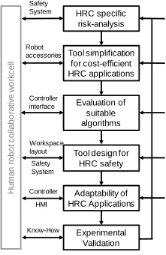
The development of tools for human robot collaboration requires the contemplation of aspects and constraints that go beyond the considerations for conventional robotic tools. Figure 1 shows a framework for methodological development of tools that takes this factors into account.
One of the most important factor is the safety aspect. Since humans have to interact with the robots, the tools have to be designed to prevent injuries and integrated in the overall safety concept. The next aspect is the tool cost reduction. Since HRC is mainly used in frequently changing production scenarios, the adaptability for different task must be more cost-efficient then in conventional automation. This is on the one hand achieved by leveraging the sensor integration in HRC robot and on the other hand by developing control algorithms for HRC which can be reused for similar subtask in different applications. The last aspect is the adaptability for different production scenarios. This is achieved by using standardized interfaces while integrating the tools in the HRC workcell. The development process is always affected by the entire workcell design, such as the safety system, the robotic controller, or the human-machine interface (HMI). However, those systems are not the focus of this paper, but are respected as boundary conditions for the tool development.
Fig. 1. Methodological framework for the development of HRC tools 3.1.Tools specific risk analysis
As a first development step, for HRC tools, it is necessary to verify that the tool can be used in the worst case scenario of a collision. A collision between a collaborative robot and a human leads to injuries of the affected parts of the human’s body, while the components of the robot or the tool is usually not deformed. The potential degree of injury depends on the type of contact (transient/static), the effective robot mass and speed, the duration of impact, the collision surface area and the
HRC specific risk-analysis Tool simplification for cost-efficient HRC applications Evaluation of suitable algorithms Tool design for
HRC safety Experimental Validation Adaptability of HRC Applications H u m a n r obot col la bor a ti v e w o rk cel l Safety System Robot accessories Controller interface Workspace layout HMI Know-How Standardized interfaces Design guidelines and catalogs Libraries Application database Conventional tools Standards and guidelines Controller Safety System
effected body part. The resulting forces may not exceed the maximum permissible body compression for minor injuries. To comply with this requirement medical-biomechanical limits have been specified according to ISO / TS 15066. The standard defines values for the maximum permissible force (shock and clamping / squeezing) and the admissible surface pressure. Additionally, compression constants were identified for each body area, which are used as a characteristic value for the maximum compression displacement until the defined limits are reached. By using mathematical representations of these limits the maximum overall external force can be determined for a collision surface area. This force has to be determined for the worst case with the smallest collision surface and for the most vulnerable body part that might be affected. The maximum transient force has to be compared with the adjustable range of the force sensors in the robot controller. The implementation of the HRC concept is only possible if this force can be detected. All calculations at this stage have to be carried out with respect to the entire HRC workcell design and should be utilized to coordinate requirements for a distance-velocity control.
3.2.Tool simplification for cost-efficient HRC applications For the development of simplified tools for use in HRC two approaches have proven to be suitable. Since a lot of robotic tools have already been developed for fully autonomous production, those tools can be used as basis for simplification. Automatic screwdriving systems for example are equipped with sophisticated vision and force based sensor technology [16]. Costs can be reduced by omitting this hardware leveraging the integrated sensors of the robot. Additional costs can be reduced by the abandonment of a tool specific controller, by integrating the algorithms for operation into the robot controller. Another approach for development of simple tools is the contemplation of tools used for manual operation. For the example of the screwdriving tool, automation could be carried out by adapting an electric powered screwdriver for manual handling as robotic tool. Depending on the desired degree of automation, additional functions may have to be integrated into the robotic tool. Following the example of the screwdriving tool, the screw could be fed by the operator or by additional actuators integrated into the tool. Based on the analysis of conventional tools morphological approaches and utility analysis should be used to determine the optimal solution for an HRC tool for a specific application. Additionally, knowledge databases have to be established for HRC applications to reduce future development effort.
3.3.Evaluation of suitable algorithms
Besides a literature research at conventional platforms for scientific publications, the starting point for the evaluation of suitable algorithms should be established open source libraries. The library OpenCV (Open Source Computer Vision) for example already implements various algorithms for object identification, segmentation and recognition, stereo vision or
machine learning. Additional libraries that can provide suitable algorithms are OpenNN (Open Neural Networks Library), AForge.NET (computer vision and artificial intelligence) and OpenCog (artificial intelligence). The selection of the best suited algorithm should be based on the evaluation of runtime duration, accuracy, repeatability and stability. The algorithms of these libraries are intended for general purpose and further programming work and the combination of multiple algorithms might be necessary to enable a specific application. This increases development time, thus costs are unpredictable. The solution for this problem is the establishment of a library with algorithms leveraging the sensor integration of collaboration robots for specific HRC applications.
3.4.Tool design for HRC safety
Basically, the probability of collision between humans and robots at collaborative workplaces must be minimized by appropriate means. The safety system is responsible for avoiding such collisions. Nevertheless, design requirements for the dynamic and static components of the work system must be respected for the case of a collision. Standards and guidelines define the basic conditions implementation of a tools design. Within this work the German guideline BG/BGIA 2011 and the standard ISO/TS 15066 is applied. In case of a collision no sharp, pointed, cutting edges or rough surfaces have to be in the contact area, no surface load is allowed that exceeds the limits specified for the maximum total force and surface pressure. The workspace has to be designed in such a way that the operator is able to avoid clamping situations. For this purpose, appropriate housing, covers and separation planes have to be used to minimize the risk of injury. The determination of geometric values is still being discussed. So far the guideline BG/BGIA 2011 recommends a distance between two opposite points of the outline of the collision surface of ı5 mm when designing the housing of a tool. Additionally, the ISO / TS 15066 specifies a minimum edges radius of 2.5 mm.
3.5. Adaptability of HRC applications
For integration of the developed tool and algorithms into the entire workcell the focus has to be on the interoperability for further application. This is important at this stage to prevent insular solutions that can only be used within a specific hard-and software environment. The key aspect is the robot controller, because its interfaces define the programming language, the HMI and the integration of sensors and actuators. Currently, most industrial robot controllers have proprietary interfaces that prevent interoperable solutions. Robotic companies have to standardize their interfaces and open their controllers for software package that can be executed in the controller’s real-time core for sensor guided tasks. Since this is currently not the case, open source controllers are an appropriate alternative. One platform that has been proposed for such an implementation, is ROS (Robot Operating System) [17]. With ROS industrial an interface has been established, which can address several industrial robots and provides all the
necessities to develop a standardized ecosystems for HRC that complies with the plug-and-produce [18] concept .
3.6.Experimental Validation
During commissioning of the developed tool, the reliability and safe operating of the system have to be evaluated. Acknowledged issues have to be documented in order to enhance further development processes.
4.Case study: robot assisted disassembly for recycling of
electric vehicle batteries
4.1.Background
The rising number of electric vehicles (EV) will eventually lead to a comparable number of EV batteries reaching their end-of-life. Efforts are therefore being made to develop technologies and processes for recycling, remanufacturing and reusing EV batteries. One important step of many processes is the disassembly of end-of-life EV batteries, which proves a challenging task due to unpredictable lot sizes and volumes, as well as significant variations in battery design between different car models. In response to these challenges and the increasing demand, it is a suitable application for human robot collaboration.
4.2.Scope of assessment
Currently the unscrewing of a bolting takes place manually due to the high number of variants and the unknown product condition during disassembly [19]. The tasks to solve for automation are tool change, releasing of the connector and the transport of the detached screw or nut. Previously developed tool [20, 21] for an automated loosening of fittings, turned out not to be economical. The reasons for this are the mechanical complexity of the tool, the detection of the connectors position (e.g. image processing) and sensor integration into the tool required for the process monitoring. Furthermore, additional handling devices are needed for transportation of the detached components.
By using the proposed method and the integration of the sensors and actuators into the robot it is possible to develop a structurally simple and thus cost-effective tool for the disassembly of threaded connections. With sensor integrated robots for human collaboration, suitable systems are available. In comparison to existing systems the configuration of the tool can be reduced to an electric motor with a tool holder, a standard component removed for a cordless screwdriver. By integrating a gripping mechanism into the tool, the whole process can be realized with one handling device. Due to the intended compact design and the associated low mass, the risks in a collision is reduced and the requirements describing a sufficient housing will not further restrict the robot movements. The unknown product condition at the end of the product life cycle can now be managed with the possibility of additionally manual post-treatment in terms of HRC.
4.3.Tool development
Due to the integration of the sensors and drives into the robot structure, the process control and monitoring can take place into the robot controller resulting in new potentials for process design and process adaptation. This will be shown for the most complex and time-consuming process step the tight fit to compensate lateral tolerances between tool and drive: Criteria for the selection of an optimal algorithm is a minimum throughput time, therefore a small average of seek time for the tolerance compensation. Based on the bolt-hole problem [20– 22] three controlled strategies were identified. Uncontrolled methods were excluded because of their widely varying and unpredictable search behavior. A search algorithm resulting in a rotating linear vibration and a two-axis linear vibration turned out not to be suitable because of the search time depending on the varying position form the screw relative to the beginning of the orbital motion. Also the local denser spaced or frequently intersecting search lines, extended the search time.
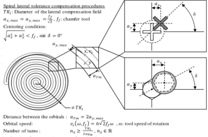
In contrast, the constant spacing between the orbitals of a spiral search strategy ensures that no point is scanned twice. In addition, the beginning of the search path near by the connection position reduces the process time. The developed parametric, spiral search strategy (Figure 2) theoretically offers a proven tight fit by compensating the angular displacement δ based on the coupling of orbital speed and tool speed of rotation. By adjusting the spacing between the orbitals und the orbital speed the process time decrease in accordance with an increasing thread diameter. This also leads to a larger chamfer of fitting (cf. Norm ISO 4014) which describes the local lateral tolerance compensation (Figure 3). Thus compared to the existing tools that are dimensioned for the smallest expected chamfer, the process time can be reduced. The tolerance compensation in the form of a path deviation is enabled by the operation of the robots integrated stiffness regulator. Due to this, the tool behaves as suspended on springs. The process has been optimized by the choice of suitable parameters for the stiffness control.
Fig. 2. Operation principle for a spiral search strategy ݔǡ ݒ௦ ݕ ܽ௬ǡ௫ ܽ௫ ܽ௬ δ ܽ௫ ܽ௬ δ
Distance between the orbitals :்ܽൌ ʹܽ௬ǡ௫
Orbital speed: ݒ௦߱ǡ݂ ൌ ʹ݂߱, ω: tool speed of rotation
Number of turns : ݊ௌ
்
ଶ, ݊ௌא Թ
்ܽ
ႇܶܭ Spiral lateral tolerance compensation procedures
ܶܭ: Diameter of the lateral compensation field
ܽ௫ǡ௫ൌ ܽ௬ǡ௫ൌ
ଶ, ݂: chamfer tool
Centering condition:
Fig. 3. Process time depending on chamfer diameter
Apley et. al demonstrated that force measurement can be used for quality assurance in unscrewing operations [23]. Therefore, a measurement system was implemented to review the tight fit, the loosening and the release of the screw or nut by monitoring the force at the tool and the return stroke of the TCP as shown in Figure 4. In case (a) a transient rising edge in the beginning and fall of the torque at the end of the return stroke indicate a successful process. The significantly lower torque jump in (b) and the following constant torque point to a damaged or cut off drive. In case (c) the continuous maximum torque indicates a non-surmountable loosening torque. A not completely unscrewed thread shows the high torque at the end of the return stroke in case (d). The other necessary process steps are also controlled with the use of tactile functionalities of the robot controller. The contact between the tool and component can be detected with the increase of the measured torque in the joints. The tool change is done using a robot motion for plugging and unplugging of conventional - used in the manual tasks - tool attachments with a clamping by spring force. Thus an additional actuator for receiving the tool attachments is obsolete. The structure of the gripping mechanism was simplified in a morphological design process to a one finger gripper with one actuator. While using a tight fit between the tool and the component as gripping point.
Fig. 4. Measured forces on the tool and the return stroke of the TCP
4.4.Results of the evaluation
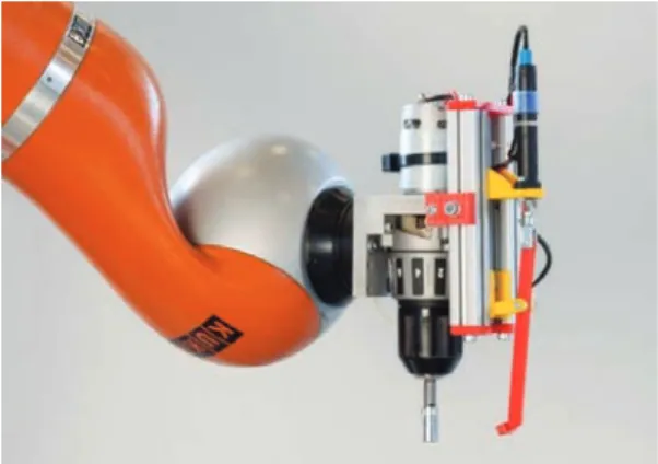
The prototype of the developed screwdriving tool, with an electric motor and a pneumatic actuated gripper is shown in Figure 5. The hardware only requires simple electronic motion control units that are driven from the robot controller. The total hardware cost of the prototype is about 160 € (80 € pneumatic
components, 60 € motion control electronics and drive, 20 €
additional components). Compared to the unscrewing system developed by Apley et. al. [23] costs are significantly reduced by waiving an active, driven and controlled compensation mechanism used for unscrewing operations. The functional integration of a screw gripper makes additional handling equipment for removal of loosened parts unnecessary which also reduces hardware cost. Furthermore, developed algorithms can be reused for other joining operations and the robot sensors are available for other tasks. This also justifies the high purchase price for collaborating robots because cost-efficient adaptability for different applications is enabled. For safe collaboration with human operators a housing for the tool was designed in accordance to the specifications described in section 3.4.
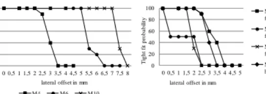
Fig. 5. Prototype of screwdriving tool without housing Figure 6 shows a series of measurements on a test rig to validate the functionality of the system based on the process step tight fit. The measurement was performed ten times for each measuring point with different directions of the positional deviation. The results verify the functionality of the implemented process. However, also a strong dependence of the maximum compensable tolerance depending on the diameter of the screw head or the nut and their geometric shape was observed. The application of the process on different battery systems shows that edges in the workspace interfere the tight fit. To overcome this problem further development of the process has to take the entire disassembly cell into account.
By incorporating this search algorithm in a standard library for the HRC, this functionality can be applied on other joining problems. The monitoring of the moment and the return stroke can easily be transferred to other joining operations such as bolting. With the developed solutions further development of screwing tools become easier.
Fig. 6. Experimental results of tool validation
5.Conclusion and Outlook
The increasing demand for productive and flexible production systems will lead to a growing implementation of robotics in more fields of human activity. An economic implementation of HRC can only be successful, if product specific costs are reduced and the adaptability for different production scenarios is possible with low effort. This work presented a methodological approach that aims to satisfy the demand of a production system that can be flexible adapted for different scenarios reducing tool specific costs. The feasibility of the development approach is demonstrated in a case study for robot assisted disassembly for recycling of electric vehicle batteries. A simplified and cost effective tool for unscrewing of a wide variety of screws and nuts is presented. The evaluation indicates that a reliable use of the tool is feasible.
Further the results show that the proposed method is a good framework for the development of HRC workspaces. However further work is necessary to provide a more extensive basis for a rapid development processes of HRC workspaces. Design catalogs and guidelines for HRC tools have to be elaborated, standardization has to be advanced including a library for algorithms that generally enables HRC applications, a HMI for simple ergonomic use of human collaboration robots and an open controller platform with appropriate interfaces. Since ROS provides all the necessities to develop such a standardized HRC ecosystem, further research will focus on the implementation of the proposed features within this system.
Acknowledgements
The authors like to express their gratitude to the German Federal Ministry for the Environment, Nature Conservation and Nuclear Safety for supporting the project ‘LithoRec II – Recycling of Lithium-ion Batteries’ with the promotional reference 16EM1021.
References
[1] Wang L, Schmidt B, Nee AY. Vision-guided active collision avoidance for human-robot collaborations. Manufacturing Letters 2013;1(1):5–8. [2] Šekoranja B, Bašić D, Švaco M, Šuligoj F, Jerbić B. Human-Robot
Interaction Based on Use of Capacitive Sensors. Procedia Engineering 2014;69:464–8.
[3] Bdiwi M. Integrated Sensors System for Human Safety during Cooperating with Industrial Robots for Handing-over and Assembling Tasks. Procedia CIRP 2014;23:65–70.
[4] Schmidt B, Wang L. Contact-less and Programming-less Human-Robot Collaboration. Procedia CIRP 2013;7:545–50.
[5] Coupeté E, Moutarde F, Manitsaris S. Gesture Recognition Using a Depth Camera for Human Robot Collaboration on Assembly Line. Procedia Manufacturing 2015;3:518–25.
[6] Michalos G, Makris S, Tsarouchi P, Guasch T, Kontovrakis D, Chryssolouris G. Design Considerations for Safe Human-robot Collaborative Workplaces. Procedia CIRP 2015;37:248–53.
[7] Luca A de, Flacco F. Integrated control for pHRI: Collision avoidance, detection, reaction and collaboration. In: 2012 4th IEEE RAS & EMBS International Conference on Biomedical Robotics and Biomechatronics (BioRob 2012), p. 288–295.
[8] Heyn H, Krüger T. Towards Human-Robot Cooperation – Systematic Approach and Applications within the Volkswagen Group. International Conferenceon on Intelligent Robots and Systems, Hamburg; 2015. [9] Fanuc. Robot finder LR Mate Arc welding CR-35iA Paint Robots M-10iA
M-20 M-410 M-710iC M-900 M-2000iA R-1000iA R-2000 M-1iA M-2iA M-3iA Range overview Accessories Collaborative robot CR-35iA. http://www.fanuc.eu/pt/en/robots/robot-filter-page/collaborative-cr35ia. Accessed 24 November 2015.
[10] Cherubini A, Passama R, Fraisse P, Crosnier A. A unified multimodal control framework for human–robot interaction. Robotics and Autonomous Systems 2015;70:106–15.
[11] Hoffmann A, Schierl A, Angerer A, Stüben M, Vistein M, Reif W. Robot Collision Avoidance Using an Environment Model for Capacitive Sensors. In: Planning, Control, and Sensing for Safe Human-Robot Interaction, IEEE Intl. Conf. on Robotics and Automation (ICRA), Seattle, USA; 2015. [12] Flacco F, Kroeger T, Luca A de, Khatib O. A Depth Space Approach for
Evaluating Distance to Objects. J Intell Robot Syst 2014.
[13] Pilz GmbH & Co. KG. Safe camera system SafetyEYE. https://www. pilz.com/en-DE/eshop/00014000337042/SafetyEYE-Safe-camera-system. Accessed 2 December 2015.
[14] Audi AG. New human-robot cooperation in Audi’s production processes. http://www.audi.com/aola/brand/en_lc/tools/news/pool/2015/02/New_hu man-robot_cooperation_in_Audi_s_production.html. Accessed 22 November 2015.
[15] Knight W. How Human-Robot Teamwork Will Upend Manufacturing. http://www.technologyreview.com/news/530696/how-human-robot-teamwork-will-upend-manufacturing/. Accessed 22 November 2015. [16] Tsujimura T, Yabuta T. Adaptive force control of screwdriving with a
positioning-controlled manipulator. Robotics and Autonomous Systems 1991;7(1):57–65.
[17] Tsarouchi P, Makris S, Michalos G, Matthaiakis A, Chatzigeorgiou X, Athanasatos A et al. ROS Based Coordination of Human Robot Cooperative Assembly Tasks-An Industrial Case Study. Procedia CIRP 2015;37:254–9.
[18] Scrimieri D, Antzoulatos N, Castro E, Ratchev SM. Automated Experience-Based Learning for Plug and Produce Assembly Systems. IFAC-PapersOnLine 2015;48(3):2083–8.
[19] Wegener K, Chen WH, Dietrich F, Dröder K, Kara S. Robot Assisted Disassembly for the Recycling of Electric Vehicle Batteries. Procedia CIRP 2015;29:716–21.
[20] Kahmeyer M. Flexible Demontage mit dem Industrieroboter am Beispiel von Fernsprech-Endgeräten. Berlin, Heidelberg, New York, London, Paris, Tokyo, Hong Kong, Barcelona, Budapest: Springer; 1995. [21] Nave M, Jünemann R. Beitrag zur automatisierten Demontage durch
Optimierung des Trennprozesses von Schraubenverbindungen. 1st ed. Dortmund: Praxiswissen GmbH Gesellschaft für innovative Qualifizierung; 2003.
[22] Schweigert U. Toleranzausgleichssysteme für Industrieroboter am Beispiel des feinwerktechnischen Bolzen-Loch-Problems. Berlin, New York: Springer; 1992.
[23] Apley DW, Seliger G, Voit L, Shi J. Diagnostics in Disassembly Unscrewing Operations. International Journal of Flexible Manufacturing Systems 1998;10(2):111–28. 0 20 40 60 80 100 0 0,5 1 1,5 2 2,5 3 3,5 4 4,5 5 5,5 6 6,5 7 7,5 8 T ig h t f it p ro b a b ilit y lateral offset in mm
Influence of lateral offset as a function of the shaft diameter at external hexagon drive
M4 M6 M10 0 20 40 60 80 100 0 0,5 1 1,5 2 2,5 3 3,5 4 4,5 5 T ig h t f it p ro b a b ilit y
Influence of lateral offset depending on the drive type
M4 Torx filister head M4 Phillips filister head M4 Phillips flat head M4 External hexagon lateral offset in mm