Downloaded from: https://research.chalmers.se, 2021-01-23 05:08 UTC
Citation for the original published paper (version of record):
Mirani, A., Agrell, E., Karlsson, M. (2021)
Low-complexity geometric shaping
Journal of Lightwave Technology, 39(2): 363-371
http://dx.doi.org/10.1109/JLT.2020.3033031
N.B. When citing this work, cite the original published paper.
research.chalmers.se offers the possibility of retrieving research publications produced at Chalmers University of Technology. It covers all kind of research output: articles, dissertations, conference papers, reports etc. since 2004.
research.chalmers.se is administrated and maintained by Chalmers Library
Low-Complexity Geometric Shaping
Ali Mirani
, Erik Agrell
,
Fellow, IEEE,
and Magnus Karlsson
,
Senior Member, IEEE, Fellow, OSA
Abstract—Approaching Shannon’s capacity via geometric shaping has usually been regarded as challenging due to mod-ulation and demodmod-ulation complexity, requiring look-up tables to store the constellation points and constellation bit labeling. To overcome these challenges, in this paper, we study lattice-based geometrically shaped modulation formats in multidimen-sional Euclidean space. We describe and evaluate fast and low complexity modulation and demodulation algorithms that make these modulation formats practical, even with extremely high constellation sizes with more than 1028points. The uncoded bit error rate performance of these constellations is compared with the conventional quadrature amplitude modulate (QAM) formats in the additive white Gaussian noise and nonlinear fiber channels. At a spectral efficiency of 2 bits/sym/polarization, compared with 4-QAM format, transmission reach improvement of more than 38% is shown at the hard-decision forward error correction threshold of2.26×10−4.
Index Terms—Optical communication, coherent receiver, mul-tidimensional modulation format, geometric shaping, lattice.
I. INTRODUCTION
M
UCH effort have been put on different aspects of optical links to overcome the need for higher information throughput. Among them, the optimization of modulation formats has been an important research area [1], [2]. One way to increase the transmission rate is to use higher-order modulation formats, i.e., transmitting more information bits in each channel use. However, higher-order modulation formats require more signal power to achieve a certain performance which can be a problem because fiber links are limited in transmitting power by fiber nonlinearities [3, chap. 8]. Another method to improve the transmission rate in optical communication is to use constellation shaping. Shaping can be performed in two different ways, which can also be combined with each other, known as probabilistic shaping [4] and geometric shaping [5]. Probabilistic shaping uses a nonuniform distribution over a regular, low-dimensional constellation such as QAM, whereas geometric shaping refers to a nonrectangular constellation, often multidimensional, with a uniform distribution. Recently, probabilistic shaping has been extensively studied and shown to provide rate adaptability and energy efficiency gains [6], [7]. However, its need for a distribution matcher increases the system complexity. Also geometric shaping has been studied, although less, but used to design nonlinear tolerant and multidimensional constellations [8], [9], [10].A. Mirani and M. Karlsson are with the Department of Microtechnology and Nanoscience, Chalmers University of Technology, SE-41296 Gothenburg, Sweden (email: [email protected]; [email protected]).
E. Agrell is with the Department of Electrical Engineering, Chalmers University of Technology, SE-41296 Gothenburg, Sweden (email: [email protected]).
Exploiting multidimensional modulation formats brings about two independent performance gains known as coding gain andshaping gain. Coding gain comes from the fact that constellation points can be packed more densely in multidimensional space, and the shaping gain is achieved when the constellation boundary is closer to a hypersphere. The maximum shaping gain that can be obtained by a spherical boundary in high dimensional space is 1.53 dB compared to a cubic boundary [11].
The electromagnetic field has 4 degrees of freedom [12] and combined with coherent detection schemes, receivers with improved sensitivity can be utilized to compensate for channel distortions, i.e., polarization drift and nonlinear effects [13]. Furthermore, taking advantage of wavelengths, time slots, and spatial modes/cores in a fiber link can increase the available degrees of freedom and increase data transmission rates. Typ-ically, these dimensions have been modulated independently in fiber optic communications, but there are studies that show that optimizing formats in many dimensions will improve the performance of the system.
Modern research on multidimensional modulation for-mats in optical communication systems dates back to 2009 when the possibility of optimizing the constellations in the 4-dimensional space formed by the optical field was demon-strated [14]. High-dimensional modulation formats were then optimized by sphere packing to find the most power-efficient and spectral-efficient modulation formats [15]. Later on, there were even more research on employing higher dimensions such as 8 and 24. In [16], 8-dimensional lattice modulation for-mats were simulated based on spherical cut [17] with 128 and 256 constellation points. Also, by combining pulse-position modulation with polarization-switched quadrature phase-shift keying (QPSK), an 8-dimensional modulation format was ex-perimentally investigated in [18] showing significant improve-ment over polarization multiplexed QPSK. In [19] and [20], 8- and 24-dimensional modulation formats using temporally adjacent time slots were used to transmit data over short-reach intensity modulated links. In [21], multidimensional modula-tion formats in coherent optical systems were demonstrated by spherical-cut constellations and block-coded modulation. The advantages of combining multidimensional shaping with non-binary coded modulation were shown in [22]. An optimized 8-dimensional modulation format based on polarizations and time slots was compared with polarization multiplexed binary phase-shift keying (BPSK) to show its improved nonlinear performance in [23]. In [24], multidimensional constellations based on lattices, so called Voronoi constellation (VC), were investigated and were suggested as coded modulation schemes with higher shaping gains than generalized cross constellations indicated in [11]. Also, the densest lattices for the sphere packing problem in different dimensions with fast and
low-complexity modulation and demodulation algorithms were studied in [25] and [26]. In [27], to achieve high spectral efficiency (SE), digital backpropagation was combined with trellis shaping where bit-interleaved coded modulation and a convolutional shaping code were used for lower and higher bit levels, respectively. The complexity of this method is mainly due to the Viterbi algorithm decoder in the transmitter [28].
In this paper, we evaluate the performance of coherent fiber links with ultra-large Voronoi constellations with more than 1028 points, which has never been done before to our
knowl-edge. The low-complexity algorithms are numerically com-pared with maximum likelihood (ML) detection and shown to perform almost equivalently at high SE or high signal to noise ratio (SNR). Low-complexity natural binary and quasi-Gray constellation bit labelings are used to map bits to constellation points and their performances are compared. The asymptotic power efficiency of lattices for different dimensions and SEs, as well as the optimum choice of Voronoi boundary are studied. The uncoded bit error rate (BER) performance of these VCs are then examined in the additive white Gaussian noise (AWGN) and nonlinear fiber-optic channels.
The remainder of the paper is organized as follows. In section II, we describe the lattice theory, lattice properties, and how to use them for finite constellations. Fast modulation and demodulation algorithms for lattice-based VCs are then presented in section III. In section IV, figures of merit for comparing modulation formats at different dimensions are defined and numerical simulations are applied to demonstrate these concepts. We finally give the performance of the VCs in section V in both the AWGN and the nonlinear fiber-optic channels. The conclusion of this paper is presented in section VI.
II. PRELIMINARIES
In this section, we introduce the basics of lattice theory, lattice properties, constellations and their construction based on lattices.
In general, lattices are periodic structures of points in
N-dimensional Euclidean space. Mathematically, lattices can be described and constructed using a set of linearly indepen-dent vectors g1,g2,· · ·,gl ∈ RN in N-dimensional space where R is the set of real numbers and l ≤ N. Linear combination of these vectors with integer coefficients creates the lattice points which are then defined by
Λ =nz1g1+· · ·+zlgl zi∈Z, i∈ {1,· · ·, l} o . (1) In this paper, we only consider full-rank lattices, i.e., l=N. In order to describe lattices in a more compact way, the square generator matrix G= [g1, g2,· · ·, gN]∈RN×N is defined, whereg1, . . . ,gN are column vectors. Thus,det(G)6= 0and
Λ =Gz|z∈ZN . It should be noted that the generator matrix is not unique and different generator matrices can create the same lattice points.
In communication systems, information bits are mapped to symbols that are sent every Ts seconds and modulate a
carrier which are then transmitted through a channel. Symbols are selected from a set of M elements, the constellation,
𝑉(𝟎) a 𝒈1 𝒈2 𝑉𝑟 𝐚 + 𝑉𝑟 𝐴2𝑙𝑎𝑡𝑡𝑖𝑐𝑒
Fig. 1: Properties for A2 lattice. The vectors g1 = [1 0]T
andg2= [1/2 √
3/2]T show the basis vectors of the lattice.
Circular points show the lattice points, small hexagons are the Voronoi regions around the lattice points and V(0) is the Voronoi region of the lattice. The filled points are the selected constellation points with a Voronoi cut. The boundary
Vrindicates the scaled Voronoi region withr= 4, containing
r2= 16points and ais the shift vector.
C = {c0,c1, ...,cM−1}. Constellations can be described in
an N-dimensional space and therefore each symbol (ci) is
represented by anN-dimensional vector. In this work, an equal probability of generating each symbol from the constellation is considered. Therefore, the entropy of this source or average information of each symbol is m = log2M bits, and the
information rate of the source is equal to Rb = Tms bits per
second.
The average energy per symbol is defined as
Es= 1 M M−1 X i=0 kcik2=m·Eb, (2)
whereEb is the average energy per bit. The average power is
calculated asP =Es/Ts.
In order to use the (infinite) set of points in a lattice in communications, we need to select a finite set of points as a constellation. In other words, we need to cut a constellation from the lattice. There are different ways of doing this, e.g., spherical or cubic cuts [21], [29], but what is interesting for us in this paper is theVoronoi cut. The Voronoi region around a lattice pointx, known asV(x), is defined as the set of points in RN which are closer to point x than any other points of the lattice, i.e.,
V(x) =ny∈RN ky−xk ≤ ky−wk,∀w∈Λ o . (3) It should be noted that the all-zero vector,0, is always a lattice point and the Voronoi regionV(0)is called the Voronoi region of the lattice.
A VC is generally defined as the set of (possibly shifted) lattice points that lie inside the Voronoi region of a sparser lat-tice [24]. In this work, we focus on the special case where the
sparser lattice is a scaled version ofΛ, for which simple and efficient modulation and demodulation algorithms are available [25]. Denoting the scale factor by the integerr, we defineVras
the Voronoi region of the latticerΛ ={rx|x∈Λ}. The VC is now defined as CΛ(r,a) ={x−a | x∈Λ∩(a+Vr)},
where a is a shift vector suitably chosen to yield zero-mean constellations and at the same time resolve potential ties when lattice points lie on the boundary of Vr [25]. The number of
points in the VC is M =rN.
The concepts of basis vectors, infinite lattice, Voronoi regions, scaled and shifted Voronoi regions, and finite con-stellation points are all exemplified in Fig. 1 for the two-dimensional hexagonal lattice A2.
The hexagonal lattice is the densest lattice in two-dimensional space. Finding the densest structure in a given dimension is known as a sphere packing problem, and is notoriously difficult. Lattices that are used in this paper are the cubic lattice (ZN), the hexagonal lattice (AN, known to
be densest in N = 2 and N = 3), the checkerboard lattice (DN, densest in N = 4), the Gosset lattice (E8, densest in
N = 8), and the Leech lattice (Λ24, densest inN = 24). For a
more in-depth discussion of these lattices and their properties, see [30, chap. 4].
III. VORONOI CONSTELLATION DESIGN
In this section, we design VCs of various dimensions N
and sizes M. This is not done by tabulating all constellation points, as in traditional geometric shaping, but by algebraic descriptions of the constellations. Specifically, a Voronoi con-stellationCΛ(r,a)is fully determined by the generator matrix G, the scale factorr, and the shift vector a.
A. Modulation
After introducing the infinite lattices and creating finite constellations using Voronoi cuts, the question that remains is how to select a constellation point with low computational complexity to transmit the information bits [25].
Suppose that the constellation based on lattice Λ is
CΛ(r,a) ={c0,c1,· · ·,cM−1} with M = rN constellation
points. Usingm= log2M bits, one of the constellation points
can be uniquely selected. To avoid storage problems, we want to avoid storing constellation points in a look-up table, but generate each required constellation point based on its index each time it is needed. Therefore, m bits are mapped to a constellation index K ∈ {0,1,· · ·, M−1}. Then, following Algorithm 1 [25], a VC point for the indexKcan be selected.
Algorithm 1: Modulation Result:K→c 1:K−−−−−−−→changing base (kN−1· · ·k1k0)r, 0≤ki≤r−1 2:x=PN i=1kigi 3:w= (x−a)/r 4:λ=CPA(w), λ∈Λ 5:c=x−rλ−a, c∈ CΛ(r,a)
In the first line of the algorithm,Kis represented in baser
using K=kN−1rN−1+· · ·+k1r+k0. Then, in the
subse-quent lines, a point in the lattice is selected and finally mapped to the region where the constellation is considered based on
CΛ(r,a). In the fourth line, the closest point algorithm (CPA) is used to find the closest lattice point to w. The CPA is described in [26] and we will discuss it briefly in section III-C.
B. Demodulation
After selecting a constellation point (c) and transmitting it over the channel, in the receiver side, the received samples (y∈RN) need to be mapped back to a probable VC point to find its index and the transmitted bits. This procedure is described in Algorithm 2 [25].
First, the received point is shifted from the finite constel-lation coordinates to the infinite lattice coordinates. Then, the closest lattice point is found by CPA and the index for this lattice point is calculated. Since this point can be outside the constellation area, it is moved back to a point inside the constellation region by the modulo operation (this procedure is shown in Fig. 2b by arrows). Finally, the base of the index is changed and bits can be recovered in the end.
The demodulation algorithm is almost the reverse procedure of the modulation algorithm and their core part is the CPA. Therefore, the complexity of the modulation and the demodu-lation algorithms are similar. This is one of the advantages of using the lattice structures as the constellation in transmission systems.
C. Closest point algorithm
The CPA which is used in the modulation and demodulation procedure is the main part of these algorithms and it provides an optimum way to find the closest point of an infinite lattice to a point inRN. The CPA was described in [26] for different lattices such as ZN, AN, DN, andE8. To implement CPA
for Λ24, we use the information in [31] and [32] and the
construction based on extended Golay code and D24 lattice.
Usually, a more complicated lattice can be constructed using a union of cosets (shifted lattices) of other simpler lattices. Therefore, finding the closest lattice point in these complicated lattices will be simplified to applying CPA to the simpler cosets and finally comparing their results to find the closest point. For instance, A2 can be viewed as two rectangular
lattices (scaledZ2lattices) andE8 is the union of two cosets
of D8. Consequently, the CPA is applied over these cosets
and their results are compared to find the closest point. The CPA also finds the closest lattice point in an infinite lattice
Algorithm 2: Demodulation Result:y→K 1:w=y+a 2:λ=CPA(w), λ∈Λ 3:k0=G−1λ, k0 = [k0 N−1,· · ·, k 0 1, k00]T 4:k=k0 (modr), k= [kN−1,· · ·, k1, k0]T 5:(kN−1· · ·k1k0)r changing base −−−−−−−→K
𝐏 𝐰
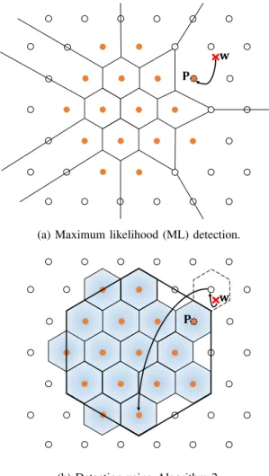
(a) Maximum likelihood (ML) detection.
𝐏 𝐰
(b) Detection using Algorithm 2.
Fig. 2: Detection methods in the receiver.
to a point in RN with few comparisons which depends on
the number of dimensions regardless of the infinite number of lattice points. The CPA independence from the number of lattice points is one of the most important advantages of using lattice-based geometrically shaped constellations compared to other shaping methods.
D. The constellation shift vector
In order to find the best shift vector to minimize the constellation energy, an iterative algorithm was sug-gested in [25] which can converge in a few iterations,
an+1= (1/M)Px∈CΛ(r,an)x. However, if M is very large,
as for some constellations in this paper (see Table II), then the sum cannot be exactly calculated, and if the sum is replaced by a Monte-Carlo approximation, then the algorithm is not guaranteed to converge.
In Fig. 3, we show that when the number of constellation points increases, we can ignore the optimization of finding the best shift vector, i.e., for large constellations, choosing any shift vector will give almost the same constellation energy as optimizing it. To show this concept, we define
µ:=Ea0[|Es,0−Es,opt|/Es,opt]whereEa0 stands for
expec-tation with respect to choosing a0 uniformly in V(0), Es,0
is the constellation energy using a random a0, and Es,opt is
Fig. 3: Effect of random selection of the shift vector on the constellation energy.
the constellation energy optimized by the iterative algorithm in [25] initialized with a0. Figure 3 shows that µ decreases
as the number of constellation points increases. Therefore, in constellations taken from the Leech lattice and E8 lattice
with SE of 8 bits/sym/dimension pair, where generating all constellation points is not feasible, we choose a random shift vector a in V(0). In this case, the effect of constellation average offset is negligible on the constellation energy, as shown in Fig. 3. However, for other constellations in this paper, the proposed algorithm in [25] witha0=0is applied and will
always result in a zero-mean constellation.
IV. FIGURES OF MERIT
In this section, parameters to study and compare different multidimensional modulation formats are introduced.
1) Spectral efficiency: For a constellation withM separate symbols inN dimensions, the SE is calculated as
SE =log2M
N/2 = 2 log2r (4)
and has the unit of bits per symbol per dimension pair. In fiber-optic communication, usually, the polarization of light is considered as a pair of dimensions because each polariza-tion can support two dimensions of in-phase and quadrature components. If sinc pulse shaping is used, the unit of SE can also be considered asbits per second per Hertzwhich shows how efficient the frequency spectrum is being used [33].
Based on Eq. (4), the SE is related to the scaling factor (r) of the Voronoi region. This shows that any SEs can be achieved by changing r for every lattice Λ. In this work, to simplify bit mapping, we focus on scaling factors that are powers of 2, i.e.,r= 2,4,8,16.
2) Symbol and bit error rate: For equiprobable constella-tions with ML estimation, using pairwise error probability and union bound, the symbol error rate (SER) is bounded by
SER≤ 1 M M−1 X i=0 X j6=i 1 2erfc d ij 2√N0 (5)
where dij is the Euclidean distance between ci and cj. For
high SNR, the terms with dij = dmin dominate, and for
lattices, all constellation points have at least one neighbor at distance dmin [34, chap. 5]. Therefore, the SER is bounded
by 1 2erfc d min 2√N0 ≤SER≤e ¯ τ 2erfc d min 2√N0 (6)
which≤e means an approximate upper bound that approaches the true value asN0 goes to zero. Also,τ¯= (1/M)P
M−1 i=0 τi
whichτiis the number of neighbours at the minimum distance
from symbolci. Equation (6) shows that two important factors
for SER of lattices aredmin and average of number of closest
neighbors which for high-dimensional lattices can be very high [34, chap. 5].
The BER depends on the bit labeling of the symbols as well. For dense packing high dimensional lattices, there is no Gray mapping solution to optimize the BER performance. In this paper, instead of looking for the best bit mapping, we looked at two fast and low-complexity methods which we call nat-ural binary and quasi-Gray constellation bit labeling. Natnat-ural binary labeling is the direct transformation of the symbol index (K) to its base-2 representation. Quasi-Gray labeling means transforming the symbol indexes in each dimension (ki) to a
binary Gray code.
3) Sensitivity penalty: For every modulation format,
dmin is the minimum Euclidean distance between two
symbols of the constellation. For high SNR and the AWGN channel, the probability of symbol error can be approximated using the union bound and its dominant terms which are proportional to erfc(dmin/(2
√
N0)) where
erfc(x) = (2/√π)R∞
x exp (−t
2)dt is the complementary
er-ror function and N0/2 is the variance of the Gaussian noise
in each dimension. Therefore, the SER is a monotonically decreasing function of d2min 4N0 = P RbN0 γ= Eb N0 γ (7) where γ = d2
min/(4Eb) is defined as the asymptotic power
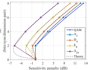
efficiency because for a given SER, the required power is pro-portional to 1/γ. The parameterγ describes the constellation geometry and is often given in dB. If different modulation formats are compared at the same power and bit rate,γshows the power gain for high SNR with respect to BPSK, QPSK and dual polarization QPSK modulation formats because for these constellations γ= 0 dB. The sensitivity penalty is also defined as1/γand it shows the performance penalty compared to BPSK, QPSK and dual polarization QPSK for high SNR [14]. The sensitivity penalty comparison of different VCs with respect to QAM are shown in Fig. 4.
Fig. 4: The SE vs. sensitivity penalty for lattice base multidi-mensional modulation formats. The dashed lines are calculated using Eq. (23) in [14].
TABLE I: Shaping and coding gains of multidimensional lattices [24], [34, chap. 5]
Lattice ZN A2 D4 E8 Λ24
γc(dB) 0 0.62 1.51 3.01 6.02
γs(dB) 0 0.17 0.37 0.65 1.03
For multidimensional modulation formats, as the SE in-creases, the asymptotic power efficiency (γ) becomes propor-tional to the product of two important gains over the cubic lattice called the shaping gain (γs) and coding gain (γc)
[11]. Shaping gain shows how spherical the boundary of the constellation is, and in this work, we use a Voronoi cut. The coding gain indicates the density of the lattice points. These gains for different lattices are shown in Table I and their mathematical definitions were presented in [11].
V. RESULTS
In this section, we present the simulation results applying the VCs in the AWGN and nonlinear fiber channel. The results are shown as the performance of these modulations in terms of uncoded BER and SER.
A. Additive white Gaussian noise channel
In this part, the bit labeling methods, detection algo-rithms in the receiver, and the performance of the VCs with Algorithms 1 and 2 are compared over the AWGN channel with respect to the equivalent QAM formats with ML detec-tion.
To compare the natural binary and quasi-Gray constellation bit labeling, we simulate their BER performance over the AWGN channel and use them to encode and decode the transmitted and received VC symbols. The simulation setup includes a transmitter which generates multidimensional sym-bols and a multidimensional AWGN channelN(0,N0
2 IN×N).
Natural binary Quasi-Gray
SE = 2 4 6 8
Fig. 5: Natural binary vs. quasi-Gray bit labeling for Leech lattice at different SEs over AWGN channel.
symbols. At a SE = 2 bits/sym/dimension pair, these two methods create the same symbol labeling for the constellation points. However, for higher SEs, quasi-Gray performs better as shown in Fig. 5 for the Leech lattice (Λ24).
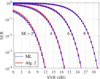
In the receiver, an alternative detection scheme for VCs is the ML estimation which is the optimum detection rule for constellations with uniform probability distribution of sym-bols. The ML estimation compares the received information with all possible constellation points and finds the one which has the minimum Euclidean distance from the received point. The ML estimation requires a lookup table the size of the constellation cardinality. Therefore, for our VCs, ML detection can be extremely time consuming for the constellation sizes shown in Table II. However, the fast and low-complexity per-formance of Algorithm 2 comes at the expense of suboptimal behaviour, which is illustrated in Fig. 2 and 6.
In Fig. 2a, the decision regions for the ML estimation are shown. If point P is transmitted and w is received, since it is still in the decision region of point P, it will be detected correctly. However, in Fig. 2b, using Algorithm 2, the received point will be mapped to an incorrect constellation point. This situation only happens when the received vector w is outside the Voronoi region of the transmitted vector (V(P)) and also outside the scaled Voronoi region (Vr). Therefore, when the
number of constellation points increases, the ratio between the boundary constellation points and the total number of points decreases, and these errors will be less likely. Also, in high SNR regimes, the received points are more probable to remain
TABLE II: Constellation size (M) in different dimensions and SEs SE 2 4 6 8 A2 4 16 64 256 D4 16 256 4,096 65,536 E8 256 65,536 16,777,216 4,294,967,296 Λ24 16,777,216 ≈2.8×10¹⁴ ≈4.7×10²¹ ≈7.9×1028 ML Alg. 2 SE = 2 4 6 8
Fig. 6: The ML estimation vs. Algorithm 2 performance for QAM formats at different SEs over AWGN channel.
in the Voronoi region of their transmitted points therefore Algorithm 2 is able to detect them correctly similar to the ML estimation.
In Fig. 6, the ML estimation and Algorithm 2 are compared for QAM formats in different SEs over AWGN channel. Interestingly, as the SNR (defined as Es/(N·N0/2)) or the
number of the constellation points increases, the gap between the SER performance of Algorithm 2 and the ML estimation decreases and they approach each other. Therefore, it can be concluded that, for finite VCs, Algorithm 2 is close to optimum for constellations with high cardinality, or in the limit of high SNR.
Finally, in Fig. 7, the BER performance of VCs in dif-ferent dimensions are compared with the equivalent QAM format at the same SE. Except for the A2 lattice in Fig. 7a,
all VCs will eventually perform better than the QAM for-mat as the Eb/N0 increases. The reason for this behavior
is the asymptotic power efficiency that was discussed in section IV. However, for low Eb/N0, QAM formats
outper-form VCs because of Gray labeling and smaller¯τ. In Fig. 4, at
SE = 2 bits/sym/dimension pair, theA2and the QAM format
have the same sensitivity penalty, however, in Fig. 7a, 4-QAM always performs better thanA2in allEb/N0. This is because
of 4-QAM Gray labeling and the average number of closest neighbors which for theA2lattice with 4 constellation points
isτ¯= 2.5 and for the 4-QAM isτ¯= 2.
B. Nonlinear optical channel
An important characteristic of the VCs is their performance in the nonlinear fiber-optic channel. In order to investigate this problem, a nonlinear fiber-optic channel has been simulated using the split-step Fourier method (SSFM). In an experimen-tal setup, multidimensional modulation formats can be realized in different ways. Among the possible dimensions in fiber, in this work, we focus on in-phase, quadrature, polarization, and wavelength. Using different combinations of dimensions, e.g.,
2.26 × 10⁻⁴
(a)SE = 2 bits/sym/dimension pair
2.26 × 10⁻⁴ (b)SE= 4 bits/sym/dimension pair 2.26 × 10⁻⁴ (c)SE = 6 bits/sym/dimension pair 2.26 × 10⁻⁴ (d)SE= 8 bits/sym/dimension pair
Fig. 7: The BER vs.Eb/N0 for multidimensional modulation formats over AWGN channel
time slots, wavelengths, spatial modes, in practice will give different performance results because the coupling and cross-talk between the dimensions in a nonlinear channel might differ. In the wavelength-division multiplexing (WDM) sys-tem considered in this paper, multiple synchronized coherent receivers are needed to detect each channel. Another design could possibly include time slots as additional dimensions which will reduce the number of coherent receivers and the nonlinear interaction of channels.
The simulation setup consists of a transmitter side including a symbol generator that produces multidimensional symbols according to the selected VC. These symbols are then paral-lelized into multiple groups of 4-dimensional symbols because each wavelength can carry up to 4 dimensions in a single-mode fiber. At this stage, each group of 4-dimensional symbols is combined with pilot symbols that have QPSK modulation format and they are used for pilot-aided digital signal process-ing in the receiver. Finally, in the transmitter, the combined payloads and pilots are upsampled and filtered with a
root-raised-cosine (RRC) filter. Then, each group is shifted to its corresponding wavelength and they are added together to form a WDM system. Before the channel, the total optical power of the signal is set and then using the Manakov equations [35] and SSFM [36, chap. 2], the signal is propagated over the nonlinear dispersive fiber-optic channel. The signal is amplified using an erbium-doped fiber amplifier (EDFA) at the end of each span in the fiber link. In our simulations, uniform QAM constellations over multiple wavelengths and polarizations are considered as benchmarks to compare the transmission performance with VCs at the same SE.
On the receiver side, first, digital dispersion compensation is applied for the whole propagation link distance. Nonlinearity-compensation methods, such as digital backpropagation, are not performed in the receiver; however, they can improve the performance of the constellations by compensating the fiber impairments at the cost of increased complexity. Then, each wavelength channel is filtered out using an RRC filter and downsampled. Using the QPSK pilots, polarization
de-2.26 × 10⁻⁴
3 dB
Fig. 8: The BER vs. total transmitted optical power after 80 spans of 80 km fibers over a WDM system with 6 wavelengths.
TABLE III: Nonlinear simulation setup parameters
Parameter Value
Symbol rate 28 GBaud
RRC roll-off factor 0.2
WDM spacing 50 GHz
Fiber nonlinear coefficient 1.3W−1km−1 Fiber dispersion 17 ps/nm/km
Fiber attenuation 0.2 dB/km
Span length 80 km
EDFA noise figure 5 dB
SSFM step size 0.5 km
Oversampling factor 32
Pilot overhead 1.56%
multiplexing and phase tracking are applied to the payload symbols. After that, the processed payloads are combined together to form the multidimensional symbols again and using Algorithm 2 and ML estimation, it is decided what the transmitted symbol has been for VCs and QAM format, respectively. In the end, BER is calculated based on the trans-mitted and the received bits. The parameters of the nonlinear simulation setup are listed in Table III.
In Fig. 8, the BER performance of the Leech lattice is compared with the 4-QAM at the same SE. The total propa-gation distance is 80 spans (6400 km) using 6 wavelengths to transmit the 24-dimensional signals. At a BER of2.26×10−4, which corresponds to 10−15 after error correction using a Reed-Solomon (544, 514) (KP4) code [37], the achieved transmitted power gain is more than 3 dB.
In Fig. 9, the BER performance is shown at the optimum power in different transmission distances. According to our simulations, the optimum power almost remains constant at different transmission distances. In this representation, trans-mission distance improvement of more than 30 spans or 38% is shown at a BER equal to 2.26×10⁻⁴.
Other shaping methods, e.g., probabilistic amplitude shap-ing, offer around 7 to 15% reach improvement at a given achievable information rate, compared with uniform QAM [7], [38], [39]. However, some caution is advised when comparing
2.26 × 10⁻⁴
30 spans
Fig. 9: The BER vs. transmission distance at the optimum optical power over nonlinear fiber-optic channel.
reach gains obtained using different performance metrics. For example, the SER and BER benefit from both coding gain and shaping gain, whereas information rates typically reflect shap-ing gain only. Nevertheless, it seems clear that our geometric shaping method can be considered as a competitive shaping approach with low complexity to increase the performance of optical communication systems.
Future work may include a more detailed comparison with probabilistic shaping, as well as trellis shaping [27], [28]. Also, combinations of VC and hard-decision forward error correction codes can be investigated in low latency and low power consumption applications, e.g., video conferencing or instrument control links that are latency sensitive.
VI. CONCLUSION
We have analyzed Voronoi constellations as a geometric shaping method for optical communication systems. The com-plexity of modulation and demodulation are low compared with other geometric schemes because modulation and demod-ulation are carried out algorithmically and the constellation need not be stored in a table, paving the way for more or less unlimited cardinalities. Reach enhancements as high as 38% is found in nonlinear fiber link simulations. We conclude that lattice-based geometric shaping can provide higher gains than what has been reported using probabilistic shaping, at much shorter block lengths and moderate complexity.
VII. ACKNOWLEDGMENT
We wish to acknowledge financial support from the Knut and Alice Wallenberg foundation as well as the Swedish Re-search Council (VR) in projects 2017-03702 and 2019-04078. The simulations were performed on resources at Chalmers Centre for Computational Science and Engineering (C3SE) provided by the Swedish National Infrastructure for Comput-ing (SNIC).
REFERENCES
[1] P. J. Winzer, “High-spectral-efficiency optical modulation formats,” Journal of Lightwave Technology, vol. 30, no. 24, pp. 3824–3835, 2012. [2] P. J. Winzer, D. T. Neilson, and A. R. Chraplyvy, “Fiber-optic trans-mission and networking: the previous 20 and the next 20 years,”Optics Express, vol. 26, no. 18, pp. 24 190–24 239, 2018.
[3] M. Seimetz, High-Order Modulation for Optical Fiber Transmission. Springer, 2009, vol. 143.
[4] F. R. Kschischang and S. Pasupathy, “Optimal nonuniform signaling for Gaussian channels,”IEEE Transactions on Information Theory, vol. 39, no. 3, pp. 913–929, 1993.
[5] G. D. Forney, Jr., R. G. Gallager, G. R. Lang, F. M. Longstaff, and S. U. Qureshi, “Efficient modulation for band-limited channels,”IEEE Journal on Selected Areas in Communications, vol. 2, no. 5, pp. 632–647, 1984. [6] J. Cho and P. J. Winzer, “Probabilistic constellation shaping for optical fiber communications,”Journal of Lightwave Technology, vol. 37, no. 6, pp. 1590–1607, 2019.
[7] T. Fehenberger, A. Alvarado, G. B¨ocherer, and N. Hanik, “On proba-bilistic shaping of quadrature amplitude modulation for the nonlinear fiber channel,”Journal of Lightwave Technology, vol. 34, no. 21, pp. 5063–5073, 2016.
[8] B. Chen, C. Okonkwo, H. Hafermann, and A. Alvarado, “Polarization-ring-switching for nonlinearity-tolerant geometrically shaped four-dimensional formats maximizing generalized mutual information,” Jour-nal of Lightwave Technology, vol. 37, no. 14, pp. 3579–3591, 2019. [9] R. T. Jones, T. A. Eriksson, M. P. Yankov, and D. Zibar, “Deep learning
of geometric constellation shaping including fiber nonlinearities,” in European Conference on Optical Communication (ECOC), 2018. [10] A. A. El-Rahman and J. Cartledge, “Multidimensional geometric
shap-ing for QAM constellations,” in European Conference on Optical Communication (ECOC), 2017.
[11] G. D. Forney, Jr. and L.-F. Wei, “Multidimensional constellations-Part I: Introduction, figures of merit, and generalized cross constellations,” IEEE Journal on Selected Areas in Communications, vol. 7, no. 6, pp. 877–892, 1989.
[12] M. Karlsson and E. Agrell, “Four-dimensional optimized constellations for coherent optical transmission systems,” inEuropean Conference on Optical Communication (ECOC), 2010.
[13] E. Ip, A. P. T. Lau, D. J. Barros, and J. M. Kahn, “Coherent detection in optical fiber systems,”Optics Express, vol. 16, no. 2, pp. 753–791, 2008.
[14] E. Agrell and M. Karlsson, “Power-efficient modulation formats in co-herent transmission systems,”Journal of Lightwave Technology, vol. 27, no. 22, pp. 5115–5126, 2009.
[15] M. Karlsson and E. Agrell, “Power-efficient modulation schemes,” in Impact of Nonlinearities on Fiber Optic Communications. Springer, 2011, pp. 219–252.
[16] T. Koike-Akino, D. S. Millar, K. Kojima, and K. Parsons, “Eight-dimensional modulation for coherent optical communications,” in Euro-pean Conference on Optical Communication (ECOC), 2013.
[17] T. Koike-Akino and V. Tarokh, “Sphere packing optimization and EXIT chart analysis for multi-dimensional QAM signaling,” inIEEE International Conference on Communications (ICC), 2009.
[18] T. A. Eriksson, P. Johannisson, E. Agrell, P. A. Andrekson, and M. Karlsson, “Biorthogonal modulation in 8 dimensions experimentally implemented as 2PPM-PS-QPSK,” in Optical Fiber Communication Conference (OFC), 2014.
[19] X. Lu, A. Tatarczak, V. Lyubopytov, and I. Tafur Monroy, “Optimized eight-dimensional lattice modulation format for IM-DD 56 Gb/s optical interconnections using 850 nm VCSELs,”Journal of Lightwave Tech-nology, vol. 35, no. 8, pp. 1407–1414, 2017.
[20] X. Lu, V. S. Lyubopytov, and I. Tafur Monroy, “24-dimensional mod-ulation formats for 100 Gbit/s IM-DD transmission systems using 850 nm single-mode VCSEL,” in European Conference on Optical Communication (ECOC), 2017.
[21] D. S. Millar, T. Koike-Akino, S. ¨O. Arık, K. Kojima, K. Parsons, T. Yoshida, and T. Sugihara, “High-dimensional modulation for coherent optical communications systems,”Optics Express, vol. 22, no. 7, pp. 8798–8812, 2014.
[22] T. Matsumine, T. Koike-Akino, D. S. Millar, K. Kojima, and K. Parsons, “Short lattice-based shaping approach exploiting non-binary coded mod-ulation,” inEuropean Conference on Optical Communication (ECOC), 2019.
[23] A. Shiner, M. Reimer, A. Borowiec, S. O. Gharan, J. Gaudette, P. Mehta, D. Charlton, K. Roberts, and M. O’Sullivan, “Demonstration of an 8-dimensional modulation format with reduced inter-channel nonlinearities
in a polarization multiplexed coherent system,”Optics Express, vol. 22, no. 17, pp. 20 366–20 374, 2014.
[24] G. D. Forney, Jr., “Multidimensional constellations-Part II. Voronoi constellations,” IEEE Journal on Selected Areas in Communications, vol. 7, no. 6, pp. 941–958, 1989.
[25] J. Conway and N. Sloane, “A fast encoding method for lattice codes and quantizers,”IEEE Transactions on Information Theory, vol. 29, no. 6, pp. 820–824, 1983.
[26] ——, “Fast quantizing and decoding and algorithms for lattice quantizers and codes,”IEEE Transactions on Information Theory, vol. 28, no. 2, pp. 227–232, 1982.
[27] B. P. Smith and F. R. Kschischang, “A pragmatic coded modulation scheme for high-spectral-efficiency fiber-optic communications,” Jour-nal of Lightwave Technology, vol. 30, no. 13, pp. 2047–2053, 2012. [28] G. D. Forney, Jr., “Trellis shaping,”IEEE Transactions on Information
Theory, vol. 38, no. 2, pp. 281–300, 1992.
[29] M. Karlsson and E. Agrell, “Spectrally efficient four-dimensional mod-ulation,” inOptical Fiber Communications Conference (OFC), 2012. [30] J. H. Conway and N. J. A. Sloane,Sphere Packings, Lattices and Groups,
3rd ed. Springer, 1999.
[31] J. H. Conway and N. J. Sloane, “On the Voronoi regions of certain lattices,” SIAM Journal on Algebraic Discrete Methods, vol. 5, no. 3, pp. 294–305, 1984.
[32] J.-P. Adoul and M. Barth, “Nearest neighbor algorithm for spherical codes from the Leech lattice,”IEEE Transactions on Information Theory, vol. 34, no. 5, pp. 1188–1202, 1988.
[33] M. Karlsson and E. Agrell, “Multidimensional Modulation and Coding in Optical Transport,”Journal of Lightwave Technology, vol. 35, no. 4, pp. 876–884, 2016.
[34] S. Benedetto and E. Biglieri,Principles of Digital Transmission: with Wireless Applications. Springer, 1999.
[35] S. Mumtaz, R.-J. Essiambre, and G. P. Agrawal, “Nonlinear propagation in multimode and multicore fibers: Generalization of the Manakov equations,”Journal of Lightwave Technology, vol. 31, no. 3, pp. 398– 406, 2012.
[36] G. P. Agrawal,Nonlinear Fiber Optics, 5th ed. Springer, 2013. [37] E. Agrell and M. Secondini, “Information-theoretic tools for optical
communications engineers,” inIEEE Photonics Conference (IPC), 2018. [38] C. Pan and F. R. Kschischang, “Probabilistic 16-QAM shaping in WDM systems,”Journal of Lightwave Technology, vol. 34, no. 18, pp. 4285– 4292, 2016.
[39] T. Fehenberger, G. B¨ocherer, A. Alvarado, and N. Hanik, “LDPC coded modulation with probabilistic shaping for optical fiber systems,” in Optical Fiber Communication Conference (OFC), 2015.
![Fig. 1: Properties for A 2 lattice. The vectors g 1 = [1 0] T and g 2 = [1/2 √](https://thumb-us.123doks.com/thumbv2/123dok_us/718845.2589881/3.918.513.805.89.360/fig-properties-lattice-vectors-g-t-g.webp)