7
Voltage and Current
Harmonics – Case Study
Angelo Baggini and Zbigniew Hanzelka
C7.1 SELECTION AND RATING OF TRANSFORMERS FOR
A SIX-PULSE CONVERTER [10]
When the harmonic spectrum is known, or at least can be measured with a certain reliability or predicted, the additional losses can be easily calculated.
The process of calculation should be made through the following steps:
1. Determination of all the components of additional losses due to the presence of harmonics. 2. Determination of the harmonic spectrum, either by measurement or by estimation, taking
into account all harmonic generating equipment, in particular electronic converters. 3. Calculation of the contribution of each harmonic component and determination of total
additional losses.
In practice, it is important to use the real harmonic current magnitudes rather than theoretical values.
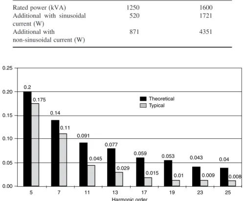
Table C7.1 shows the calculated additional losses, for harmonic currents up to order 25, for two transformers at normal environmental temperature, assuming the current harmonic spectrum illustrated in Figure C7.1.
Handbook of Power Quality Edited by Angelo Baggini © 2008 John Wiley & Sons, Ltd
G
46Table C7.1 Additional losses calculated in the presence of non-sinusoidal
currents
Loss type First transformer Second transformer
(215C) (228C)
Rated power (kVA) 1250 1600
Additional with sinusoidal current (W) 520 1721 Additional with non-sinusoidal current (W) 871 4351 0.25 0.2 Theoretical Typical 0.175 0.14 0.11 0.091 0.077 0.045 0.029 0.059 0.053 0.043 0.04 0.008 0.009 0.01 0.015 0.20 0.15 0.10 0.05 0.00 5 7 11 13 17 19 23 25 Harmonic order
Figure C7.1 Theoretical and actual values of current harmonics for a six-pulse converter (in pu)
The results demonstrate that the transformer characteristics play an important role in determining the losses with harmonic loads.
The transformers in this example were measured at slightly different temperatures
(215C for the first and 228C for the second); this will not change the reliability of results.
C7.1.1 Calculation of the
K
Factor
Table C7.2 shows the calculation of theKfactor for the harmonic spectrum of Figure C7.1
on a per unit basis.
The first step is the calculation of the r.m.s. value of total current I, 1.0410 in this
case, after which the squares of the proportionate values of each harmonic current can be
calculated, leading to the value of K. For such a load, a transformer with a K rating of 9
G
47Table C7.2 Reduction factors for current harmonics
Harmonic order Ih/I1 Ih/I12 Ih/I Ih/I2 Ih/I2×h2 1 1000 10000 09606 09227 09227 5 0200 00400 01921 00369 09227 7 0140 00196 01345 00181 08862 11 0091 00083 00874 00076 09246 13 0077 00059 00740 00055 09246 17 0058 00034 00557 00031 08971 19 0056 00031 00538 00029 10446 23 0043 00018 00413 00017 09025 25 0040 00016 00384 00015 09227 Sum= 10838 83476 Total (r.m.s.)= 10410 Kfactor= 83476
C7.1.2 Calculation of the Factor
K
The first step in establishing factorK(Table C7.2) is to discover the value ofe, the ratio of
eddy current loss to total load loss at fundamental frequency. The transformer manufacturer should be able to provide this, otherwise it is likely to lie in the range of 0.05 to 0.1. The
exponent q depends critically on the construction of the transformer and should also be
Table C7.3 Reduction factors for current harmonics
Harmonic order Ih/I1 Ih/I12 h I h/I2×h2 1000 10000 10000 10000 0200 00400 154258 06170 0140 00196 273317 05357 0091 00083 589342 04880 0077 00059 782895 04642 0058 00034 1235274 04155 0056 00031 1492386 04680 0043 00018 2065082 03818 0040 00016 2379567 03807 Sum= 10838 [a]= 47511 Total (r.m.s.)= 10410 a×I1/I2= 43839 e/e+1= 0091 I1/I2= 09227 K2= 13985 K= 118
G
48available from the manufacturer. It is likely to lie in the range 1.5 to 1.7. As before, the calculations are based on the theoretical values from Figure C7.1. In practice, the transformer would need to be derated to 84.75 % (1/1.18) of nominal power rating when supplying a six-pulse converter.
C7.2 DERATING CABLES
As described in Section 7.6.2, the current amplitude in the neutral due to the third harmonic could exceed in amplitude the phase current at the fundamental frequency. In this case the neutral current should be considered with regard to the sizing of the circuit cables. This example is related to an office building where four different harmonics spectra have been used to evaluate the cable size to be installed.
The system is a three-phase circuit with a 32 A rated load to be installed using a four-core EPR insulated cable laid directly onto the wall.
C7.2.1 Scenarios
These are as follows:
1. Absence of harmonics. For this current it is common practice to use a copper conductor
cable with a 4 mm2cross-section with a capacity of 35 A [5] .
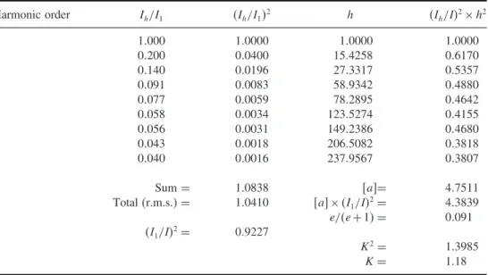
2. A value of 22 % of the third-order harmonic (Figure C7.2). For this spectrum the neutral
current will beIN =32·022·3=211 A,IN< IF, so the value is selected on the basis
of the line current. Applying a 0.86 reduction factor (Table 7.12), the equivalent load
current is 32/086=372 A. For this value the cable section has a 6 mm2cross-section
with a capacity of 44 A [5].
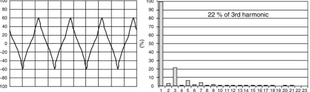
For a value of 42 % of the third-order harmonic (Figure C7.3), IN =32·042·
3=40.3 A,IN> IF, so the value is selected on the basis of the neutral current. Applying
a 0.86 reduction factor, the equivalent load current is 403/086=469 A. For this value
the cable section has a 10 mm2 cross-section with a capacity of 60 A [5].
0 1 2 3 4 5 6 7 8 9 22 % of 3rd harmonic 10 11 12 13 14 15 16 17 18 19 20 21 22 23 10 20 30 40 50 (%) 60 70 80 90 100 –100 –80 –60 –40 –20 0 20 40 60 80 100
G
49 –100 –80 –60 –40 –20 0 20 40 60 80 100 100 42% of 3rd harmonic 90 80 70 60 50 % 40 30 20 10 0 1 2 3 4 5 6 7 8 9 1011121314151617181920212223Figure C7.3 Current waveform and its spectrum
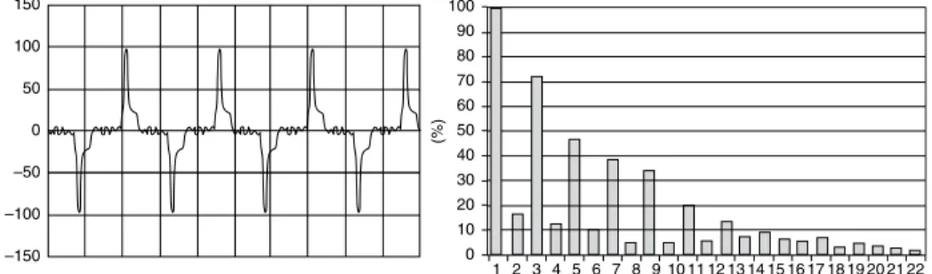
–150 0 1 2 3 4 5 6 7 8 9 10 11 12 13 14 15 16 17 18 19 20 21 22 10 20 30 40 50 (%) 60 70 80 90 100 –100 –50 0 50 100 150
Figure C7.4 Current waveform and its spectrum
3. Third-order, harmonic-rich environment, as in Figure C7.4. The neutral current will
be IN=32·131·3=12576 A, IN> IF, so the value is selected on the basis of the
neutral current. Applying a reduction factor equal to 1, the equivalent load current is
12576/1=12567 A. For this value the cable section has a 35 mm2cross-section with
a capacity of 128 A [5].
C7.3 HARMONIC SOURCE LOCATION
In the event of significant distortion of the supply network voltage at the PCC between the electricity supplier and customer, the source of disturbance should be located. This becomes of particular significance when formulating contracts for electric power supply or charging for worsening the quality of supply. In many cases also a quantitative determination of the supplier and customer(s) contribution to the total voltage distortion at the PCC is required.
G
50Supply system Load
Measuring point P(n)=U(n)I(n) cos(Θu(n)–Θi(n))
P(n)≥0
P(n)<0
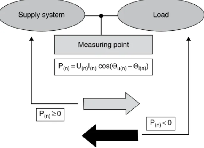
Figure C7.5 The principle of locating thenth harmonic source on the basis of its active
power measurement
The most common practical method for locating harmonic sources is based on deter-mining the direction of active power flow for given harmonics, though many authors indicate its limitations and propose others methods (investigation of the direction of reac-tive power flow and the ‘critical impedance’, interharmonic injection, determining voltage and current relative values, etc. [34],[35]). In most cases these methods, apart from their technical complexity, require precise information on values of equivalent parameters of the analyzed system, which are difficult to access, or can only be obtained as a result of costly measurements.
According to the direction of active power flow method, the dominant source of a
given harmonic (of order n) can be located by determining the direction of this harmonic
active power flow at various points of the system (Figure C7.5). A non-zero value of
Pn=UnIncosun−inis the effect of the interaction of voltage and current with the
same frequency. A linear load supplied with distorted voltage draws active power for each
harmonic:Pn≥0. If non-linear elements exist at the customer side, the active power for
some harmonics can be supplied to the network:Pn<0. The sign ofPncan be determined
by means of measuring the phase angles of the voltage and current of the same order:un
andin.
The principle of this method is explained in the example of a single-phase
circuit, shown in Table C7.4 (the supply voltage source is US, LS, where the
non-linear load is the thyristor power controller (TYR1, TYR2, resistance RONL,
induc-tance LONL, which is the source of harmonic currents of order n=2k ± 1 =3, 5,
7, 9, 11, 13, 15, (for k=123 ). There cases, distinguished by location of the
voltage distortion source, are discussed for the power controller located: (i) upstream of the PCC, (ii) downstream of the PCC, and (iii) harmonic sources at both sides of the PCC.
Table C7.4 Example simulations illustrating the method for harmonic source location based on the active power measurement Model of the electric power network with harmonic source Waveforms of voltage UPCC and current IPCC Active powers of individual harmonics Harmonic source at the supplier’s side Active powers of individual harmonics have a positive sign. The supplier is responsible for the voltage waveform distortion. US UPCC ROL IPCC LOL LS LS IS PCC
IONL RONL LONL
TYR2 TYR1 UPCC IPCC 130 140 150 160 170 Time (s) U in Volts –120 120 240 0 –240 –20 –10 0 10 20 I in Amps 1 34 5 6 7 8 9 10 11 12 13 14 15 n n 1.4 100 90 80 70 60 50 40 30 20 10 0 1.2 1.0 2 13 4 56 78 9 10 11 12 13 14 15 2 0.0 0.4 0.8 0.6 0.2 P (n) (%) P (n) (%) Harmonic source at customer’s side Active powers of given harmonics have a negative sign. The customer is responsible for the voltage waveform distortion. US UPCC ROL IPCC LOL LS LS IS PCC IOL RONL LONL TYR2 TYR1 UPCC IPCC 130 140 150 160 170 Time (s) U in Volts –12.0 12.0 24.0 0 –24.0 –8.0 –4.0 4.0 0.0 8.0 I in Amps n 1 03 4 5 67 8 91 0 1 1 12 13 14 15 2 n 1 56789 1 0 1 1 1 2 1 3 1 4 1 5 1.0 0.5 0.0 –0.5 –1.0 –1.5 –2.0 –2.5 –3.0 –3.5 –4.0 –4.5 –5.0 100 90 80 70 60 50 40 30 10 –10 20 0 P (n) (%) P (n) (%) 24 3
Table C7.4 (Continued) Model of the electric power network with harmonic source Waveforms of voltage UPCC and current IPCC Active powers of individual harmonics Harmonic source at both the customer’s and supplier’s side Depending on the control angle of thyristor switches, one of the parties, either the supplier or the customer, will be the dominant contributor to voltage distortion. US IPCC UPCC RONL1 RONL2 IONL1 LS IS LS PCC TYR4 TYR3 TYR1 TYR2 Load 1 Load 1 UPCC IPCC 130 140 150 160 170 Time (s) U in Volts –140 140 280 0 –280 –8.0 –4.0 4.0 0.0 8.0 I in Amperes n 1 3 4 5 6 7 8 9 10 11 12 13 14 15 2 n 1 3456 789 10 11 12 13 14 15 2 100 0.04 0.08 0.00 –0.04 –0.08 90 80 70 60 50 40 30 20 10 0 –10 P (n) (%) P (n) (%)
G
53BIBLIOGRAPHY
[1] Arrillaga J., Watson N. R., Chen S.,Power system quality assessment, John Wiley & Sons, Ltd,
Chichester, 2000.
[2] Arsenau R., Filipski P. S., Zelle J., A VA-meter-error analyzer.IEEE Transactions on Power
Delivery, vol. 6, no. 4, 1991.
[3] Baggini A., Zanoli F., Progetto di trasformatori per l’alimentazione di azionamenti e carichi non lineari. VIII Seminario Interattivo su Azionamenti elettrici innovazioni tecnologiche e problem-atiche emergenti, Bressanone (BZ), 10–12 marzo 1997.
[4] CEI 14-4/1983,Trasformatori di potenza.
[5] CEI UNEL 35024/1,Cavi elettrici isolati con materiale elastomerico o termoplastico per tensioni
nominali non superiori a 1000 V in corrente alternata e 1500 V in corrente continua. Portate di corrente in regime permanente per posa in aria, 1997.
[6] Chapman D., Harmonics – causes and effects.Leonardo Power Quality Application Guide –
Part 3.1, 2001.
[7] Correggiari F.,Costruzione di macchine elettriche, Cisalpino Goliardica, Milan.
[8] Datta S. K., Nafsi A., Distribution relay performance under harmonics conditions. PQA’92, Atlanta, Georgia, USA, 1992.
[9] Desmet J., Baggini A., Harmonics – neutral sizing in harmonic rich installations. Leonardo
Power Quality Application Guide – Part 3.5.1, 2003.
[10] Desmet J., Delaere G., Harmonics – selection and rating of transformers.Leonardo Power Quality
Application Guide – Part 3.5.2, 2005.
[11] Elmore W. A., Kramer C. A., Zocholl E., Effect of waveform distortion on protective relays. IEEE Transactions on Industry Applications, vol. 29, no. 2, 1993.
[12] EN 50160,Voltage characteristics of electricity supplied by public distribution systems.
[13] Fassbinder S., Harmonics – passive filters.Leonardo Power Quality Application Guide – Part
3.3.1, 2003.
[14] Girgis A. A., Nims J. W., Jacomino J., Dalton J. G., Bishop A., Effect of voltage harmonics
on the operation of solid-state relays in industrial applications.IEEE Transactions on Industry
Applications, vol. 28, vol. 5, 1992.
[15] Gruzs T. M., A survey of neutral currents in three-phase computer power systems.IEEE
Trans-action on Industry Applications,vol. 26, no. 4, 1990.
[16] Hanzelka Z., Bien A., Harmonics – interharmonics.Leonardo Power Quality Application Guide –
Part 3.3.1, 2004.
[17] IEC 60364–5-523,Electrical installations of buildings – Part 5-52: Selection and election of
electrical equipment – Wiring systems.
[18] IEC 61000-1-4,Historical rationale for the limitation of power-frequency conducted harmonic
current emissions from equipment in the frequency range up to 9 kHz, Technical Report.
[19] IEC 61000-2-1,Electromagnetic compatibility (EMC) Part 2-1: Environment – Description of
the environment: Electromagnetic environment for low-frequency conducted disturbances and signalling in public power supply systems, 1990.
[20] IEC 61000-2-2,Electromagnetic Compatibility (EMC) – Part 2-2: Environment – Compatibility
levels for low frequency conducted disturbances and signalling in public low-voltage power supply systems.
[21] IEC 61000-3-2,Limits for harmonic current emissions (equipment input current ≤ 16 A per
phase).
[22] IEC 61000-4-7,Electromagnetic compatibility (EMC) Part 4: Testing and measurement
tech-niques Section 7: General guide on harmonics and interharmonics measurements and instru-mentation for power supply systems and equipment connected thereto.
G
54[23] IEC TC 64 WG 2,Current-carrying capacity and related overcurrent protection, Revision of
section 523", September 1996.
[24] IEEE 519-92,IEEE Recommended Practices and Requirements for Harmonic Control in
Elec-trical Power Systems, 1992.
[25] IEEE 1159,Recommended practice for monitoring electric power quality.
[26] Karve S., Harmonics – active harmonic conditioners. Leonardo Power Quality Application
Guide – Part 3.3.3, 2001.
[27] Norma CEI 64-8/5,Impianti elettrici utilizzatori a tensione nominale non superiore a 1000 V
in corrente alternata e a 1500 V in corrente continua. Parte 5: Scelta ed installazione dei componenti elettrici, 1992.
[28] Power System Harmonics, Power Technologies, Inc., 1989.
[29] Purkayastha I., Savoce P. J., Effect of harmonics on power measurement.IEEE Transactions on
Industry Applications, vol. 26, no. 5, 1990.
[30] Shepherd W., Zakikhani P.,Energy flow and power factor in non-sinusoidal circuits, Cambridge
University Press, New York.
[31] Stade D., Shau H., Influence of voltage harmonics on single-phase earth fault currents. PQA’91. [32] Tsukamoto M., Kouda I. N., Minowa Y., Nishimura S., Advanced method to identify harmonics characteristic between utility grid and harmonic current sources. 8th International Conference on Harmonics and Quality of Power, Athens, Greece, 14–16 October, 1998.
[33] West K., Harmonics – true RMS – the only true measurement.Leonardo Power Quality
Appli-cation Guide – Part 3.2.2, 2001.
[34] Xu Wilsun, Liu Yilu, A method for determining customer and utility harmonic contributions at
the point of common coupling.IEEE Transactions on Power Delivery, vol.15, no.2, 2000.
[35] Xu Wilsun, Liu Xian, Liu Yilu, An investigation on the validity of power-direction method for
harmonic source determination.IEEE Transactions on Power Delivery, vol. 18, no. 1, 2003.
[36] Yacamini R., Chang S. C., Noise and vibration from induction machines fed from harmonic sources. Proceedings of IEEE ICHPS VI, Bologna, 21–23 September, 1994.
[37] ˙Ze˙zelenko I. W., Harmonics in power system supplying industrial loads, Elektroatomizdat,