WSN Link-layer Security Frameworks
Ioannis KRONTIRIS1, Tassos DIMITRIOU, Hamed SOROUSH and Mastooreh SALAJEGHEH
Athens Information Technology, Greece
Abstract.In this chapter we elaborate on the need for security frameworks at the link-layer and describe what services they provide to the upper layers. We review the proposed frameworks in the bibliography and discuss about their pros and cons. Then we present in more detail the design and implementation of one of them, the L3Sec framework, in order to show what issues arise in such a process and how
they can be solved. Some of these features include providing acceptable resistance against node capture attacks and replay attacks, as well as the run-time composi-tion of security services in a completely transparent way. The framework is able to satisfy its requirements based on an an efficient scalable post-distribution key management scheme, which we also present.
Keywords.Frameworks, Security Services, Link-layer security
Introduction
The different directions of ongoing research in WSNs are based on security challenges that address several classes of attacks and how sensor networks can defend against them. Another, more general approach to address security in WSNs can be on a per-layer basis, instead of a per-attack basis. Under this perspective, security protocols can be designed to provide security in a particular layer and cooperate with security protocols in other layers to compose a complete defence for the nodes and the network.
This layer based classification of security protocols can help towards a more clear understanding of WSN security and better protocol design. However, in practical sensor networks, such as those using the TinyOS platform, there does not exist a clear formal way for demarcating between the various layers. Nevertheless, one could break the net-work stack in TinyOS into four major layers: the physical layer, the link/MAC layer (in the remainder of this chapter we will refer to this simply as the link layer), the routing layer, and the application layer.
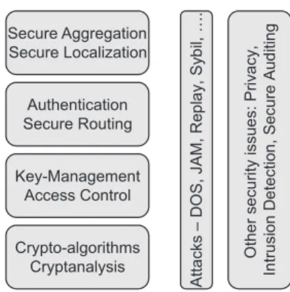
On this basis we could range security protocols in a corresponding layered taxon-omy, as shown in Figure 1 [1]. Protocols in higher layers use security services provided by lower layers or depend on their reliable functionality. There are also other security issues like intrusion detection that cannot be classified in this layered approach as they are more general problems that spam different layers. Currently, research on security solutions for WSNs has focused mainly in the following three categories:
1Corresponding Author: Ioannis Krontiris, Athens Information Technology, 19.5 Km Markopoulo Avenue,
Crypto-algorithms Cryptanalysis Key-Management Access Control Authentication Secure Routing Secure Aggregation Secure Localization A tt a ck s – D O S , JA M , R e p la y , S y b il, …. O th e r s e cu ri ty iss u e s: P ri v a c y , In tr u si o n D e te c ti o n , S e c u re A u d it in g
Figure 1. Sensor networks security map based on a layered approach.
1. Key management:A lot of work has been done [2] in establishing cryptographic keys between nodes to enable encryption and authentication. These protocols can be classified as link layer protocols.
2. Authentication and Secure Routing:Several protocols [3] have been proposed to protect information from being revealed to an unauthorized party and guarantee its integral delivery to the base station. These protocols clearly belong to the routing layer.
3. Secure services:Certain progress has been made in providing specialized secure services, like secure localization [4], secure aggregation [5] and secure time syn-chronization [6]. These services are closer to the application layer.
Historically speaking, research in WSN security first focused on key management, as it is the most basic requirement for providing further security services. Another area that attracted a lot of research work was secure routing, but the solutions given either targeted a specific routing protocol or confronted only a narrow class of attacks. Also a lot of effort has been made to provide specialized secure services, but as network and application protocols continued to flourish, security researchers realized that more general solutions were needed to address the diversity of these protocols. As a result, attention gradually turned to lower layers of the protocol stack, notably the link layer.
What makes link-layer security important is that end-to-end security mechanisms are not possible in sensor networks, so more transparent mechanisms provided by the link layer are needed. Protocols used in conventional networks for end-to-end security, such as SSH [7], SSL[8], or IPSec[9], even though they are feasible in constrained em-bedded devices [10], they are considered inappropriate since they don’t allow in-network processing and data aggregation which play an important role in energy-efficient data retrieval. These operations require the intermediate nodes to access and possibly modify the contents of packets, which would not be possible if an end-to-end security scheme was used.
In sensor networks it is also important to allow intermediate nodes to check message integrity and authenticity, or else the network would be prone to several denial of service attacks. Using an end-to-end security mechanism, packets would have to be routed all the way to the base station before these checks could be performed, since the interme-diate nodes do not have the keys to verify their authenticity and integrity. On the other
hand, using a transparent security mechanism at the link layer, malicious packets can be identified and rejected at the first hop.
However, since the usual traffic pattern in WSN is many-to-one, pre-loading one-to-one keys between two sensors and refreshing the keys are practically impossible tasks. Public key cryptography is also considered to be computationally expensive for WSN and therefore, light-weight, yet reasonably secure key management schemes are crucial in order to bring about acceptable security services in WSN. In addition to this, any WSN security protocol has to be flexible and scalable enough to easily allow nodes to join or leave the network.
In the rest of this chapter we first emphasize on the main issues involved in designing link-layer security protocols. In Section 2, we review some of the proposed protocols in the bibliography by describing in some detail their design and implementation. Then, in Section 3 we describe a flexible and scalable post-distribution key management module which provides basic cryptographic services and explain how this module can be easily merged with other components and used to secure different operations at different layers. Finally, we describe a security framework based on this module and present several of its implementation details under TinyOS [11], a popular component-based event-driven operating system for WSN.
1. Providing Security at the Link Layer
In this section we describe what features a link layer security protocol provides to other protocols in higher layers. Different protocols that we are going to review in Section 3 use different approaches to provide these features, but here we describe the common directions that they all follow and what issues exist for them to solve.
1.1. Data Confidentiality
Data confidentiality is one of the most basic security primitives and it is used in almost every security protocol. The standard approach for providing confidentiality is to encrypt the data with a secret key that only intended receivers possess. However, even though there are studies [12,13,14,15] indicating that protocols using optimized software im-plementations of public-key cryptography may be viable on small wireless devices, cur-rently most of the security protocols use symmetric key encryption methods for their power consumption efficiency.
Symmetric encryption schemes to be used in sensor networks can be chosen from stream ciphers (RC4), block ciphers (DES, AES, RC5, and Skipjack) or hashing tech-niques (SHA-1, MD5). A comparison [16] of encryption overhead amongst schemes from the above groups implemented in embedded architectures showed that RC4 out-performs RC5 on encryption and that hashing techniques require almost an order of a magnitude higher overhead. However, block ciphers are the most widely used schemes in sensor networks because they offer code size optimization, i.e. they can be used both for encryption and authentication. Sensor nodes need to implement a block cipher in any case, in order to provide message authentication, so using it for encryption also, con-serves code space. This is why, as we will see, all the protocols reviewed in the remaining sections use a block cipher.
1.2. Data Authentication
Data authentication allows the receiver to verify that the data was actually sent by the claimed sender and not injected in the network by an adversary. It is most often achieved using a message authentication code, or MAC. When the sender and the receiver share a secret key, the sender can compute a MAC of the data to be sent and embed it in the packet. If a packet with a correct MAC arrives, the receiver knows that it must have been sent by the sender and has not been modified in transit.
The most common MAC scheme is CBC-MAC which uses some underlying block cipher to encrypt the base data and then takes the last encrypted block as the MAC value. CBC-MAC is secure for fixed-length messages, given that the underlying block cipher is also secure [17]. However, by itself, it is not secure for variable-length messages. In this case, the messages must be padded to a multiple of the cipher block size. One way to handle this is through the method known as ciphertext stealing, which for the case of sensor networks means that the nodes will need to spend energy for transmitting extra bits. To avoid this problem, some protocols in sensor networks use other block cipher modes, like OCB and CTR, in which the size of the ciphertext is exactly the size of the plaintext and not a multiple of the block size.
1.3. Semantic Security
Semantic Security ensures that an eavesdropper can gain no information about the plain-text, even after observing multiple encryptions of the same plaintext. One common method of achieving this, using a block cipher, is to use a random value or a counter as an Initial Vector (IV) in the encryption function, so that sending the same message will never result in the same ciphertext. However, these IVs would have to be transmitted with the packet, which would consume bandwidth and increase power consumption.
One method used by some protocols is the use of a shared counter between the sender and the receiver which is used as the IV for the block cipher. If both sides incre-ment this counter for each message, the counter does not need to be sent with the mes-sage. However, this creates synchronization problems between the nodes, which leads to the need of spending additional energy for re-synchronization.
Another issue here is that when using a counter in the IV it will eventually reset itself and the same value will have to be used again, which means the IV will be the same unless the key has been changed in the mean time. If the counter is to be transmitted with the packet, the counter cannot be a lot of bytes which means it will wrap around sooner. On the other hand, if the shared counters approach is used then the counters are not transmitted and thus they can be longer offering better security.
1.4. Run-time Composition of Security Services
Some link-layer security protocols provide the possibility to choose which of the security features described above will be actually offered. Since each one comes with an extra cost, it might not always be desirable to apply all the options in all cases. So, for example one may want to offer authentication only, but no encryption or replay attack protection. That depends of the risk analysis and the desirable security level for the sensor network. A security framework should implement all of them but it can also offer a mechanism to the user for including or excluding security features.
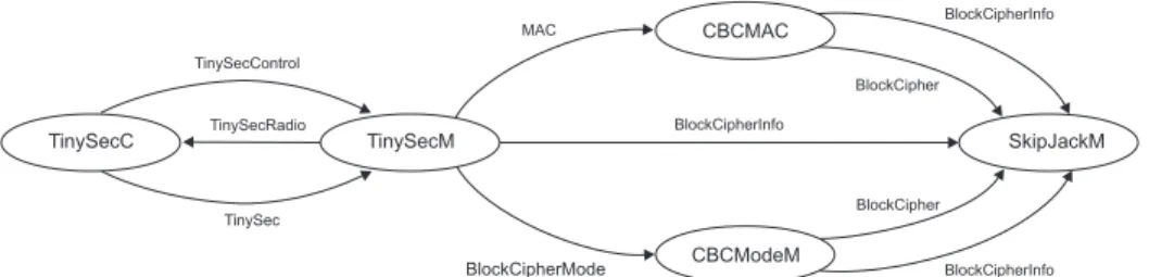
TinySecC TinySecM CBCModeM CBCMAC SkipJackM TinySecRadio TinySec TinySecControl BlockCipherInfo MAC BlockCipherMode BlockCipherInfo BlockCipher BlockCipher BlockCipherInfo
Figure 2.Relationship between components in TinySec.
2. Existing Link-Layer Security Protocols
In this section we review some of the proposed link-layer security frameworks for sensor networks. To facilitate their evaluation we first introduce some requirements based on the discussion in Section 1. Then, during the review of each protocol we will elaborate on whether and how it satisfies these requirements.
• Flexibility: Various security services should be supported but not imposed to the application level communications. This means that the run-time composition of security services (see Section 1.4) should be provided.
• Scalability: Adding or deleting nodes should have minimum overhead in terms of energy consumption and memory usage as well as having no effect on the functionality of the security scheme.
• Transparency: The provision of security services should be transparent to other components or services.
• Lightweightness: The constrained resources of sensor nodes especially limited memory and computational power should be taken into account.
• Node Capture Resistance: The effects of node capture attacks should be con-strained as much as possible. If a node is compromised it should not allow the attacker to disclose the communication in the whole network.
• Simplicity: The integration of this scheme with other services or components should have a minimal overhead.
2.1. TinySec
TinySec [18] is a link-layer security architecture for wireless sensor networks that is part of the official TinyOS release. It generates secure packets by encrypting data packets us-ing a group key shared among sensor nodes and calculatus-ing a MAC for the whole packet including the header. It provides two modes of operation for communication namely, au-thenticated encryption and authentication only. Authentication only is the default mode of operation, where the payload in the TinyOS packet is not encrypted; each packet is simply enhanced with a MAC. In the authenticated encryption mode the payload is en-crypted before the MAC is computed on the packet. The key distribution mechanism was left out and must be implemented as a separate part of the software. The TinySec architecture is shown in Figure 2.
Dest (2) AM (1) Len (1) Grp (1) Data (0...29) CRC (2) Dest (2) AM (1) Len (1) Data (0...29) MAC (4) Dest (2) AM (1) Len (1) Data (0...29) MAC (4) Src (2) Cntr (2)
(a) TinyOS packet format
(b) TinySec-Auth packet format
(c) TinySec-AE packet format
Authenticated
Encrypted Authenticated
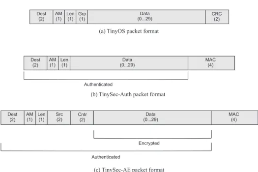
Figure 3.TinySec packet format in the TinySec-Auth and TinySec-AE modes.
2.1.1. Encryption and Authentication
TinySec uses a block cipher algorithm for its encryption scheme that is also used for the message authentication code (MAC) resulting in greater code efficiency. In particular the authors chose the Skipjack block cipher in cipher block chaining (CBC) mode for encrypting TinyOS packets. However, instead of a random IV, they used a counter, which is pre-encrypted. They also used the cipher stealing technique to ensure the ciphertext is the same length as the underlying plaintext. For the authentication of packets, TinySec uses the same block cipher encryption in CBC-MAC mode to generate a 4 byte Message Authentication Code (MAC) for each message. To provide additional security, it XORs the encryption of the message length with the first plaintext block.
2.1.2. TinySec packet format
Figure 3 shows the packet formats for the two modes of TinySec, authenticated en-cryption (TinySec-AE) and authentication only (TinySec-Auth). As observed, the header fields do not get encrypted, to allow motes quickly determine whether they should re-ject the packet. The destination address and the AM type are used by the motes for this purpose.
To detect transmission errors, TinyOS motes compute a 16-bit cycle redundancy check (CRC) over the packet. At the receiver the CRC is re-computed and verified with the CRC field in the packet. If they are equal, the receiver accepts the packet and re-jects it otherwise. However, CRCs provide no security against malicious modifications or forgery of packets. TinySec replaces the CRC and the GroupID fields with a 3-byte MAC. The MAC protects the payload as well as the header fields. So, since the MAC can detect any changes in the packet, it can also detect transmission errors, therefore CRC is no longer needed.
In the TinySec-AE mode, the data field (payload) is encrypted by the block cipher in CBC mode. Then the MAC is computed over the encrypted data and the packet header. In order to reduce overhead, TinySec uses an 8 byte IV, which is composed of all the header fields in Figure 3(c). In this case the overhead is only 4 bytes, i.e. the source address and a 16-bit counter. This raises an issue on the security level due to the repetition of the IV value. Since the counter is 16 bits, a node can send216packets before IV reuse occurs. However, when this happens, only the length (in blocks) of the longest shared prefix of the two repeated messages will be revealed, since CBC mode is used.
2.1.3. TinySec limitations
TinySec by default relies on a single key manually programmed into the sensor nodes before deployment. This network-wide shared key provides only a baseline level of se-curity. It cannot protect against node capture attacks. If an adversary compromises a sin-gle node or learns the secret key, she can gain access on the information anywhere in the network, as well as inject her own packets. This is probably the weakest point in TinySec, as node capture has been proved to be a fairly easy process [19]. As we will see in later sections, more recent link-layer security protocols have used stronger keying mechanisms to deal with node capture attacks.
Another limitation of TinySec is that messages of less than 8 bytes are not addressed efficiently. This is because TinySec uses ak-byte block cipher to encrypt the message. For longer messages CBC mode is chosen that encrypts the message block by block. But it is not so unusual for a message (i.e. the payload of the TinyOS packet) to be less than 8 bytes, in which case TinySec will cause a ciphertext expansion, because ciphertext stealing requires at least one block of ciphertext. This kind of ciphertext expansion would cause extra communication power cost when sending data with variable length.
2.2. SenSec
SenSec is a link layer security platform similar to TinySec but with a slightly different packet type and a more resilient keying mechanism. The provision of security services is transparent so that the applications running on the sensors are not aware of the operations on encryption and authentication taking place at the link layer.
While TinySec offers the option between authentication-only and authentication with encryption (AE), SenSec has only one default mode: authentication with encryp-tion. SenSec uses an 8 byte initial vector (IV) and a block cipher in cipher block chaining (CBC) mode to encrypt the data field of the packet, just like TinySec in AE mode. Their difference, however, comes from the IV format. The fixed portions of both IVs are the destination address, the AM type and the length fields. These fields take 4 bytes totally. TinySec fills the other portions of its IV with a 2 byte source address and a 2 byte counter. While this is a reasonable solution so that IV is not repeated often, it requires the nodes to maintain a counter that increases both storage and computation cost. In order to avoid the cost of using a counter mode, SenSec employs a random number mode to generate a three byte random number and fills the IV field with that number along with the one byte group ID.
Instead of generating random numbers with a new algorithm, SenSec employs the existing block cipher module that uses as the main security primitive in its architecture. For simplicity, the first random number is generated by encrypting the first packet header
Dest (2) AM (1) Len (1) Data (0...29) MAC (4) Grp (1) Ran (2) Encrypted Authenticated
Figure 4. SenSec packet format.
with 3 byte random number field set to 0. Then, the three least significant bytes of the ciphertext are used to fill the random number field in the packet. For the next packets, the 3 byte random number field is determined from the 3 least significant bytes of the MAC, which is computed and stored during the previous packet formatting.
There have been slight enhancements in the cryptographic primitives used in SenSec to improve the security of the platform and further reduce the energy consumption. While 80-bit key Skipjack block cipher is used as the encryption primitive in TinySec, SenSec uses a variant of Skipjack called Skipjack-X which is more resilient against exhaustive key search attacks. It has been shown that SkipjackX is as secure as Skipjack with re-spect to the various attacks such as the differential cryptanalysis and linear cryptanalysis. Furthermore, it proves stronger against brute force attacks which are the most practical attacks against many block ciphers with small key sizes.
The computation cost of the encryption and MAC is also reduced in SenSec. While TinySec requires two block cipher operations for each message block in a two-pass authentication-encryption scheme, SenSec uses a one-pass authentication-encryption scheme called XCBC. This scheme is secure as long as the total amount of packets being encrypted and authenticated with the same key is much less than 232. Also, similar to TinySec, SenSec uses 32 bit MACs in order to reduce the packet size.
The default XCBC mode in SenSec, carries out the encryption and authentication for every packet. The reason that SenSec designers have chosen XCBC as their default mode is that it causes the encryption to be done without additional cost, while the encryption in TinySec needs separate CBC-mode operations.
2.2.1. SenSec Packet Format
SenSec’s packet format is built upon the current TinyOS packet format and improves slightly upon the TinySec packet format. Figure 4 illustrates the packet format used in SenSec. Compared with TinySec, the unchanged fields in SenSec are the destination field, the active message type and the length field. Unlike TinySec, SenSec keeps the Group ID field, which is also contained in the original TinyOS packet format.
2.2.2. SenSec’s Keying Mechanism
In a wireless sensor network, different packets are exchanged between different entities (e.g. sensor to base station, sensor to gateway, etc.). These packets might have different security requirements. For example sensor readings forwarded to the base station need confidentiality and authentication, while routing packets need authentication only. A sin-gle keying mechanism such as TinySec’s cannot satisfy all these requirements and there-fore, designers of SenSec use a many-keying mechanism to protect the whole network from various attacks on one hand, and on the other hand to support effective sensor func-tions like in-network processing. SenSec employs three level of keys, namely global key
(GK), cluster key (CK) and sensor key (SK) to map the sensor deployment. All of the keys are generated and pre-loaded before deployment.
SenSec’s keying mechanism provides some partial resilience against node capture attacks compared to TinySec: if a sensor node is compromised, an adversary can only disclose the group communication of that node through the cluster key,CK. She can also broadcast messages to the network using the global key,GK. But still its node capture resilience is better than that provided by TinySec, which uses only one network-wide shared key.
2.3. SNEP
SNEP (Sensor Network Encryption Protocol) is a building block of SPINS [20] that provides data confidentiality, two-party data authentication, integrity, freshness, seman-tic security and replay protection. SNEP uses symmetric cryptography with one crypto-graphic function (RC5) for all of the encryption, decryption, MAC, pseudo random num-ber generation and hash function operations. In order to prevent any potential interaction between the cryptographic primitives that might introduce a weakness, SNEP derives independent keys for its encryption and MAC operations.
SNEP employs the CBC-MAC scheme to construct message authentication codes. For the underlying block cipher it uses RC5. SNEP also offers semantic security by randomization. In order to avoid the extra overhead of sending the randomized data with the packet, it introduces a shared counter between the sender and the receiver which is used as an initialization vector (IV) for the block cipher in counter mode (CTR). Since the counter state is kept at each end point it is not required to be transmitted over the radio channel. The counter value is long enough that it never repeats within the lifetime of the node. This counter value in the MAC also prevents replaying old messages as any messages with the old counter values would be discarded by the device. However, since the counter value is not being sent with the packet, there might be synchronization problems caused by dropped packets. So a re-synchronization protocol may be needed to overcome this problem.
2.4. MiniSec
MiniSec has two different operating modes for unicast and broadcast communication be-tween sensor nodes, called MiniSex-U and MiniSec-B respectively. Both schemes em-ploy the OCB-encryption scheme for both encryption and authentication. They also pro-vide semantic security by the use of a counter as a nonce. In the case of the unicast mode two synchronized counters are kept at the sender and at the receiver, while in the broad-cast mode the authors propose the use of a Bloom-filter2based mechanism that precludes per-sender state.
2.4.1. MiniSec-U
In unicast mode, MiniSec requires each pair of nodes in the network to share two keys: KABandKBAforA→BandB→Acommunication, respectively. A 32-bit counter
2A Bloom filter is a space-efficient probabilistic data structure that is used to test whether an element is a
that is increased for each new message is assigned to each key to guarantee semantic security. CounterCAB is used for keyKAB and counterCBAfor keyKBA. Only the
lastxbits of the counter value are included in each packet to save the energy of trans-mitting more bits. Both sender and receiver keep track of the counters which have to be synchronized on both sides. The receiver can accept only messages with a counter value greater than this in the previous messages. However the counters can be desynchronized and a counter resynchronization protocol is needed.
Unless it is known before deployment which pairs of nodes are going to use unicast communication, each node in the network should maintain a counter for each possible sender (i.e. its neighbors), resulting in high memory overhead and making counter resyn-chronization very expensive. These problems also dictate the use of a different mecha-nism for the broadcast case.
2.4.2. MiniSec-B
Two mechanisms are used in MiniSec-B to provide semantic security and replay protec-tion. The first one requires time synchronization among the nodes and divides time in epochsE1, E2, E3, . . .. The number of the current epoch is used as the nonce for OCB-encryption. When a node receives a packet, it attempts decryption twice; one with the current epoch number and one with the immediately previous epoch number. The epoch length is defined in a way that compensates for time synchronization errors and network latency.
The second mechanism defends against replay attacks within the current epoch. Each sender nodes keeps a counter which is incremented for each new message. At the end of each epoch the counter is reset, which means it can be shorter than the counter in MiniSec-U (the authors found that it was sufficient to use an 8-bit counter). The receiver keeps two alternating Bloom filters, one for the current epoch and one for the previous epoch. Each time it receives a packet it queries the corresponding Bloom filter and if the query returns true, the packet is considered to be a replay. The problem, however, is that the Bloom filters may cause false positives, causing a legitimate packet to be rejected as a replayed packet.
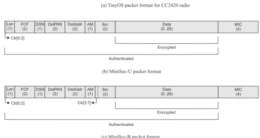
2.4.3. MiniSec packet format
Figure 5 shows the packet formats for MiniSec-U and MiniSec-B compared to the TinyOS packet format for the CC2420 radio (compliant with IEEE 802.15.4). Like in TinySec, the Group ID has been removed from the header, since access control is achieved through the use of different cryptographic keys. The 2-byte CRC is replaced by a 4-byte MIC (Message Integrity Code). The difference between MiniSec-U and MiniSec-B is that for the unicast mode, only x= 3bits of the counter are sent in the packet header, while for the broadcast mode the whole counter has to be sent.
2.5. SecureSense
SecureSense [21] provides dynamic security service composition using the TinySec in-frastructure. It introduces a new 1-byte field in its packet format called SCID as an indi-cator of the services provided by the message. The values of the bits in this field deter-mine the combination of services provided, like confidentiality, integrity, semantic secu-rity and replay protection.
Data (0..28)
(a) TinyOS packet format for CC2420 radio
Len (1) FCF (2) DSN (1) DstPAN (2) DstAddr (2) AM (1) Grp (1) CRC (2)
(b) MiniSec-U packet format
Len (1) FCF(2) DSN (1) DstPAN (2) DstAddr (2) Data (0..28) MIC (4) Src (2) Encrypted Authenticated AM (1)
(c) MiniSec-B packet format
Len (1) FCF (2) DSN (1) DstPAN (2) DstAddr (2) Data (0..28) MIC (4) Src (2) Encrypted Authenticated AM (1) Ctr[0:2] Ctr[0:2] Ctr[3:7]
Figure 5. MiniSec packet format in the unicast and broadcast modes.
SCID has replaced the TinyOS active message type (AM) field in order not to in-crease the packet length and consequently, the packet transmission time. However, the removal of active message type field introduces several major problems for upper layer services as it directly affects the Active Message Modelof TinyOS. According to this model, each packet on the network specifies a handler ID that will be invoked on re-cipient nodes. When a message is received, the receive event associated with this ID is signalled. This mechanism allows different network protocols to operate concurrently without conflict. Removing the AM ID, therefore, significantly affects implementation of such protocols under TinyOS and introduces new complexities.
2.6. ZigBee
Security services provided for ZigBee include methods for key establishment, key trans-port, frame protection, and device management[22]. To secure messages transmitted over a single hop, ZigBee uses MAC layer security, provided by the IEEE 802.15.4 standard, while for multi-hop messages it relies on higher layer security (i.e. the network layer).
The ZigBee specifications provide different means to achieve the following security requirements:
• Authentication: Network level authentication is achieved by using a common net-work key. Authentication of messages exchanged between two nodes is achieved by using unique link keys shared by these nodes. This prevents insider and out-sider attacks but requires high memory usage.
• Encryption: ZigBee uses 128-bit AES encryption. Encryption protection is pos-sible at network level or link level. As some applications may not need any en-cryption, encryption can be turned off without impacting freshness, integrity, or authentication.
• Freshness: ZigBee nodes maintain incoming and outgoing freshness counters to maintain data freshness. These counters are reset every time a new key is cre-ated. Devices that communicate once per second will not overflow their freshness counters for 136 years.
• Message Integrity: ZigBee specifications provide options of providing 0, 32, 64 or 128 bit data integrity for the transmitted messages. The default is 64 bit integrity. Encryption at the MAC layer is done using AES in Counter (CTR) mode and in-tegrity is done using AES in Cipher Block Chaining (CBC- MAC) mode [16]. A com-bination of encryption and integrity is done using a mixture of CTR and CBC- MAC modes called the CCM mode. Encryption at the network layer is also done using AES. However, in this case the security suites are all based on the CCM* mode of operation. The CCM* mode of operation is a minor modification of the CCM mode used by the MAC layer. It includes all of the capabilities of CCM and additionally offers encryption-only and integrity-encryption-only capabilities. These extra capabilities simplify the network layer security by eliminating the need for CTR and CBC-MAC modes.
3. Building Transparent Security Services
In the previous section we reviewed some of the most known link-layered security frame-works for sensor netframe-works. In the remaining sections we move to describing in more details the issues involved in designing such a framework. In particular, we are going to emphasize in the design and implementation of the following two main mechanisms necessary to achieve the various security requirements:
• Key management techniques that look into the different ways to establish and distribute cryptographic keys among the different nodes in the sensor network, and
• Mechanisms used to encrypt the important data (to provide data confidentiality) and to calculate the MAC (to provide data authenticity and data integrity) using the established cryptographic keys.
So, first we begin by describing a key management scheme that will provide the necessary keys for our security framework (called L3Sec, for Lightweight Link Layer Security, first presented in [23]), and then in Section 3.2 we complete it by showing how it provides secure services to the higher levels.
3.1. Key Management Module
In the bibliography there are three major approaches for key management in WSN: • Deterministic pre-assignment. Examples of this approach are SPINS[20] and
LEAP[24] in which unique symmetric keys shared by the nodes with the base station are assigned before the network is deployed. Using this approach, cryp-tographically strong keys can be generated, however, this involves a significant pre-deployment overhead and is not scalable.
• Random pre-distribution. Schemes like those in [25], [26] and [27] and PIKE[28] refer to probabilistically establishing pair-wise keys between neighboring nodes
in the network. Usually in this approach a random subset of keys from a key pool is pre-assigned to every node; two nodes establish a pair-wise key based on the subset of the shared keys between them. This framework is quite flexible; the choice of protocol parameters determines the trade-off between scalability and resiliency to node capture. However, most of the key pre-distribution schemes rely on sensor nodes to broadcast a large number of pre-loaded key IDs to find pair-wise keys between neighboring nodes, thus leading to a huge communication overhead. In addition, to guarantee network connectivity, each node has to store several hundreds keys or key spaces, which may greatly decrease the memory availability.
• Deterministic post-deployment derivation. In this approach, nodes use some glob-ally shared secret and pseudo-random number generators to derive the keys at run-time. LEAP[24] use this approach in order to establish pair-wise and group keys. A node erases the global secret after the completion of the initial key establish-ment phase to provide resilience against possible node compromises. However, most of the techniques based on this approach make it infeasible for even non compromised nodes to generate new keys at a future time making these protocols inefficient for dynamic sensor network topologies.
The key management scheme that we describe in this section follows the post-deployment approach with support for newly added nodes. It addresses flexibility and scalability issues and is resistant to node capture attacks. This module forms the core of the L3Sec framework described in the next section, but it can also be used as a stand alone component or it can be easily integrated into other security protocols providing the related services to them.
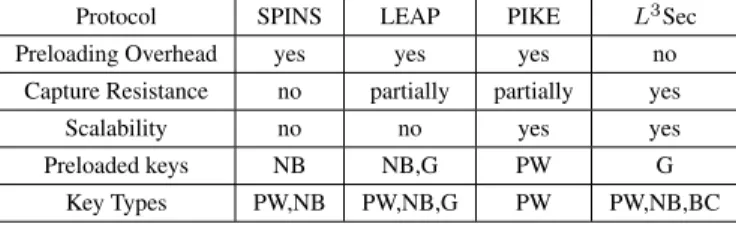
A comparison of the above-mentioned key management schemes as well as the one presented here is given in Table 1.P W stands for pair-wise keys,Gstands for a global key common among all nodes, N B is the node-base key common between each one of the nodes and the base station, andBC is the broadcast key of each node common between the node and its neighbors.
Table 1. Comparison of key establishment protocols in WSN
Protocol SPINS LEAP PIKE L3Sec
Preloading Overhead yes yes yes no
Capture Resistance no partially partially yes
Scalability no no yes yes
Preloaded keys NB NB,G PW G
Key Types PW,NB PW,NB,G PW PW,NB,BC
3.1.1. The Key Establishment Protocol
Before the sensor nodes start establishing the keys, they need to run aneighbor discovery
phase. This is achieved in two steps by a pair of handshake messages. In the first step, nodeibroadcasts a specific type of message containing its ID so that every other node ini’s communication range (likejfor example) can receive it. We refer to this message as aping message. Every node receiving the ping message answers back to the sender (i) with apong messagecontaining its ID (steps 1 and 2 in Table 2). Nodeican then
addjto its own neighbor list. After a sufficient amount of time (see Table 3 and more explanations in Section 3.1.2),iwill discover all of its neighbors and this phase will be finished.
Next, we need to provide cryptographic keys in order to secure both one-to-one and one-to-many communication in a wireless sensor network. For this purpose the protocol establishes three different kinds of keys in each sensor node:
1. Pair-wise (PW) key that is established between two neighbors to protect their one-to-one communications.
2. Broadcast (BC) keythat is established in order to secure the broadcast messages sent by a node to its neighbors.
3. Node-Base (NB) keythat is established in order to secure the communication be-tween a node and the base station (note that this communication is not necessar-ily direct). A message encrypted by this key, can only be decrypted by the base station.
Each nodeicomputes its own node-base key and its pair-wise keys with its neigh-bors as well as their broadcast keys as follows:
N Bi=F(i||baseStationAddress||K)
P Wi,j=F(min(i, j)||max(i, j)||K)
BCi=F(i||K)
where “||" is the concatenation operator andF is a secure pseudo-random function usu-ally implemented by a hash function such as SHA-1 or MD5.Kis a global master key that is distributed to all nodes before deployment of the network. As we will explain later, Kwill eventually be deleted from the memory of the nodes in order to make the scheme more secure against node capture attacks.
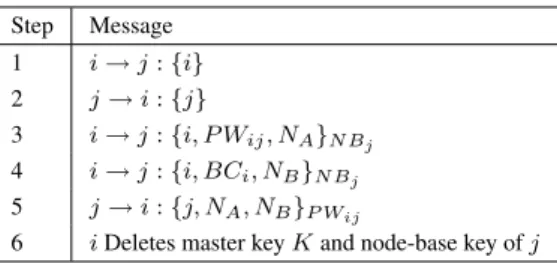
Table 2. Steps of Key Establishment Protocol
Step Message 1 i→j:{i} 2 j→i:{j} 3 i→j:{i, P Wij, NA}N Bj 4 i→j:{i, BCi, NB}N Bj 5 j→i:{j, NA, NB}P Wij
6 iDeletes master keyKand node-base key ofj
When these calculations are over, nodeihas a complete table of all the needed keys. However, it needs to announce its pair-wise and broadcast keys to its neighbors in order to communicate with them. In other words, a neighbor nodejhas to update its key table with the keys corresponding to nodei. Thus, nodeihas to send a messageMcontaining these keys to nodej. Obviously,Mshould not be sent in plain. Therefore, nodeishould calculate an appropriate key in order to send an encrypted version ofM to nodej. A proper key, as we will see, is the node-base key of nodejwhich can be derived byias follows:
N Bj=F(j||baseStationAddress||K)
Having this key, nodeican encrypt and send tojthe key it shares with it (P Wi,j)
as well as its own broadcast key (BCi). The related messages are the following (Steps 3
and 4 in Table 2):
i→j:{i, P Wi,j, NA}N Bj
i→j:{i, BCi, NB}N Bj
whereNAandNB are two nonces to guarantee the freshness of these messages3.
After sending these two messages, nodeiwill delete the node-base key of nodej from its memory. Therefore the only non-base station node that can decrypt these mes-sages is nodej (note that we assume the base station is secure). Nodeiwill also delete the master keyKfrom its memory.
Upon receiving the keys, nodej will answer back to nodeiby sending a message containing the noncesNAandNB. This message is encrypted with the pair-wise key of
iandj(Step 5 in Table 2). At this point, key establishment is complete.
Notice how this message exchange enforces thescalabilityaspect of the protocol: related keys can be established when a new node is added to a previously deployed net-work. Any new node that joins the network (such asi) can initiate the key establishment phase by broadcasting aping message. Following that, related keys are calculated by the new node. Then the broadcast key of this added node, as well as its pair-wise keys with each of its neighbors are sent to related neighbors, encrypted with their node-base keys.
Using the node-base keys for this purpose is quite an appropriate choice in order to make the protocol scalable and secure. This is because the already available network nodes have already deleted the master keyKfrom their memory and consequently can-not use it to either calculate the keys or decrypt any message encrypted with it. It is can-not a good idea to use the broadcast key of previously joined neighbor nodes (likej) since other neighbors ofjhave that key available and can decrypt messages encrypted with it; a fact that results in providing a looser security scheme.
The deletion of master key K and the temporarily calculated node-base key ofj (N Bj) byimakes the protocol resilient to node capture attacks. It reduces the negative
consequences of capturing a node as the attacker will gain access only to that neighbor-hood andnot the entire network. Since the needed time for key establishment is negligi-ble, we can assume that the adversary does not have enough time to find the master key K before it is deleted from the memory of the nodes (see also LEAP[24] for a similar assumption).
Moreover, newly joined nodes must come with the master keyK in order to cal-culate the cryptographic keys. Therefore, an adversary cannot introduce new nodes to the network, since she doesn’t knowK. In addition to that, it is important to note that if one of the above mentioned messages in key establishment protocol is not delivered, 3The reason that messageMis broken into two consecutive messages is only a practical nuance. The overall
size ofM– combination of the two mentioned messages – which would be 32 bytes (node ID is 2 bytes and the pair-wise key, the broadcast key and the nonce are 10 bytes each) is larger than the maximum allowed message size in TinyOS which is 29 bytes. Hence, we were forced to breakMinto two different messages. However, if keys are 8 bytes long then these two messages can be merged to one.
KeyEstablishmentM KeyInterface MD5M TinySecAppC GenericComm TimerC KeyInterface TinySecApp Md5 Timer SendMsg ReceiveMsg
Figure 6. Key establishment module architecture.
the receiving node will not get stuck. If nodeidoes not receive the last message of the protocol (Step 5 in Table 2), it will not add any entry for nodejin its key table.
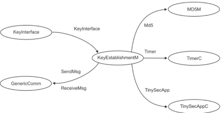
3.1.2. Implementation and Performance
We implemented the key management module described above in TinyOS in order to study its time and memory overhead and energy consumption. Figure 6 depicts the com-ponents of the key establishment module and how they are wired together.
As a stand alone library, this module implements an interfaceKeyInterfacewhich contains three commands and three events. Commandinit(k)initializes the key estab-lishment module. When all of the keys are established among current nodes, the user will be notified by aninitDone() event. Other commands provide security services such as encryption, decryption and MAC computation. The higher level application can use these services to design and implement its own security scheme. The complete solution dis-cussed in Section 3.2 provides even more transparent security services embedded in im-plemented interfaces,Send() andReceive(). The MD5 module is used as pseudo-random function that is needed to establish the different type of keys.
The memory overhead of the key management module for each node can be calcu-lated as follows:
Overhead M = [(|BC|+|P W|)∗d] +|N B|,
where|BC|,|P W|and|N B|are the size of broadcast key, pair-wise key and node-base key respectively and dstands for the maximum number of neighbors each node may have4. The default size of all types of keys in the key establishment module is 10 bytes, which provides strong security (280bit key space) for sensor network applications. As a result, in a very dense network whered= 50, we will haveM ≈1KB. Although this value ofdis far more than enough to keep the network connected, this memory overhead is well within the memory capabilities of motes (MICA2 motes have 4KB of RAM).
During the key establishment phase, prior to deletion of the master key, an adversary has a chance to find it and use it to derive all the other keys. However, this time is so 4In our current implementation of neighbor discovery phase, a node willing to discover its neighbors,
broad-casts a ping message and waits fortmilliseconds to receive pong messages from the potential neighbors. Yet it discards pong messages if they arrive aftertmilliseconds or if the number of discovered neighbors is already d. Values ofdandtare decided during deployment time and play important roles in network connectivity.
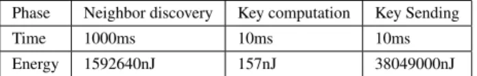
Table 3. Required time and energy before the global key deletion
Phase Neighbor discovery Key computation Key Sending
Time 1000ms 10ms 10ms
Energy 1592640nJ 157nJ 38049000nJ
small that the probability that the attacker will capture a mote and retrieve the key is con-siderably small. Table 3 shows the related duration (calculated with Tossim) that it takes to delete the master key from memory of a newly added mote during its initialization phase5.
Table 3 also presents the estimated amount of energy consumption for each phase of the key establishment for the same network (d= 50). This estimation was calculated by multiplying the total amount of communications by an average communications cost of 18µJ/bit(see PIKE[28] for a similar assumption). As a result, the estimated energy consumption of the key management scheme presented here is approximately0.4J(note that as presented in Table 3 the energy needed for key computation is quite smaller than the needed energy for communication) comparing to PIKE-2D that is more than 8J or PIKE-3D[28] which is around 6J. This high energy efficiency of theL3Sec’s key establishment scheme comes with a comparable cost in terms of memory overhead; it uses about 1000 bytes of memory to establish and manage the keys while PIKE-2D and PIKE-3D need around 600 bytes and 500 bytes respectively.
In the L3Sec’s key establishment scheme the effect of having a node captured is reduced to its neighborhood, i.e. the captured node’s pairwise keys with its neighbors, its broadcast key and its node-base key are the only keys that can be retrieved by the ad-versary. This is a small fraction of the established keys and communication still remains secure in the rest of the network.
3.2. A Link-layer Security Framework
Having built a key management scheme to use as the base, we now present theL3Sec link-layer security framework, first proposed in [23] and compare it with other similar protocols that we reviewed in Section 2. The main goal of this framework is to be trans-parent and easy to use. More specifically, it features the following properties:
• The process of key establishment as well as related computations regarding the provision of security services such as confidentiality and authentication is com-pletely hidden from the protocols in the upper layers.
• It is flexible so that the developers can adapt it to the security needs of their applications. This is an important requirement, especially in resource constrained systems such as sensor networks. As different messages being exchanged in the network require different security services, a security platform has to be flexible enough to address all the security needs of different types of communications while not imposing extra overhead due to redundancies.
Additional to these features, the security framework satisfies the properties that we described in Section 1, namely data confidentiality, data authentication, semantic security 5The higher the value oft, the higher the time prior to the deletion of master key. The current value of t= 1000msas appears in Table 3 is quite appropriate for a very dense network whered= 50and all of the nodes are supposed to be able to discover all of their potential neighbors.
and freshness. Next we describe what approaches have been taken for each of these properties.
3.2.1. Data Confidentiality
In order to protect the messages being exchanged among the nodes from eavesdropping by unauthorized parties, appropriate encryption mechanisms are provided. The default cipher that is used in the implementation of this framework for this purpose isSkipJack, however, the platform is not bound to use any specific cipher and related settings can be changed easily by the platform user (the other currently available cipher in the imple-mentation is RC5).
3.2.2. Data Authentication
Proper message authentication codes (MAC) are used to allow nodes detect any modifi-cations in received messages. The MAC generation is performed by applying a pseudo-random function (implemented by a hash function) to the concatenation of the message and the related established key. The default hash function that is used in the implementa-tion ofL3Sec is MD5. However, related settings can be easily changed to replace it with any other hash function, such as SHA-1.
Since the already established keys (e.g. pair-wise keys established among the neigh-bors) are used to generate the message authentication codes, network nodes are able to verify the authenticity of the received messages. Using this service, unauthorized nodes will not be able to send legitimate messages into the network. Thus, an access control service is also provided using generated MACs.
3.2.3. Freshness and Semantic Security
Common defences to protect a network from message replay attacks is to either times-tamp the messages using some network time synchronization protocol or include a mono-tonically increasing counter in related messages in order to be able to detect replayed old messages and reject them.
Providing time synchronization in WSN is usually quite complicated. Moreover, do-ing it in a secure manner is even more demanddo-ing and has to rely on a security platform like the one we describe here. As a result, in the implementation ofL3Sec the increasing counter approach is used to guarantee the freshness of the messages. However, the mem-ory cost of having every recipient maintaining a table of the last received counter value of all of the other nodes is quite high. This is the reason why TinySec, as pointed out by the authors of its paper, does not provide acceptable security against replay attacks.
As a matter of fact, a complete provision of such a service in link layer is not prac-tically feasible. This is because information about the network’s topology and commu-nication patterns seem to be mandatory to provide protection against replay attacks, yet this information is not available in the link layer. However, having neighbor information available at the end of the neighbor discovery phase,L3Sec lets each sensor maintain only the last counter value for itsneighborsand not for all nodes. Thus, as a message is being routed to a specific destination, the counter value is updated on each hop.
The amount of memory needed to keep the neighbors’ counter value is quite small (for example, if each counter requires 4 bytes, the total amount of memory needed to keep the counter values in avery densenetwork where each node has 20 neighbors will be 80 bytes).
Dest (2) AM (1) Len (1) Data (0...29) MAC (4) Src (2) Cntr (2) Encrypted Authenticated
Figure 7.L3Sec packet format for full security service.
3.2.4. Run-time Composition of Security Services
An approach similar to the one used in SenSec is not appropriate to be used in a general security framework for WSN, since it provides the highest possible degree of security for all of the exchanged messages. A more flexible scheme is provided inL3Sec by using the most significantthreebits of the data length field in the packet format as an indicator of the security service(s) to be used. These three bits are never used by TinyOS, as the maximum data length in TinyOS is chosen to be 29 bytes (see also TinySec for a similar approach). Consequently, the provision of this feature comes with no overhead.
Being motivated by TinySec,L3Sec provides run-time composition of security ser-viceswithoutremoving the AM ID or adding extra fields to support integration of ser-vices. Each one of the higher three bits of data field of the packet stands for a security service (from higher order bit to the lower: Replay Attack Protection, Access Control and Integrity, Confidentiality) and settinganybit means that the related service is pro-vided for that packet. Thus the desired services for different packets can be composed at runtime.
3.2.5. Protection against Node Capture Attacks
L3Sec is the first link-layer security framework providing acceptable resistance against node capture attacks. This feature minimizes the effects of compromising a node to the neighborhood of that node, keeping the rest of the network in a secure state. No assump-tion about tamper resistance is made. While tamper resistance might be an effective solu-tion for node capture attacks, it is considered noticeably expensive for the sensor nodes, which are intended to have low cost.
3.3. Packet Format
We conclude the description ofL3Sec by showing how the TinyOS packets should be modified to support the properties that we mentioned above. Figure 7 shows the fields included in the packet format in the full security mode.
TheSourcefield of the packet is used to find the appropriate established pair-wise or broadcast key needed for the security services. Note that TinySec does not use the
Sourcefield when it is set to authentication only (TinySec-Auth) mode. This is because it assumes that if the attached MAC of a received message is valid then it comes from an authorized source (note that in TinySec the MAC is derived using a specificglobal
key shared among all valid nodes, a bad security practice as we explained in Section 1). However, this assumption is not necessary inL3Sec, which uses established keys in order to resist against node capture attacks. As a result, we must include theSourcefield in the packet format.
Table 4. Operational modes and related settings.
Mode SetBits Omitted Fields Omitted Operations
“RAC” 111 -
-“RA” 110 - Encryption
“RC” 101 MAC MAC
“R” 100 MAC MAC & Encryption
“AC” 011 - Counter Saving
“A” 010 Counter Counter Saving& Encryption
“C” 001 MAC Counter Saving & MAC
“-” 000 All Security Fields All Security Operations
In other related service modes, such as replay attack protection mode, the packet format contains a counter (Counter). Together with the Sourcefield, this 2 bytes long counter can be used to avoid IV reuse inCBC encryption mode. InL3Sec, similar to TinySec, theIVincludes the destination address, the active message (AM) type, the data length, the source address and the counter. TheSource||Counterformat guarantees that each node can send216messages with the same AM type and the same destination, but with different IV values. As mentioned, another application of the counter value is its role in providing resistance against replay attacks.
Finally, the most significantthreebits of the data length field indicate the different major security modes that are provided. These include
1. Authentication, Access Control and Integrity (A). In this mode theCounterfield is not required, but obviously theMACfield is needed.
2. Confidentiality (C). In this mode theSourceandCounter fields are used in the packet format, however receiver nodes do not save the related counter values. 3. Replay Attack Protection (R). SourceandCounterfields are also necessary in
this mode, but the counter value of each neighbor is kept.
As we mentioned earlier, these modes can be combined in any variation setting the corresponding bits. Table 4 shows in more detail the different modes, provided services and the corresponding bit values.
Conclusion
Reviewing the proposed link-layer security frameworks for sensor networks we saw that all of them succeed in providing data confidentiality, data authentication and semantic security following some common approaches. However, what is missing is the provision of some features that would make them more secure and practical to use. These features include the resilience to node capture attack and scalability, both of which require that the framework is tied to an appropriate key management protocol. Another important feature is flexibility, which allows different types of security services for different types of communications among nodes. We presented a security framework, namelyL3Sec, which incorporates these features while at the same time it remains energy efficient and easy to use. Looking into this framework we described how the underlying key manage-ment scheme should be used and how the TinyOS packet structure should be changed for such a scheme to provide a complete range of security services and satisfy the afore-mentioned requirements.
References
[1] T. Li, “Security map of sensor network,” Infocomm Security Department, Institute for Infocomm Re-search, Tech. Rep., 2005.
[2] S. Camtepe and B. Yener, “Key distribution mechanisms for wireless sensor networks: a survey,” Rens-selaer Polytechnic Institute, Troy, New York, Technical Report 05-07, March 2005.
[3] E. Shi and A. Perrig, “Designing secure sensor networks,”IEEE Wireless Communications, vol. 11, no. 6, pp. 38–43, December 2004.
[4] L. Lazos and R. Poovendran, “SeRLoc: Robust localization for wireless sensor networks,”ACM Trans-actions on Sensor Networks, vol. 1, no. 1, pp. 73–100, 2005.
[5] T. Dimitriou and I. Krontiris,Security in Sensor Networks. CRC Press, 2006, ch. Secure In-network Processing in Sensor Networks, pp. 275–290.
[6] S. Ganeriwal, S. Capkun, C.-C. Han, and M. Srivastava, “Secure time synchronization service for sensor networks,” inProceedings of the 4th ACM workshop on Wireless security (WiSe ’05), 2005, pp. 97–106. [7] T. Ylonen, “SSH - secure login connections over the internet,” vol. Proceedings of the 6th Security
Symposium) (USENIX Association: Berkeley, CA), p. 37, 1996. [8] “OpenSSL,” Tech. Rep., 2001, available from http://www.openssl.org.
[9] S. Kent and R. Atkinson, “Security architecture for the internet protocol,” Internet Eng. Task Force RFC 2401, November 1998.
[10] V. Gupta, M. Millard, S. Fung, Y. Zhu, N. Gura, H. Eberle, and S. C. Shantz, “Sizzle: A standards-based end-to-end security architecture for the embedded internet,” inPERCOM ’05: Proceedings of the Third IEEE International Conference on Pervasive Computing and Communications, 2005, pp. 247–256. [11] J. Hill, R. Szewczyk, A. Woo, S. Hollar, D. Culler, and K. Pister, “System architecture directions for
networked sensors,” inProceedings of ASPLOS-IX, 2000, pp. 93–104.
[12] A. S. Wander, N. Gura, H. Eberle, V. Gupta, and S. C. Shantz, “Energy analysis of public-key cryp-tography for wireless sensor networks,” inPERCOM ’05: Proceedings of the Third IEEE International Conference on Pervasive Computing and Communications, 2005, pp. 324–328.
[13] E.-O. Blaß and M. Zitterbart, “Towards acceptable public-key encryption in sensor networks.” inACM 2nd International Workshop on Ubiquitous Computing, May 2005, pp. 88–93.
[14] K. Piotrowski, P. Langendoerfer, and S. Peter, “How public key cryptography influences wireless sensor node lifetime,” inSASN ’06: Proceedings of the fourth ACM workshop on Security of ad hoc and sensor networks, 2006, pp. 169–176.
[15] L. Batina, N. Mentens, K. Sakiyama, B. Preneel, and I. Verbauwhede, “Low-cost elliptic curve cryp-tography for wireless sensor networks,” inESAS 2006: Proceeding of the Third European Workshop on Security and Privacy in Ad hoc and Sensor Networks, Hamburg, Germany, September 2006, pp. 6–17. [16] P. Ganesan, R. Venugopalan, P. Peddabachagari, A. Dean, F. Mueller, and M. Sichitiu, “Analyzing and
modeling encryption overhead for sensor network nodes,” inWSNA ’03: Proceedings of the 2nd ACM international conference on Wireless sensor networks and applications, 2003, pp. 151–159.
[17] M. Bellare, J. Kilian, and P. Rogaway, “The security of the cipher block chaining message authentication code,”Journal of Computer and System Sciences, vol. 61, no. 3, pp. 362–399, 2000.
[18] C. Karlof, N. Sastry, and D. Wagner, “TinySec: A link layer security architecture for wireless sensor net-works,” inSecond ACM Conference on Embedded Networked Sensor Systems (SenSys 2004), November 2004, pp. 162–175.
[19] C. Hartung, J. Balasalle, and R. Han, “Node compromise in sensor networks: The need for secure sys-tems,” Department of Computer Science, University of Colorado, Technical Report CU-CS-990-05, Jan-uary 2005.
[20] A. Perrig, R. Szewczyk, J. D. Tygar, V. Wen, and D. Culler, “SPINS: security protocols for sensor networks,”Wireless Networks, vol. 8, no. 5, pp. 521–534, 2002.
[21] Q. Xue and A. Ganz, “Runtime security composition for sensor networks (SecureSense),” inIEEE Ve-hicular Technology Conference (VTC Fall 2003), October 2003.
[22] Z. Alliance, “Zigbee specification,” Document 053474r13, December 2006.
[23] H. Soroush, M. Salajegheh, and T. Dimitriou, “Providing transparent security services to sensor net-works,” inICC’07: Proceedings of the IEEE International Conference on Communications, Glasgow, Scotland, June 2007.
[24] S. Zhu, S. Setia, and S. Jajodia, “Leap: efficient security mechanisms for large-scale distributed sensor networks,” inCCS ’03: Proceedings of the 10th ACM conference on Computer and communications security, 2003, pp. 62–72.
[25] L. Eschenauer and V. D. Gligor, “A key-management scheme for distributed sensor networks,” inCCS ’02: Proceedings of the 9th ACM conference on Computer and communications security, 2002, pp. 41–47.
[26] H. Chan, A. Perrig, and D. Song, “Random key predistribution schemes for sensor networks,” inSP ’03: Proceedings of the 2003 IEEE Symposium on Security and Privacy, 2003, p. 197.
[27] D. Liu and P. Ning, “Establishing pairwise keys in distributed sensor networks,” inCCS ’03: Proceedings of the 10th ACM conference on Computer and communications security, 2003, pp. 52–61.
[28] H. Chan and A. Perrig, “PIKE: Peer intermediaries for key establishment in sensor networks,” in Pro-ceeding of the 24th Conference of the IEEE Communications Society (Infocom), 2005.