Digidesign
2001 Junipero Serra Boulevard Daly City, CA 94014-3886 USA tel: 650·731·6300 fax: 650·731·6399 Technical Support (USA) tel: 650·731·6100 fax: 650·731·6384 Product Information (USA) tel: 650·731·6102 tel: 800·333·2137 International Offices Visit the Digidesign Web site for contact information Web Site www.digidesign.comSYNC I/O Guide
Version 1.0
For Pro Tools 5.3.1
Copyright
This guide is copyrighted ©2002 by Digidesign, a division of Avid Technology, Inc. (hereafter “Digidesign”), with all rights reserved. Under copyright laws, this guide may not be duplicated in whole or in part without the written consent of Digidesign.
DIGIDESIGN, AVID and PRO TOOLS are trademarks or registered trademarks of Digidesign and/or Avid Technology, Inc. All other trademarks are the property of their respective owners.
All features and specifications subject to change without notice.
PN 910609328-00 REV B 06/02
Communications & Safety Regulation Information Compliance Statement
The model SYNC I/O complies with the following standards regulating interference and EMC:
• FCC Part 15 Class A • EN55103 – 1, environment E4 • EN55103 – 2, environment E4 • AS/NZS 3548 Class A • CISPR 22 Class A
Radio and Television Interference
This equipment has been tested and found to comply with the limits for a Class A digital device, pursuant to Part 15 of the FCC Rules.
Communications Statement
This equipment has been tested to comply with the limits for a Class A digital device. Changes or modifications to this product not authorized by Digidesign, Inc., could void the Certification and negate your authority to operate the product. This product was tested for CISPR compliance under conditions that included the use of peripheral devices and shielded cables and connectors between system components. Digidesign recommends the use of shielded cables and connectors between system components to reduce the possibility of causing interference to radios, television sets, and other electronic devices.
Safety Statement
This equipment has been tested to comply with USA and Canadian safety certification in accordance with the specifications of UL Standards; UL6500 and Canadian CSA standard; CSA C22.2 No.1-M90. Digidesign Inc., has been authorized to apply the appropriate UL & CUL mark on its compliant equipment.
Important Safety Instructions
When using electric or electronic equipment, basic precautions should always be followed, including the following:
• Read all instructions before using this equipment. • To avoid the risk of shock, keep this equipment away from
rain water, and other moisture. Do not use this equipment if it is wet.
• The equipment should only be connected to the correct rating power supply as indicated on the product. • Do not attempt to service the equipment. There are no
user-serviceable parts inside. Please refer all servicing to authorized Digidesign personnel.
• Any attempt to service the equipment will expose you to a risk of electric shock, and will void the manufacturer’s warranty.
• The product should be connected only to the correct power supply as indicated on the product.
Contents iii
contents
Chapter 1. Introduction
. . . 1System Requirements. . . 2
SYNC I/O Features . . . 4
Compatibility Information. . . 4
About This Guide. . . 5
Chapter 2. Installation and Getting Started
. . . 7Hardware Connections . . . 7
9-Pin for MachineControl. . . 11
Synchronization and Time Code Connections to Machines, Decks, and Other Devices . . . 12
Software Installation. . . 14
Getting Started with Pro Tools|HD and SYNC I/O. . . 14
MachineControl Configuration. . . 18
Software Configuration for SYNC I/O Setup Software . . . 19
Getting Started with Pro Tools|24 MIX and Pro Tools|24 . . . 19
Updating SYNC I/O Firmware . . . 20
Troubleshooting . . . 21
Chapter 3. SYNC I/O Hardware and Software Overview
. . . 23SYNC I/O Front Panel . . . 23
SYNC I/O Back Panel . . . 26
Chapter 4. Using Sync I/O
. . . 31SYNC I/O Controls in Pro Tools, SYNC I/O Setup and the Front Panel . . . 32
Using the Front Panel Generator/Parameter Switches . . . 33
Clock References and Options. . . 35
Positional Reference and Options . . . 41
Generating & Regenerating Time Code. . . 45
Generating a Window Burn . . . 51
Chapter 5. Additional Operational Information
. . . 55Front Panel Generator/Parameter Controls. . . 55
Using Fader Start. . . 60
Calibrating the SYNC I/O Oscillator. . . 61
Restoring Factory Settings. . . 62
Managing and Selecting Video Inputs. . . 63
Appendix A. Additional Synchronization Information
. . . 65Video and VITC Signals. . . 65
LTC Signals . . . 66
Auto-Switch LTC/VITC. . . 66
Digital Clock Signal Types. . . 67
Bi-Phase/Tach. . . 68
Pilot Tone . . . 69
Contents v
Appendix C. Wiring Diagrams Pin Assignments
. . . 79LTC . . . 79
BiPhase/GPI/Pilot. . . 80
Bi-phase/Tach OptoCoupler Input. . . 81
GPI Relay Outputs. . . 82
GPI (TTL)/MTC Outputs . . . 83
GPI (opto) Inputs. . . 84
Connector Pin Assignments . . . 85
SYNC I/O Serial Cable Pin Assignments. . . 87
Bi-phase/Tach/GPI/Pilot Port Interfacing Notes. . . 87
Chapter 1: Introduction 1
chapter 1
Introduction
Welcome to the Digidesign SYNC I/O, a multi-purpose synchronization peripheral for Pro Tools|HD™ systems. The SYNC I/O supports all Pro Tools|HD sample rates, and synchronizes to all major time code and clock reference stan-dards used in audio, video, film, and multime-dia production.
SYNC I/O is designed especially for
Pro Tools|HD systems, but it can also be utilized as a stand-alone synchronization device. When used with Pro Tools, most SYNC I/O features can be controlled from within the Pro Tools ap-plication. In addition, a utility application (SYNC I/O Setup™) is provided which gives software access to all SYNC I/O parameters re-motely, with or without Pro Tools. Even with-out a computer, SYNC I/O can be configured manually using its front panel switches and dis-plays.
SYNC I/O with Pro Tools
With Pro Tools|HD, SYNC I/O provides highly accurate lock to time code through the DigiSer-ial Port connection to the HD Core card. Most SYNC I/O settings are available directly from within Pro Tools.
When the SYNC I/O is used with
Pro Tools|24 MIX or Pro Tools|24, it supports all features of (and emulates on-screen) the Digide-sign USD (Universal Slave Driver).
Stand-alone Mode
SYNC I/O can be used as a stand-alone synchro-nization converter, time code generator, clock generator and time code character generator. Throughout this guide, the term “stand-alone”
refers to systems utilizing SYNC I/O but not
us-ing Pro Tools. SYNC I/O is connected to time code and clock signals as needed, and config-ured from the front panel. Optionally,
SYNC I/O Setup software can be run from a sup-ported Macintosh or Windows computer for software remote control of all SYNC I/O param-eters.
SYNC I/O Setup Software
The SYNC I/O Setup software is a remote con-trol application for SYNC I/O. SYNC I/O Setup can be used with or without Pro Tools on any supported Macintosh or Windows computer. A Macintosh serial port is required.
SYNC I/O Setup is not supported through the DigiSerial port. SYNC I/O Setup can also be in-stalled and run from a Windows computer with the appropriate cable (see “SYNC I/O Setup” on page 2 for more information).
System Requirements
Pro Tools|HD
Macintosh• A Digidesign-qualified Power Macintosh com-puter
• A Pro Tools|HD system
• Pro Tools software version 5.3.1
Windows
• A Digidesign-qualified Windows computer • A Pro Tools|HD system
• Pro Tools software version 5.3.1
Pro Tools|24 MIX and Pro Tools|24
The SYNC I/O can be used with
Pro Tools|24 MIX and Pro Tools|24 systems. When used with these systems, the SYNC I/O emulates the Digidesign Universal Slave Driver (USD). Only features supported by Pro Tools|24 MIX, Pro Tools|24, and the USD will be avail-able.
Macintosh
• A Digidesign-qualified Power Macintosh com-puter
• A Pro Tools|24 MIX, or Pro Tools|24 system • Pro Tools software version 5.1.3 or later
Windows
• A Digidesign-qualified Windows computer • A Pro Tools|24 MIX, or Pro Tools|24 system • Pro Tools software version 5.3.1
SYNC I/O Setup
(Macintosh and Windows)The optional SYNC I/O Setup application re-quires a serial connection from SYNC I/O to your computer. SYNC I/O Setup is not available through the DigiSerial port.
SYNC I/O Setup provides stand-alone software control of SYNC I/O, and firmware updating ca-pabilities. SYNC I/O Setup can be used with or without Pro Tools for complete control of all SYNC I/O features.
Macintosh
• A Power Macintosh computer running Macin-tosh OS 9 or later (OS X is not supported at this time)
• At least 2 MB of available RAM
• Virtual Memory must be turned off in the Macintosh Memory Control Panel
• An available serial (modem or printer) port, or equivalent USB converter. See “Serial Port Re-quirements” on page 3 for details.
Windows
• A Pentium-I, 90 MHz computer, running ei-ther Windows 98SE, Windows Me, Windows NT4, or Windows 2000
• An available COM port. See “Serial Port Re-quirements” on page 3 for details.
• A custom Serial-to-COM cable. See “SYNC I/O Serial Cable Pin Assignments” on page 87 for wiring information.
Chapter 1: Introduction 3
Serial Port Requirements
Pro Tools|HD Systems◆ SYNC I/O requires a Host Serial port on the
system’s HD Core card.
Pro Tools|24 MIX and Pro Tools|24 Systems
◆SYNC I/O requires a DigiSerial Port on the
sys-tem’s MIX Core or d24 “Core” card. (If using an expanded Pro Tools|24 system that includes a MIX Farm card, use the DigiSerial Port on the MIX Farm card.)
SYNC I/O Stand-alone, without Pro Tools
If you are not using Pro Tools, but are using SYNC I/O in stand-alone mode, you can use the front panel controls, or SYNC I/O Setup. SYNC I/O Setup provides total control of all SYNC I/O parameters.
Not all parameters and options can be config-ured using the front panel only. The following SYNC I/O parameters are available only through SYNC I/O Setup, or Pro Tools:
◆Variable Speed Override (VSO)
◆ Window burn parameters. While you can turn
the Window burn on or off from the front panel, you cannot configure its display parame-ters without Pro Tools or SYNC I/O Setup.
Serial Port Requirements for Using the SYNC I/O Setup Application
(Macintosh and Windows)
In order to use SYNC I/O Setup, you must have the following:
Macintosh A serial port (modem or printer, or equivalent serial port adaptor) is required for the SYNC I/O Setup application on Macintosh. Since Power Macintosh G3 and G4 computers do not contain a conventional serial port, where connection to a conventional Macintosh serial port (modem or printer port) is called for in this guide, you will need to utilize one of the follow-ing adaptors:
• Stealth Serial Port, made by GeeThree.com. • gPort Serial Adaptor, made by Griffin
Technol-ogy.
• USB Twin Serial Adaptor, model USA-28x, made by Keyspan.
Windows A COM port connection is required for the SYNC I/O Setup application on Windows. SYNC I/O Setup does not work if SYNC I/O is connected to a DigiSerial port.
SYNC I/O Cables
SYNC I/O Serial Cable A Host Serial cable is in-cluded to connect SYNC I/O to a the DigiSerial Port on a Pro Tools|HD Core, MIX Core, or d24 card, or MIX Farm when one is present in an ex-panded Pro Tools|24 system. This cable is a stan-dard Macintosh serial cable.
Windows SYNC I/O Setup on Windows requires a non-standard 8-pin to 9-pin cable to connect SYNC I/O to a COM port on any supported Win-dows computer. Wiring instructions for making the required cable can be found in Appendix C, “Wiring Diagrams Pin Assignments.”
See “SYNC I/O Controls in Pro Tools, SYNC I/O Setup and the Front Panel” on page 32 for more information.
SYNC I/O Features
SYNC I/O supports all Pro Tools|HD sample rates, including 88.2, 96, 176.4, and 192 kHz. SYNC I/O provides the following synchroniza-tion features.
Supported Positional Reference Sources
• LTC • VITC • Bi-phase/Tach
• Internal Time Code Generator • Serial Time Code
Supported Clock Reference Sources
• Loop Sync • Reference Video • Composite Video Input • Word Clock • AES/EBU Null • Pilot Tone • Internal Crystal • Bi-phase/Tach • LTC
Output and Generation
• Digidesign Super Clock (256x sample clock) • Word Clock (1x sample clock)
• AES/EBU null clock (AES “digital black”) • VITC (if a video input is present) • LTC
• MIDI Time Code (MTC)
• Two 9-pin Sony P-2 machine protocol ports, for MachineControl™-enabled systems.
Other Features
• Front panel controls and a large LED display of time code and parameters
• Integrated control of SYNC I/O from Pro Tools
• Time Code Character Generator • Remote 9-Pin Deck Emulation mode
• Fader start, provided through GPI output, for remote transport control from select Pro Tools fader movement.
• SYNC I/O Setup software for Macintosh and Windows
• SYNC I/O firmware that can be updated at any time for future upgrades
Compatibility Information
Digidesign can only assure compatibility and provide support for devices it has tested and ap-proved.
For a list of qualified computers, diskette drives, SCSI accelerators, serial port convertors, and hard drives, refer to the latest Digidesign com-patibility documents, available from Digidesign by fax or on the Digidesign Web site.
For a list of Digidesign’s contact informa-tion, see the title page of this guide.
Chapter 1: Introduction 5
About This Guide
This guide assumes you understand the basics of synchronization and time code, know how to operate devices that send or receive time code such as a video tape recorder, and how to con-nect your studio. Refer to the documentation for your studio hardware if necessary. In addi-tion, you should have an understanding of the time code requirements for your particular project.
Conventions Used in This Guide
Digidesign guides use the following conven-tions to indicate menu choices and key com-mands:
The following symbols are used to highlight im-portant information:
Convention Action
File > Save Session Choose Save Session from the File menu Control+N Hold down the Control
key and press the N key Option-click Hold down the Option key and click the mouse but-ton
Right-click (Windows) Click with the right mouse button
User Tips are helpful hints for getting the most from your system.
Important Notices include information that could affect your data or the performance of your system.
Cross References point to related sections in other Digidesign guides.
Chapter 2: Installation and Getting Started 7
chapter 2
Installation and Getting Started
SYNC I/O installation includes the following steps:
Hardware Connecting power, serial, clock, and time code to and from SYNC I/O, Pro Tools, and your other studio equipment.
Software Checking Pro Tools software, and in-stalling SYNC I/O Setup software.
For standalone SYNC I/O systems, hardware in-stallation instructions begin with “Hardware Connections” on page 7. Optional software in-stallation instructions for remote control through the SYNC I/O Setup software can be found in “Software Installation” on page 14.
Once installed, Pro Tools needs to be configured for SYNC I/O. For instructions on how to set up Pro Tools for SYNC I/O, see “Getting Started with Pro Tools|HD and SYNC I/O” on page 14.
Hardware Connections
The following are the primary hardware connec-tions required for SYNC I/O:
• AC Power
• Host Serial, to Pro Tools or computer • Clock to Pro Tools audio interfaces
• 9-pin, to external machines (requires Machi-neControl™)
• Synchronization, including positional and clock references to and from machines, decks, and other devices
Pro Tools installations require all types of con-nections. Stand-alone operation requires power and synchronization connections, with serial connection optional (for remote control using SYNC I/O Setup software).
Make sure Pro Tools is already installed and operating correctly before installing the SYNC I/O.
AC Power
The SYNC I/O AC connector accepts an IEC Standard AC Power Cable. SYNC I/O is auto power-selecting (100V to 240V) and will auto-matically work with a standard modular cable to connect to AC power receptacles in any country.
To connect AC power to SYNC I/O:
■ Plug one end of a power cable into the
SYNC I/O AC connector, and plug the other end into a wall outlet or other power source.
Serial Connections
Pro Tools systems require a serial connection be-tween SYNC I/O and the Pro Tools|HD Core card. Stand-alone setups (or any installation uti-lizing SYNC I/O Setup software) require a serial connection between SYNC I/O and a standard serial port on the host CPU (modem or printer port on Macintosh, or a COM port on Windows computers).
About the SYNC I/O Serial Cable
Host Serial SYNC I/O includes a 4 meter (ap-proximately 12 foot) standard Macintosh serial cable, to connect SYNC I/O to a DigiSerial Port on a Pro Tools|HD Core card.
For SYNC I/O Setup software on Macintosh, use the same standard serial cable.
For SYNC I/O Setup on Windows systems, a cus-tom 8-pin to 9-pin cable is required to connect SYNC I/O to a Windows COM port.
MachineControl and SYNC I/O
SYNC I/O provides two 9-pin pass-through ports which are designed for use with Digide-sign’s MachineControl software. If you use Ma-chineControl with your Pro Tools|HD system, see “9-Pin for MachineControl” on page 11 for important instructions.
Serial to Pro Tools
To connect SYNC I/O to a Pro Tools|HD system:
1 Make sure power is off on all equipment.
2 Connect one end of the Host Serial cable to
the SYNC I/O Host Serial port.
3 Connect the other end to the DigiSerial port
on your HD Core card. Do not use any other DigiSerial ports on other HD-series cards.
To connect SYNC I/O to a Pro Tools|24 MIX or Pro Tools|24 system:
1 Make sure all your equipment is powered off
(including your computer, SYNC I/O, and all Pro Tools hardware).
2 Connect one end of the DigiSerial cable to the
SYNC I/O Host Serial port (whether using a Mac-intosh or a Windows computer).
If you choose to use a longer serial cable be-tween Pro Tools and SYNC I/O, be sure it supports hardware handshaking. Wiring di-agrams can be found in Appendix C, “Wir-ing Diagrams Pin Assignments.”
Host Serial connection, SYNC I/O to Pro Tools|HD
MTC OUT HOST SERIAL
AC 100-240V, 50-60HZ, .5A 30W VIDEO REF 9-PIN OUT 2
9-PIN OUT 1 WORD CLOCK (1x,256x) VIDEO LT C I N AE S I N AE S O UT LT C O UT IN OUT IN OUT IN OUT LOOP SYNC INTERNALLY TERMINATED BI-PHASE / TACH / GPI / PILOT
SERIAL NUMBER 964530300294856
Host Serial
SYNC I/O
DigiSerial Port on Pro Tools|HD Core
Chapter 2: Installation and Getting Started 9
3 Connect the other end of the cable to the
DigiSerial Port on your MIX Core or d24 card. (If using an expanded Pro Tools|24 system that in-cludes a MIX Farm card, use the DigiSerial Port
on the MIX Farm card. See your Expanded
Sys-tems Guide for more information.)
4 Connect the rest of your equipment to
SYNC I/O as described in “Synchronization and Time Code Connections to Machines, Decks, and Other Devices” on page 12.
Serial Connections for SYNC I/O Setup
SYNC I/O Setup requires a serial connection from SYNC I/O to a Macintosh or Windows computer. (For compatibility information, see “System Requirements” on page 2.)
To connect SYNC I/O to a Macintosh computer for SYNC I/O Setup without Pro Tools:
1 Make sure the power is switched off for both
SYNC I/O and the computer.
2 Connect the SYNC I/O Host Serial port to the
modem or printer port, or serial port adaptor, of your computer.
3 Restore power to SYNC I/O, and restart your
computer.
4 Connect the rest of your equipment to
SYNC I/O as described in “Synchronization and Time Code Connections to Machines, Decks, and Other Devices” on page 12.
To connect SYNC I/O to a Windows computer for SYNC I/O Setup without Pro Tools:
1 Purchase or make the required 9-pin to 8-pin
cable. For wiring details, see “SYNC I/O Serial Cable Pin Assignments” on page 87.
2 Make sure all equipment is powered off.
3 Connect the SYNC I/O Host Serial port to an
available COM port on your computer.
4 Restore power to SYNC I/O, and restart your
computer.
5 Connect the rest of your equipment to
SYNC I/O as described in “Synchronization and Time Code Connections to Machines, Decks, and Other Devices” on page 12.
Connecting SYNC I/O to a DigiSerial Port
MTC OUT HOST SERIAL
AC 100-240V, 50-60HZ, .5A 30W VIDEO REF 9-PIN OUT 2
9-PIN OUT 1 WORD CLOCK (1x,256x) VIDEO L T C I N A E S I N A E S O U T L T C O U T IN OUT IN OUT IN OUT LOOP SYNC INTERNALLY TERMINATED BI-PHASE / TACH / GPI / PILOT
SERIAL NUMBER 964530300294856 Host Serial to (Pro Tools Audio Interface cables) DigiSerial Port of SYNC I/O CPU MIX Core, or d24
SYNC I/O Setup will not control SYNC I/O through the Host Serial port.
Clock for
Pro Tools Audio Interfaces
SYNC I/O must be connected to Pro Tools audio interfaces in the Loop Sync chain.
Connecting Loop Sync for Pro Tools|HD
(Pro Tools|HD Macintosh OnlySYNC I/O now supports Loop Sync, and can serve as Loop Sync Master. Loop Sync is a dedi-cated clock loop for synchronizing multiple HD-series interfaces. Loop Sync should only be used to connect multiple HD-series peripherals. The following steps explain how to make Loop Sync connections between the SYNC I/O and Pro Tools|HD interfaces.
To connect SYNC I/O to Pro Tools|HD interface:
1 Connect the Loop Sync Out of the SYNC I/O
to the Loop Sync In of your primary HD-series audio interface.
2 Connect the SYNC I/O Loop Sync In to the
Loop Sync Out of your HD-series interface.
When using more than one HD-series audio in-terface, make SYNC I/O the first and last unit in the Loop Sync chain.
Using Legacy Audio Interfaces
To connect SYNC I/O to a Pro Tools|HD system that also has an 888|24, 882|20, 1622, or ADAT Bridge audio interface:
1 Connect SYNC I/O Loop Sync as described in
the previous steps.
2 Connect a BNC cable from the Ext Clock Out
of your primary HD-series interface to the Slave Clock In of your first legacy audio interface.
3 If using multiple legacy interfaces, daisy-chain
their Slave Clock connections from the first in-terface Slave Clock Out to the next inin-terface Slave Clock In, and so on.
Loop Sync connections between SYNC I/O and a 96 I/O
MTC OUT HOST SERIAL
AC 100-240V, 50-60HZ, .5A 30W
VIDEO REF 9-PIN OUT 2
9-PIN OUT 1 WORD CLOCK (1x,256x) VIDEO L T C I N A E S I N A E S O U T L T C O U T IN OUT IN OUT IN OUT LOOP SYNC INTERNALLY TERMINATED
BI-PHASE / TACH / GPI / PILOT SERIAL NUMBER 964530300294856
Loop Sync SYNC I/O
Pro Tools 96 I/O
Loop Sync in an expanded Pro Tools|HD system
Clock for SYNC I/O, a 96 I/O, and an 888|24 I/O
See the Getting Started with HD Guide for external clock configuration instructions.
MTC OUT HOST SERIAL
AC 100-240V, 50-60HZ, .5A 30W VIDEO REF 9-PIN OUT 2
9-PIN OUT 1 WORD CLOCK (1x,256x) VIDEO L T C I N A E S I N A E S O U T L T C O U T IN OUT IN OUT IN OUT LOOP SYNC INTERNALLY TERMINATED BI-PHASE / TACH / GPI / PILOT
SERIAL NUMBER 964530300294856
Computer 1
ANALOG OUTPUT ANALOG INPUT AES/EBU OUTPUT AES/EBU INPUT Computer 2 8 CH Mode 2 x 4 CH Mode S/PDIF IN S/PDIF OUT SLAVE CLOCK IN SLAVE CLOCK OUT 7 8 5 6 3 4 1 2 7 8 5 6 3 4 1 2 5/6 7/8 1/2 3/4 5/6 7/8 1/2 3/4 MTC OUT HOST SERIAL AC 100-240V, 50-60HZ, .5A 30W VIDEO REF 9-PIN OUT 2
9-PIN OUT 1 WORD CLOCK (1x,256x) VIDEO L T C I N A E S I N A E S O U T L T C O U T IN OUT IN OUT IN OUT LOOP SYNC INTERNALLY TERMINATED BI-PHASE / TACH / GPI / PILOT
SERIAL NUMBER 964530300294856
Chapter 2: Installation and Getting Started 11
Connecting Slave Clock for
Pro Tools|24 MIX and Pro Tools|24
To connect SYNC I/O to a Pro Tools|24 MIX-series or Pro Tools|24-series audio interface:
■ Using a BNC cable, connect the SYNC I/O
Word Clock Out to the Slave Clock In of your primary audio interface.
When Pro Tools launches, the SYNC I/O Word Clock Out port will switch to 256x Slave Clock output. In stand-alone use, you can manually configure the SYNC I/O for 256x Base clock out-put using the front panel controls, or using
SYNC I/O Setup software. See the SYNC I/O
Guide for instructions.
About the DigiSerial Port
Pro Tools MIX and d24 cards feature a DigiSerial Port. Though this port is identical in appearance to the serial ports on your CPU, it is designed to only be used for:
• the SYNC I/O Host Serial connection • a USD Macintosh Serial connection
• a serial to 9-pin cable in combination with the MachineControl™ option for Pro Tools
Selecting a DigiSerial Port for SYNC I/O in Expanded Systems
Always connect the SYNC I/O serial cable to the DigiSerial Port on the card connected to the pri-mary Pro Tools audio interface (your MIX Core, “Core” d24, or MIX Farm if using an expanded Pro Tools|24 system).
9-Pin for MachineControl
SYNC I/O provides two 9-pin machine ports, to support direct 9-pin connection for Machine-Control-enabled Pro Tools systems. Both ports can be connected simultaneously. In this con-figuration, MachineControl and SYNC I/O pro-vide all connections required for Serial modes, remote track arming, and other
MachineCon-trol features. See the MachineControl Guide for
more information on all of its Pro Tools fea-tures.
To connect one or two machines for MachineControl Serial Control mode:
■ Connect a 9-pin cable from either SYNC I/O
9-pin Out port to the 9-pin out of the machine. You can connect two machines, one to each port, and control either one of them at any time.
Remote 9-pin Deck Emulation Mode
In order to use MachineControl Remote 9-pin Deck Emulation mode, you must connect a se-rial-to-9pin cable to a standard Macintosh serial port or equivalent. For more information, see
the MachineControl Guide.
Clock from SYNC I/O to an 888|24
The DigiSerial Port should not be used for MIDI Interfaces or any other serial device. Attempting to do so will adversely affect Pro Tools performance.
Computer 1
ANALOG OUTPUT ANALOG INPUT AES/EBU OUTPUT AES/EBU INPUT Computer 2 8 CH Mode 2 x 4 CH Mode S/PDIF IN S/PDIF OUT SLAVE CLOCK IN SLAVE CLOCK OUT 7 8 5 6 3 4 1 2 7 8 5 6 3 4 1 2 5/6 7/8 1/2 3/4 5/6 7/8 1/2 3/4 MTC OUT HOST SERIAL AC 100-240V, 50-60HZ, .5A 30W VIDEO REF 9-PIN OUT 2
9-PIN OUT 1 WORD CLOCK (1x,256x) VIDEO L T C I N A E S I N A E S O U T L T C O U T IN OUT IN OUT IN OUT LOOP SYNC INTERNALLY TERMINATED BI-PHASE / TACH / GPI / PILOT
SERIAL NUMBER 964530300294856
Synchronization and
Time Code Connections to
Machines, Decks, and Other
Devices
The following sections describe connections re-quired for different applications.
Connecting a Video Source
This section describes connections required when utilizing video and house video reference.
For SYNC I/O to resolve to house sync:
■ Connect the house video reference/black
burst signal to the SYNC I/O Video Ref In port. This is a non-terminated loop-through connec-tion. If the Video Ref connector is not used, then you must terminate it using the supplied 75-ohm precision terminator resistor.
For SYNC I/O to resolve directly to an incoming video signal:
1 Connect the video signal to the SYNC I/O
Video In port.
2 Terminate the SYNC I/O Video Out port,
us-ing the included BNC terminator.
Character Generator for Window Burn
SYNC I/O can also generate a Window burn while using the same video source signal as the video reference. The following is one example setup for a window burn.
To use the SYNC I/O Time Code Character Generator to make a window burn:
1 Connect your video signal to the SYNC I/O
Video Ref In port.
2 Use another BNC cable to connect the
SYNC I/O Video Ref Thru port to the Video In port.
3 Connect the SYNC I/O Video Out port to
other video devices.
Connecting LTC
SYNC I/O provides LTC input and output con-nectors.
To Input LTC to SYNC I/O:
■ Connect the LTC signal from your machine,
synchronizer or other source to the SYNC I/O LTC In port.
To output LTC from SYNC I/O:
■ Connect the SYNC I/O LTC Out to your
exter-nal device(s).
Connecting Word Clock Devices
SYNC I/O has Word Clock input and output, and both can be used simultaneously. Use Word Clock when you want SYNC I/O to lock to 1x clock from DAT machines, DA-88s, and similar digital devices.
Pro Tools|HD-series audio interfaces each vide their own Word Clock inputs, which pro-vide additional clock options and flexibility. See your Pro Tools|HD documentation for more in-formation.
To input Word Clock to SYNC I/O:
■ Connect Word Clock from your master Word
clock signal or device to the SYNC I/O Word Clock In.
Chapter 2: Installation and Getting Started 13
To supply Word Clock from SYNC I/O:
■ Connect the SYNC I/O Word Clock Out to the
External Clock In of your HD audio interface; or, connect to the Word Clock input on any other compatible device.
Make sure the SYNC I/O Word Clock Out port is configured for the appropriate choice (1x, or 256x Slave Clock if using the SYNC I/O with Pro Tools|24 MIX or Pro Tools|24).
Keep in mind that Word Clock contains no po-sitional information; if you want devices to play or record in sync, you’ll still need to provide them with a positional reference.
Connecting AES/EBU Devices
To use AES/EBU clock reference:■ Connect the device’s AES/EBU output to the
SYNC I/O’s AES/EBU input.
To supply AES/EBU clock reference from SYNC I/O:
■ Connect the SYNC I/O AES/EBU output to the
AES/EBU input on a DAT machine or other dig-ital device. (AES/EBU clock does not support 176.4 kHz or 192 kHz sample rates.)
Connecting MIDI
The SYNC I/O MTC Out port supplies MIDI time code, derived from conversion (from LTC, VITC and Bi-Phase) or MTC generation, to synchro-nize MTC-compatible consoles, sequencers, lighting systems and other devices.
The MTC from the MTC Out always matches the time code address displayed on the SYNC I/O front panel. If you need to supply MTC from SYNC I/O to another MTC-compatible device, connect the device as described below.
To connect an MTC-compatible device to receive MTC from SYNC I/O:
■ Connect the SYNC I/O MTC Out port to the
appropriate MIDI input on the device using a standard MIDI cable.
Pro Tools and MTC
Pro Tools does not receive MTC from SYNC I/O through its connection to the SYNC I/O Host Serial port. The signal does not include standard MIDI time code, but is instead a high-quality, proprietary time code signal designed for Pro Tools. Therefore, a MIDI Interface is not re-quired.
OMS, Pro Tools, and SYNC I/O (Macintosh Only)
When SYNC I/O is connected to the DigiSerial Port on an HD Core card, Pro Tools does not need any additional connections to facilitate MTC sync or communication (it is handled through the proprietary Mac Serial-to-DigiSerial Port or modem/printer port connection).
SYNC I/O can generate time code to provide
positional reference to other devices. See “Generating & Regenerating Time Code” on page 45 for more information.
Connecting SYNC I/O to an AES/EBU device
MTC OUT HOST SERIAL
AC 100-240V, 50-60HZ, .5A 30W VIDEO REF 9-PIN OUT 2
9-PIN OUT 1 WORD CLOCK (1x,256x) VIDEO L T C I N A E S I N A E S O U T L T C O U T IN OUT IN OUT IN OUT LOOP SYNC INTERNALLY TERMINATED BI-PHASE / TACH / GPI / PILOT
SERIAL NUMBER 964530300294856
Software Installation
The following sections provide software installa-tion instrucinstalla-tions to install software required to use SYNC I/O with Pro Tools|HD, or with SYNC I/O Setup.
Pro Tools|HD Systems
To install software to use SYNC I/O with Pro Tools|HD:
■ Make sure you have already installed the most
current version of Pro Tools|HD software, and chosen the SYNC I/O custom options, from your Pro Tools Installer CD-ROM or the Digide-sign Web site (www.DigideDigide-sign.com).
Each release of Pro Tools|HD software also in-cludes SYNC I/O firmware and documentation.
SYNC I/O Setup Software
When using SYNC I/O in stand-alone mode, the SYNC I/O Setup application is required in order to update firmware (as well as control all SYNC I/O parameters). Firmware updates are made available by Digidesign to add capabilities to your SYNC I/O. These updates can be down-loaded from our Web site or obtained from your Digidesign dealer.
To install SYNC I/O Setup:
1 Make sure SYNC I/O is connected to a serial or
COM port of your computer, as described in “Se-rial Connections for SYNC I/O Setup” on page 9.
2 Insert the disk containing the latest SYNC I/O
software, or navigate to its location if you down-loaded the update.
3 Launch the installer and follow the on-screen
instructions.
Getting Started with
Pro Tools|HD and SYNC I/O
Pro Tools provides SYNC I/O initialization, con-figuration, and firmware update controls. These establish communication between Pro Tools and SYNC I/O.
This section describes how to configure Pro Tools for the SYNC I/O, how to check your configuration and firmware, and how to set ses-sion settings relevant to the SYNC I/O.
Loop Sync
SYNC I/O now supports Digidesign’s Loop Sync feature for connecting HD interfaces. SYNC I/O can be configured as the Clock Source (Loop Master), in order to provide Loop Sync master clock to the rest of your Pro Tools|HD hardware.
Pro Tools|24 MIX and Pro Tools|24 sys-tems should use their most current version of Pro Tools software.
In Pro Tools 5.3.1 Macintosh, many syn-chronization controls have been moved to the Pro Tools Session Setup window.
For system requirements and Loop Sync connection instructions, see Chapter 1, “In-troduction.”
Chapter 2: Installation and Getting Started 15
Auto ID of SYNC I/O through Loop Sync
Pro Tools|HD automatically recognizes if a SYNC I/O is connected to the DigiSerial port when Pro Tools is launched. When SYNC I/O is recognized, Pro Tools automatically configures the Device and Port settings for SYNC I/O on the DigiSerial Port in the Peripherals > Synchro-nization dialog. Pro Tools also checks for recent firmware, and alerts you if you need to update the SYNC I/O. (See “Updating SYNC I/O Firm-ware with Pro Tools|HD” on page 20 for more information.)
To check SYNC I/O and Pro Tools communication:
1 After installing Pro Tools and connecting the
SYNC I/O as described, launch Pro Tools.
2 Choose Setup > Peripherals, and click the
Syn-chronization tab. The SYNC I/O should be shown as the Device, with DigiSerial Port as the selected port.
3 If these are not shown, check all your
connec-tions, then try manually selecting SYNC I/O and DigiSerial Port from the Device and Port selec-tors. Once SYNC I/O is selected in this way, the SYNC I/O Setup controls become available in the lower part of the Peripherals window.
4 Click Enable SYNC I/O Setup. Pro Tools scans
the DigiSerial port and checks SYNC I/O firm-ware. See “Updating SYNC I/O Firmware with Pro Tools|HD” on page 20 for more informa-tion.
Configuring Sessions for
SYNC I/O in Session Setup
When connected through Loop Sync, and en-abled in the Peripherals > Synchronization win-dow, SYNC I/O settings become available in the Session Setup window.
SYNC I/O enabled in Peripherals > Synchronization
Session Setup window, SYNC I/O controls
Clock Source
Frame Rate
Pull Rates
SYNC I/O controls and Status LEDs Generate
VSO Freewheel
Clock Source
When connected and configured in the Loop Sync chain, SYNC I/O appears along with your HD-series audio interfaces in the Clock Source menu, located in the Session Setup window.
Clock Source can be any device in the Loop Sync chain. This lets you utilize any digital input source available on any HD peripheral, includ-ing the SYNC I/O, simply by selectinclud-ing that de-vice and source from the Clock Source menu.
Clock Reference
The selected Clock Source device determines your choices for clock reference.
When Clock Source is SYNC I/O
When the SYNC I/O is the Clock Source, it is the Loop Master. Clock and Positional Reference se-lectors become active in the SYNC I/O Setup area of the Session Setup window.
SYNC I/O Clock Reference choices include In-ternal/VSO, Video In, Video Reference, LTC, Bi-Phase, Pilot, AES, and Word Clock. When the SYNC I/O is not the selected Clock Source de-vice, the Clock Reference menu in the SYNC I/O Setup area switches to Loop Sync.
To choose a SYNC I/O Clock Reference:
■ Select a SYNC I/O clock choice from the Clock
Reference menu
The Clock Source menu follows your selection of SYNC I/O for Clock reference, and automati-cally switches to SYNC I/O. (You can also choose the SYNC I/O as Clock Source first, then select a Clock Reference.)
To choose a different Loop Sync device as Clock Source:
■ Choose a different Loop Sync device and
Clock Source from the hierarchical Clock Source menu.
SYNC I/O selected as the current Clock Source in the Session Setup window
Selecting a 96 I/O option for Clock Source
SYNC I/O Setup and VSO controls in the Session Setup window
Clock Source
Positional Reference Clock Reference
VSO
For LTC clock reference, multiple choices are available from the LTC sub-menu. See “LTC and Clock Reference” on page 37 for more information.
SYNC I/O Clock Reference menu
Chapter 2: Installation and Getting Started 17
When Clock Source is HD I/O
When a 96 I/O, 192 I/O, or 192 Digital I/O is providing the Clock Source, it will be the Loop Master. Clock Source options are available di-rectly from the Clock Source menu, based on the configuration of that interface in the Hard-ware Setup dialog. Choices can include AES, S/PDIF, Optical, or Word Clock.
Locked and Speed Cal LEDs
The Locked and Speed Cal LEDs are provided in the SYNC I/O area of the Session Setup window. These LEDs display synchronization status of the SYNC I/O, to reflect the state of the same LEDs on the front panel.
Locked The Locked LED stays lit when the SYNC I/O is locked to the selected clock refer-ence. The Locked LED flashes if the selected clock reference source is missing or out of lock-able frequency range.
Speed Cal Speed Cal is meant to be used as an indicator of the accuracy of the incoming clock reference. The Speed Cal LED flashes when the output sample rate is not at the expected (or tar-get) rate. Speed Cal stays lit when the output fre-quency is within 200 ppm (0.02%) of the se-lected sample rate. If the output frequency is higher than expected, Speed Cal will blink quickly; if it's lower, it will blink slowly. For example, if the session is 30 fps and LTC is the selected clock reference but the LTC is actu-ally 29.97, the SYNC I/O will lock (the Locked LED will stay lit), but the Speed Cal LED will blink slowly.
Positional Reference
To select a positional reference:1 Choose Window > Show Session Setup.
2 Choose a positional reference from the
Posi-tional Reference menu, located in the SYNC I/O Setup controls.
Sample Rate
The SYNC I/O sample rate is determined by the current Pro Tools session sample rate. In Stand-alone mode, SYNC I/O sample rate can be se-lected with SYNC I/O Setup software, or using the front panel switches. Current sample rate is indicated by the Sample Rate LEDs.
When used with a Pro Tools|HD system, SYNC I/O supports all available sample rates. Setting the session rate in Playback Engine or Hardware Setup dialogs also sets the SYNC I/O to that sample rate.
When using PostConform with the SYNC I/O, only 44.1 and 48 kHz sessions are supported.
Audio and Video Pull Up and Pull Down (Macintosh Only)
Pro Tools 5.3.1 provides new 4.167% pull up, and 4.0% pull down choices. When working with a Movie track containing video, a separate Video Pull-Down menu becomes available in the Session Setup window, allowing you to ap-ply standard or non-standard pull factors to au-dio and video separately. This lets Pro Tools syn-chronize to most supported SMPTE frame rates and formats.
See the Getting Started with HD Guide for more information on audio interface config-uration.
Locked and Speed Cal LEDs
See the Pro Tools 5.3.1 Addendum for more information.
Frame Rate
While using Pro Tools, SYNC I/O frame rate au-tomatically follows the session frame rate set-ting. Session Frame Rate is set in the Session Setup window.
To set the session Frame Rate:
■ Choose a rate from the Frame Rate selector in
the Session Setup window.
In Stand-alone mode, SYNC I/O frame rate can be set using the SYNC I/O Setup application, and from the front panel.
PAL/NTSC Video Format Setting
Choose PAL or NTSC format for the session us-ing the Video Format selector in the Session Setup window. See “PAL/NTSC Video Format Setting” on page 18 for more information.
MachineControl Configuration
If using Digidesign MachineControl, do the fol-lowing to establish basic communication.
To configure MachineControl:
1 Choose Setup > Peripherals.
2 In the Synchronization window, make sure
the SYNC I/O is the current Synchronization de-vice, and DigiSerial is the selected port.
3 Click the MachineControl tab to open the
MachineControl window.
4 Enable and configure options for 9-pin Serial
or 9-pin Remote. SYNC I/O 9-Pin ports 1 and 2 are available for Serial mode on HD systems only. (Remote mode requires a standard serial or COM connection.)
Selecting Transport Master
The Pro Tools Transport window provides the Transport Master selector. This pop-up lets you select the device that will be controlled by the Pro Tools transport. Choices include Pro Tools and any other devices or modes you have en-abled in the Synchronization or Machine Con-trol tabs of the Peripherals dialog.
Choosing a session Frame Rate (Auto Match Pull Factors shown enabled)
Pro Tools provides additional frame rate settings, including audio and video pull up and pull down, as well as Auto Match Pull Factors. See the Pro Tools 5.3.1 Addendum for more information.
See the MachineControl Guide for installa-tion instrucinstalla-tions and addiinstalla-tional informa-tion.
Chapter 2: Installation and Getting Started 19
Software Configuration for
SYNC I/O Setup Software
To configure SYNC I/O Setup:1 Make sure SYNC I/O is connected to your
computer according to the instructions in “Se-rial Connections” on page 8.
2 Launch SYNC I/O Setup.
3 Choose Preferences > SYNC I/O Setup
Prefer-ences.
4 If not already selected, choose the appropriate
serial port for your SYNC I/O-to-CPU connec-tion.
5 Close the Preferences window.
SYNC I/O Setup should now show that it recog-nizes SYNC I/O in the information display area. If it does not, check your connections and port selection, and try again.
For more information on firmware updates and SYNC I/O Setup, see “Updating SYNC I/O Firm-ware” on page 20.
Getting Started with
Pro Tools|24 MIX and
Pro Tools|24
The SYNC I/O can be used with
Pro Tools|24 MIX and Pro Tools|24 systems, as an alternative to the USD. When used with these system, the SYNC I/O emulates the USD. For instructions on how to connect a SYNC I/O to your MIX system, see “Hardware Connec-tions” on page 7.
To configure Pro Tools|24 MIX or Pro Tools|24 for a SYNC I/O:
1 Start up your system beginning with hard
drives, then the SYNC I/O, then MIDI and other studio equipment, then the CPU. Turn on your speakers and monitoring system last.
2 Launch Pro Tools.
3 Choose Setups > Peripherals, and open the
Synchronization tab.
4 Select Universal Slave Driver for the
Synchro-nization Device.
5 Select DigiSerial Port for the Port.
6 Once the SYNC I/O is declared as a USD, click
OK to close the Peripherals window.
Using the SYNC I/O with Pro Tools|24 MIX and Pro Tools|24:
When used with Pro Tools 5.1.3, the SYNC I/O choices are labelled as USD options. This is be-cause the SYNC I/O is able to emulate the USD, providing all of its supported features (the SYNC I/O only supports sample rates and other features as supported by the USD with
Pro Tools|24 MIX and Pro Tools|24).
To configure the SYNC I/O for your projects and sessions:
1 In the Session Setup window, select Clock and
Positional References from their menus.
2 To generate time code from the SYNC I/O,
en-able Generate using USD.
3 Configure other settings as needed, selecting
Updating SYNC I/O Firmware
SYNC I/O contains a flash EEPROM that allows you to update the firmware in your unit at any time. As Digidesign continues to create im-provements for SYNC I/O, you can update your unit without having to send it back to the fac-tory or replace any chips.
Pro Tools and SYNC I/O Setup can download up-to-date firmware to your SYNC I/O.
Pro Tools|HD When Pro Tools 5.3.1 is installed, new firmware for the SYNC I/O will automati-cally be installed in the SYNC I/O folder within the Digidesign folder. If there is no SYNC I/O folder in the Digidesign folder, the firmware will not be installed. To update your unit, launch Pro Tools and follow the instruction in the next section. You can also update firmware using the SYNC I/O Setup application.
Pro Tools|24 MIX and Pro Tools|24 Use the SYNC I/O Setup application to update SYNC I/O firmware. Updating SYNC I/O firmware through Pro Tools requires Pro Tools software version 5.3.1 or higher.
Updating SYNC I/O Firmware with
Pro Tools|HD
When you launch Pro Tools|HD, it checks your SYNC I/O firmware and compares it to the most recent version (see “Auto ID of SYNC I/O through Loop Sync” on page 15 for more infor-mation). Pro Tools will compare firmware whenever you launch Pro Tools, or whenever SYNC I/O is enabled in the Peripherals > Syn-chronization dialog.
If Pro Tools determines that the SYNC I/O does not have the most current firmware, a dialog ap-pears asking if you want to update it now.
◆ Click Update to update your unit. This
auto-matically navigates to the firmware in the SYNC I/O folder and updates the SYNC I/O through the DigiSerial Port.
– or –
◆ Press Cancel to quit Pro Tools without
updat-ing.
If for any reason the firmware file cannot be lo-cated, Pro Tools will display a message indicat-ing why (see “Firmware Messages” on page 20). If this happens, reinstall the Pro Tools software and repeat the firmware instructions.
Firmware Messages
The following messages may appear during firmware updating:
Firmware Not Found If no compatible firmware is found in the SYNC I/O Folder, a dialog ap-pears instructing you to install SYNC I/O firm-ware. Use the Pro Tools installer CD, or use the latest version of SYNC I/O Setup.
SYNC I/O not on DigiSerial Port In order to up-date SYNC I/O firmware from Pro Tools, SYNC I/O must be connected to the DigiSerial Port. Otherwise, if the SYNC I/O is connected to the CPU’s serial port, you can update the firm-ware using SYNC I/O Setup.
To acquire the latest firmware, please con-tact Digidesign Customer Service, or visit the Digidesign Web site.
Follow the on-screen instructions very closely, being careful to power cycle your unit at the correct times during the process, as instructed.
Chapter 2: Installation and Getting Started 21
Updating Firmware
To update SYNC I/O firmware from Pro Tools:
1 Choose Setups > Peripherals and click
Syn-chronization.
2 Make sure you have already configured the
Synchronization Device and Port options for SYNC I/O.
3 Click Update SYNC I/O Firmware.
4 Follow the instructions on-screen to complete
the update.
SYNC I/O Setup Application and Firmware
If using the SYNC I/O with Pro Tools|24 MIX or Pro Tools|24, or if you are not using Pro Tools, use the most recent version of the SYNC I/O Setup application to install the latest version of firmware. SYNC I/O must be connected to a host computer serial port (SYNC I/O Setup is not sup-ported through the DigiSerial Port.) The SYNC I/O firmware file will always be suffixed with “SYC.”
To update SYNC I/O firmware using SYNC I/O Setup:
1 Make sure SYNC I/O is connected to the
com-puter as explained in “Serial Connections for SYNC I/O Setup” on page 9.
2 Choose Preferences > SYNC I/O Preferences.
3 Click Update SYNC I/O Firmware.
4 Follow the instructions on-screen to complete
the update.
Troubleshooting
Status LEDs
The status LEDs (LOCKED and SPEED CAL) on the SYNC I/O front panel and in the Session Setup window may help you isolate potential problems.
Use the Current TC field in Pro Tools Session Setup Window as a Reference
The Current TC field in the Session Setup Win-dow indicates whether or not SYNC I/O is re-ceiving positional reference. If this field appears to be inactive when inputting time code to SYNC I/O, check your hardware device settings, serial connection to your computer, and your software settings.
SYNC I/O setup and firmware controls
Update firmware Enable and firmware version
Current Time Code display
Lost Communication
If Pro Tools loses communication with SYNC I/O, a dialog will appear asking you whether you want to switch to MTC (if avail-able) or continue trying to locate SYNC I/O. If you see a “lost communication” dialog, check power, DigiSerial, and other connections. If you switched ports in order to update firm-ware using SYNC I/O Setup, check to make sure you reconnected SYNC I/O to the Host Serial port on your HD Core card.
Pro Tools|HD may present a dialog, which pro-vides options for re-establishing synchroniza-tion when communicasynchroniza-tion with SYNC I/O stops:
Use MTC Click this button if the SYNC I/O is un-available, to switch to any currently connected MIDI interface for MTC synchronization. This option requires a compatible device that sup-ports MTC conversion, and that is already con-nected to your CPU and enabled.
Keep SYNC I/O Click this to leave the session configured for SYNC I/O, or to continue search-ing for the SYNC I/O to re-establish lost commu-nication.
Synchronization Accuracy
If you are noticing drift or lack of accurate syn-chronization between your devices, check the following:
◆If your system locks up in the wrong place,
make sure you have set the correct frame rate and format (NTSC or PAL) on all your devices.
◆If your system locks up in the correct location,
Chapter 3: SYNC I/O Hardware and Software Overview 23
chapter 3
SYNC I/O Hardware and Software Overview
SYNC I/O Front Panel
Controls and Displays
All SYNC I/O local controls are on its front panel; the back panel is reserved for connectors only. This section identifies each front panel switch and display. For information on back panel connectors and setup, see Chapter 2, “In-stallation and Getting Started.”
AC Mains Power Switch
When in, SYNC I/O power is on; Out, power is
off.
The LED ring around the power switch is orange while the SYNC I/O is powering up, or while firmware is being updated. When the SYNC I/O is ready for use after power cycling, or after up-dating firmware, the power switch LEDs light green.
Clock Reference Switch and LEDs
This switch selects the SYNC I/O clock refer-ence, as indicated by the Clock Reference LEDs. Available clock reference inputs include Video Ref, Video In, LTC, Digital, Pilot, Bi-phase/Tach, Internal/VSO, and Loop Sync.
Loop Master Indicator
When lit, this LED indicates that the SYNC I/O is the current Pro Tools Loop Master device. Figure 1. SYNC I/O Front Panel
FRAME RATE LOCKED SPEED CAL REMOTE MODE PULL UP PULL DOWN DF SET DOWN UP RUN/STOP
CLEAR VIDEO REF VIDEO IN LTC DIGITAL PILOT BI-PHASE/TACH INTERNAL/VSO LOOP SYNC 44.1 K 88.2 K 176.4 K 48 K 96 K 192 K LTC VITC BI-PHASE GENERATE 30 29.97 25 24 CLOCK REFERENCE POSITIONAL REFERENCE LOOP MASTER Power Sample Rate Clock Reference Switch Clock Reference Loop LEDs Master LEDs Generator/Parameter Controls Time Code Display Switch Positional Reference LEDs Positional Drop Frame Frame Rate Switch Reference LED LEDs Frame Rate Status LEDs
Sample Rate LEDs
These green or yellow LEDs show the current SYNC I/O sample rate. Pull Up and Pull Down are available for all sample rate settings, indi-cated by the appropriate PULL UP, or PULL DOWN LED. The table below shows the actual sample rates when pulled up or down by NTSC standard 0.1%.
Generator/Parameter Controls
These four momentary switches provide direct access to many SYNC I/O functions, including time code generator settings, PAL/NTSC selec-tion, sample rate and more. The Time Code LED display shows the current mode, selected pa-rameter, or setting.
Time Code Display
This 7-segment, multifunction LED is the SYNC I/O time code and parameter display.
Time Code The current positional reference (in-ternal or ex(in-ternal), is displayed in hours:min-utes:seconds:frames. Odd/even field distinction is indicated using a decimal point to the right of the frames display. A lit decimal point to the right of frames indicates an even-numbered field; no decimal point indicates an odd-num-bered field. When SYNC I/O is in Auto Switch LTC/VITC mode, the decimal point to the right of “minutes” illuminates.
Parameters and Values When configuring SYNC I/O with the Set, Run/Stop and other pa-rameter controls, the LED display shows param-eter names, values, and other data.
LED Displays and SYNC I/O Sample Rates
Sample Rate LEDs 0.1% Pull Up 0.1% Pull Down Actual Sample Rate 44.1 kHz • 44.144 kHz • 44.056 kHz 48 kHz • 48.048 kHZ • 47.952 kHz 88.2 kHz • 88.288 kHz • 88.112 kHz 96 kHz • 96.096 kHz • 95.904 kHz 176.4 kHz • 176.576 kHz • 176.224 kHz 192 kHz • 192.192 kHz • 191.808 kHz
Pro Tools 5.3.1 and later support all the 0.1% rates listed above, as well as 4.167% pull up, and 4.0% pull down (4% rates are not available in 176.4 and 192 kHz ses-sions).
For a table identifying each LED abbrevia-tion and funcabbrevia-tion, see “Parameters” on page 55.
Chapter 3: SYNC I/O Hardware and Software Overview 25
Positional Reference Switch
This switch selects the positional reference source, as indicated by the Positional Reference LEDs. Choices include LTC, VITC, Auto Switch Bi-phase, and Generate.
In Auto Switch LTC/VITC mode, both the LTC and VITC LEDs light while SYNC I/O deter-mines which source it will use. Either the LTC or the VITC LED will remain lit to indicate the cho-sen positional reference.
Frame Rate Switch
This switch selects the time code frame rate and format (drop-frame or non drop-frame). The ac-tive choice is displayed by the Frame Rate and DF (drop frame) LEDs.
Frame Rate LEDs and DF Indicator
These display the current SYNC I/O frame rate: 30, 29.97, 25, or 24 fps are indicated by four green LEDs. The DF LED indicates drop- or non-drop. DF (a lit DF LED indicates drop frame, un-lit indicates non-drop frame).
Status LEDs
These LEDs show the current state of SYNC I/O in relation to clock references. Indicators in-clude:
Locked This green LED lights solid when SYNC I/O is locked to the selected clock ence. LOCKED flashes if the selected clock refer-ence source is missing or out of lockable fre-quency range.
Speed Cal (Speed Calibration) This yellow LED indicates when all output clocks are at a fre-quency that corresponds with the chosen sam-ple rate. Speed Cal flashes whenever there is a mismatch between the chosen sample rate and the actual output sample rate. Speed Cal com-pares actual output sample rate to desired
sam-ple rate. This LED does not reflect the speed of
motion of the chosen Positional Reference. However, it would bear a relationship to the Po-sitional Reference if both PoPo-sitional Reference and Clock Reference were set to LTC.
Remote Mode This green LED lights when SYNC I/O is set to Remote-Only /Front Panel Lockout mode. While this LED is lit, the front panel switches will have no affect on the SYNC I/O. (Do not confuse Remote-only/Front Panel lockout with Remote 9-pin Deck Emula-tion mode.) For more informaEmula-tion see the sec-tion “Overview of SYNC I/O Setup” on page 28.
SYNC I/O Back Panel
Bi-Phase/Tach/GPI/Pilot
An accessory port for Bi-Phase, Tach, and Pilot signals (specific cables are required for different applications). This connector is also used for GPI input, output (including Fader Start), and thru signals. This port handles up to 12 volts Bi-phase.
Video Reference In/Out
Video Ref In Receives a signal from an NTSC/PAL video source, such as a black burst (house sync) generator or a standard video sig-nal, for clock reference and window burn pur-poses. This jack is configured as an un-termi-nated loop-through. Therefore, you must either: • Connect a 75-ohm terminator (included with SYNC I/O) to the Video Reference Out on the back panel, or
• Ensure that another, terminated, video device is fed from the loop-through connector.
Video Reference Out A parallel, unbuffered con-nection output for any video source connected to the Video Reference In port; allows black burst or other video reference to be passed to
an-other device. Continues to output whatever sig-nal is present at the Video Reference In port, re-gardless of whether or not SYNC I/O is powered up.
Host Serial Port
A bidirectional (in/out) port to connect SYNC I/O to the DigiSerial Port on a
Pro Tools|HD Core card. When not being used with Pro Tools|HD, the SYNC I/O Host Serial port can be connected to a standard serial port on a supported host computer, for SYNC I/O Setup
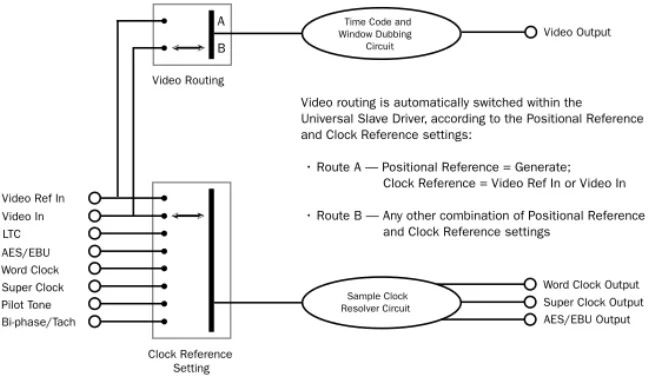
Video In/Out
Video In Receives a signal from an NTSC/PAL video source for clock or VITC positional refer-ence input, or for generating a window burn. This connector is internally terminated at 75 ohms.
Video Out Output of the current Video In signal. If the Positional Reference is set to Generate and the Clock Reference is set to one of the two video inputs, this will output a copy of the video Figure 2. SYNC I/O Back Panel
MTC OUT HOST SERIAL
AC 100-240V, 50-60HZ, .5A 30W
VIDEO REF 9-PIN OUT 2
9-PIN OUT 1 WORD CLOCK (1x,256x) VIDEO L T C I N A E S I N A E S O U T L T C O U T IN OUT IN OUT IN OUT LOOP SYNC INTERNALLY TERMINATED
BI-PHASE / TACH / GPI / PILOT SERIAL NUMBER 964530300294856
Video Ref
Bi-Phase/Tach
Video Word Clock
AC Power Host Serial
GPI/Pilot
In/Out
Loop Sync LTC In/Out AES In/Out
In/Out
MTC Out 9-Pin Out 1
In/Out
9-Pin Out 2 In/Out
Refer to Appendix C, “Wiring Diagrams Pin Assignments” for wiring information and other specifications for this port.
If SYNC I/O is the last device in the video sync chain, a BNC terminator (supplied) must be attached to this connector.
Chapter 3: SYNC I/O Hardware and Software Overview 27
signal appearing at the Video Reference input. In either case, this output might additionally carry VITC and/or Window Burn information if those features are enabled.
MTC Out
Outputs MIDI Time Code (MTC), only. No other MIDI data appears at this output. MTC output can be regenerated while SYNC I/O is locked to any supported positional reference and clock reference, or internally generated in Generate mode, in which case MTC output follows gener-ator run/stop. This port is intended to supply MTC from SYNC I/O to external sequencers or other MIDI devices.
LTC In/Out
LTC In Receives a Linear Time Code (LTC) source, balanced or unbalanced analog, for clock and positional reference. This port is often used to receive LTC from an audio track on an external deck or the address track of a VTR. Ad-justable LTC servo gain is available in Pro Tools and from the front panel.
LTC Out Outputs linear time code, in balanced or unbalanced analog audio format. See Appendix C, “Wiring Diagrams Pin Assign-ments” for wiring details. LTC output gain is also adjustable from the front panel and from the SYNC I/O Setup software.
AES/EBU In/Out
AES In Receives an AES/EBU digital audio signal, for clock reference purposes only. SYNC I/O uti-lizes only the signal's clock information, not the audio information. If digital audio information is present at this input, it will be ignored and not passed through to the AES/EBU digital out-put connector.
AES/EBU Out Outputs a silent (all bits OFF) AES/EBU audio signal whose sample rate exactly matches SYNC I/O Word Clock BNC output.
Word Clock In/Out
Word Clock In Receives (1x sample rate) Word Clock, for clock reference purposes only. Word Clock is often used with external digital con-soles and digital tape machines.
Word Clock Out Outputs 1x sample rate Word Clock information, or 256x Slave Clock, to pro-vide clock to HD-series audio interfaces, Legacy peripherals, and other Word clock-capable de-vices. This port is configured from the front panel, or using SYNC I/O Setup, by adjusting the SYNC I/O Base Clock setting.
9-pin Out 1 and 2
For Digidesign MachineControl-enabled sys-tems, these two ports connect directly to
exter-nal 9-pin transport devices. See the
Machine-Control Guide for more information.
Loop Sync In/Out
Loop Sync is the clock signal used to synchro-nize Pro Tools|HD-series audio interfaces.
Loop Sync In Receives Loop Sync from any HD-series audio interface.
Loop Sync Out Provides Loop Sync. This port connects to the primary HD-series audio inter-face.
AC Power In
Receives AC mains power, 85 to 264 volts, 47 to 63 Hz (auto switching).
SYNC I/O Setup Software
The following is an overview of SYNC I/O Setup. System and installation requirements for SYNC I/O Setup can be found in “Software In-stallation” on page 14.
Using Help
To activate Help:
■ Choose Help > Show Help, or click on the
question mark button in the upper-right corner of the SYNC I/O Setup window.
To deactivate Help:
■ Choose Help > Hide Help, or click the
ques-tion mark button again.
Overview of SYNC I/O Setup
The following section identifies SYNC I/O Setup controls and displays.
Time Code Window
The time code display mirrors the LED Time Code Display on the SYNC I/O front panel, dis-playing (in hours:minutes:seconds:frames) the time code address of the current positional ref-erence.
When SYNC I/O is reading odd-numbered fields, the separator changes from a normal co-lon (:) to a period (.); when it’s reading even-numbered fields, the punctuation returns to a colon (:). Odd/even status is only available while reading VITC, and only when VITC is within a speed range from zero to about 50% of playback speed.
Clock Reference
Selects SYNC I/O clock reference.
Sample Rate
Selects SYNC I/O sample rate (or the Pro Tools session sample rate, if applicable).
Pull Rate
Enables Pull Up or Pull Down for the current sample rate.
User Sync Out
Configures the base clock of the External Clock Output for 1x (session sample rate) or 256x (for Slave Clock devices only).
Word Clock Out
Configures the SYNC I/O Word Clock Output between 256x (Super Clock) and the current ses-sion rate (1x at 44.1 kHz, or 1x at 48 kHz). Only Legacy audio interface require 256x Super Clock.
Chapter 3: SYNC I/O Hardware and Software Overview 29
Positional Reference
Selects SYNC I/O positional reference.
Frame Rate
Selects the frames-per-second (fps) rate of exter-nal (or interexter-nally generated) time code.
Status
Shows the current state of SYNC I/O Setup soft-ware in relation to SYNC I/O and external de-vices, as follows:
Resolver Locked Lights when SYNC I/O is locked to the chosen external clock reference, or
to its Internal clock reference.
Speed Calibration Lights when SYNC I/O sys-tem clock and all output clocks are at a fre-quency that corresponds with the chosen sam-ple rate. Capable of indicating mismatch of pull-up, pull-down and frame rate.
Generator Running Lights when SYNC I/O is re-generating time code at its video, LTC, and MTC outputs locked with the incoming positional reference source. Also lit whenever SYNC I/O is generating time code internally.
Connected to SYNC I/O Lights when SYNC I/O Setup is the front-most window and is commu-nicating with SYNC I/O.
Waiting for SYNC I/O Lights when SYNC I/O Setup is the front-most window and is unable to communicate with SYNC I/O.
Port Relinquished Lights when SYNC I/O Setup is not the front-most window or is unable to al-locate a serial port with which to communicate with SYNC I/O.
LTC Output Level
Adjusts the analog audio level of the SYNC I/O LTC output, from –24 dBu to +9 dBu.
Freewheel Duration
Sets the period of time for which SYNC I/O will continue to supply positional reference data af-ter an exaf-ternal source is inaf-terrupted or stopped (also referred to as Time Code Freewheel in Pro Tools).
Video Format
Selects the format (NTSC or PAL) for both the in-coming and outgoing video signals.
◆ NTSC is used in North and South America,
Ja-pan, and certain other parts of the world.
◆ PAL is used in most of Europe, Asia, and
Af-rica. Users of SECAM video (for France, Russia, and certain other parts of the world) should se-lect PAL.
VITC Read Lines
Determines which line pair of incoming video signal is used for the VITC source. When set to Auto, SYNC I/O will search for the first valid line pair automatically. Alternatively, this value can be set to specific VITC line pairs.
VITC Generate Lines
Determines the line pair of the outgoing video signal onto which SYNC I/O inserts VITC. Nor-mally, this should be left at the default (and pre-ferred) setting of 14/16.
For details about Speed Calibration charac-teristics, see “Status LEDs” on page 25.