Vivado Design Suite
User Guide:
Logic Simulation
Notice of Disclaimer
The information disclosed to you hereunder (the “Materials”) is provided solely for the selection and use of Xilinx products. To the maximum extent permitted by applicable law: (1) Materials are made available "AS IS" and with all faults, Xilinx hereby DISCLAIMS ALL WARRANTIES AND CONDITIONS, EXPRESS, IMPLIED, OR STATUTORY, INCLUDING BUT NOT LIMITED TO WARRANTIES OF MERCHANTABILITY,
NON-INFRINGEMENT, OR FITNESS FOR ANY PARTICULAR PURPOSE; and (2) Xilinx shall not be liable (whether in contract or tort, including negligence, or under any other theory of liability) for any loss or damage of any kind or nature related to, arising under, or in connection with, the Materials (including your use of the Materials), including for any direct, indirect, special, incidental, or consequential loss or damage (including loss of data, profits, goodwill, or any type of loss or damage suffered as a result of any action brought by a third party) even if such damage or loss was reasonably foreseeable or Xilinx had been advised of the possibility of the same. Xilinx assumes no obligation to correct any errors contained in the Materials or to notify you of updates to the Materials or to product specifications. You may not reproduce, modify, distribute, or publicly display the Materials without prior written consent. Certain products are subject to the terms and conditions of the Limited Warranties which can be viewed at http://www.xilinx.com/warranty.htm; IP cores may be subject to warranty and support terms contained in a license issued to you by Xilinx. Xilinx products are not designed or intended to be fail-safe or for use in any application requiring fail-safe performance; you assume sole risk and liability for use of Xilinx products in Critical Applications:
http://www.xilinx.com/warranty.htm#critapps.
© Copyright 2012 Xilinx, Inc. Xilinx, the Xilinx logo, Artix, ISE, Kintex, Spartan, Virtex, Zynq, and other designated brands included herein are trademarks of Xilinx in the United States and other countries. All other trademarks are the property of their respective owners.
Revision History
The following table shows the revision history for this document.
Date Version Revision
Table of Contents
Revision History . . . 2
Chapter 1: Logic Simulation Overview
Introduction . . . 5Simulation Flow . . . 5
Simulation Modes of Operation . . . 9
Supported Simulators . . . 11
Vivado Simulator Features . . . 12
Language Support . . . 12
OS Support and Release Changes . . . 12
Simulation Libraries . . . 13
Chapter 2: Understanding Vivado Simulation Components
Introduction . . . 14About Test Benches or Stimulus Files. . . 14
About Simulation Libraries . . . 16
Netlist Generation Process in Non-Project Mode . . . 24
About Global Reset and Tristate for Simulation . . . 26
Chapter 3: Running Simulation in Vivado IDE
Introduction . . . 28Using Simulation Settings . . . 28
Managing Simulation Sources. . . 32
Using the Vivado Simulator. . . 36
Pausing a Simulation . . . 40
Saving Simulation Results . . . 41
Closing Simulation . . . 41
Chapter 4: Compiling and Simulating the Design
Introduction . . . 42Parsing Design Files . . . 43
Elaborating and Generating a Snapshot Using xelab. . . 44
Project File Syntax . . . 50
Predefined XILINX_SIMULATOR Macro for Verilog Simulation . . . 51
Simulating the Design in Non-Project Mode . . . 51
Library Mapping File (xsim.ini) . . . 54
xelab, xvhd, and xvlog Command Options. . . 55
Using Mixed Language Simulation . . . 58
Chapter 5: Analyzing and Debugging With Waveforms
Introduction . . . 62Launching the Vivado Simulator . . . 63
Adding HDL Objects to the Wave Configuration . . . 63
Using Non-Project Mode . . . 68
Understanding HDL Objects in Waveform Configurations . . . 69
About Wave Configurations and Waveform Windows . . . 70
Controlling the Display of Waveforms . . . 71
Customizing the Wave Configuration . . . 80
Viewing Simulation Data from Prior Simulation Settings (Static Simulation) . . . 86
Debugging at the Source Level . . . 88
Appendix A: Running Simulation with Third Party Simulators Outside Vivado IDE
Introduction . . . 91Running RTL/Behavioral Simulation . . . 91
Running Netlist Simulation . . . 92
Running Timing Simulation . . . 93
Appendix B: Verilog and VHDL Exceptions
Introduction . . . 94VHDL Language Support Exceptions . . . 94
Verilog Language Support Exceptions . . . 96
Appendix C: Additional Resources
Xilinx Resources . . . 99Solution Centers. . . 99
Chapter 1
Logic Simulation Overview
Introduction
Simulation is a process of emulating the real design behavior in a software tool. A
simulation helps verify the functionality of a design by injecting stimulus and observing the design outputs. Simulators interpret VHDL or Verilog code into circuit functionality, and display logical results.
This document describes the simulation options available using the Xilinx® Vivado™
Integrated Design Environment (IDE).
This chapter provides an overview of the simulation process, and the simulation tool options in the Vivado IDE. The Vivado IDE is designed to be used with several HDL
simulation tools that provide a solution for programmable logic designs from beginning to end.
Simulation Flow
Simulation can be applied at several points in the design flow. It is one of the first steps after design entry and one of the last steps after implementation as part of the verifying the end functionality and performance of the design.
Simulation is an iterative process; it might need to be repeated until both the design functionality and the timing are met.
Simulation Flow
X-Ref Target - Figure 1-1
Behavioral Simulation at the Register Transfer Level
Register Transfer Level (RTL), behavioral simulation can include: • RTL Code
• Instantiated UNISIM library components
• Instantiated UniMacro components
• XilinxCoreLib and UNISIM gate-level models (for the Vivado logic analyzer) X-Ref Target - Figure 1-2
Figure 1-1: Simulation Flow
24,$ESIGN 0OST3YNTHESIS3IMULATION 0OST)MPLEMENTATION3IMULATION #LOSETO%MULATING(7 3YNTHESIZE )MPLEMENT0LACEAND2OUTE $EBUGTHE$ESIGN 3IMULATION&LOW "EHAVIORAL3IMULATION 6ERIFY$ESIGN"EHAVESAS)NTENDED
Simulation Flow
The RTL-level simulation lets you verify or simulate a description at the system or chip level. This first pass simulation is typically performed to verify code syntax, and to confirm that the code is functioning as intended. At this step, no timing information is provided, and simulation is performed in unit-delay mode to avoid the possibility of a race condition. RTL simulation is not architecture-specific unless the design contains instantiated UNISIM
or Lab Analyzer components. To support these instantiations, Xilinx® provides the UNISIM
and XilinxCoreLib libraries. You can use the Vivado Lab Analyzer components if you do
not want to rely on the module generation capabilities of the synthesis tool, or if the design requires larger structures.
When you verify your design decisions before the design is being implemented at the behavioral RTL you can make any necessary changes earlier and save design cycles.
TIP: Keep the code behavioral for the initial design creation. Do not instantiate specific components unless necessary. You might find it necessary to instantiate components if the component is not inferable.
Keeping the initial design creation limited to behavioral code allows for: • More readable code
• Faster and simpler simulation
• Code portability (the ability to migrate to different device families) • Code reuse (the ability to use the same code in future designs)
Post-Synthesis Simulation
You can simulate a synthesized netlist to verify the synthesized design meets the functional requirements and behaves as expected.
Although it is not typical, you do have the capability to perform timing simulation with estimated timing numbers at this simulation point.
The functional simulation netlist is a hierarchical, folded netlist expanded to the primitive module and entity level; the lowest level of hierarchy consists of primitives and macro primitives. These primitives are contained in the UNISIMS_VER library for Verilog, and the UNISIM library for VHDL. See UNISIM Library, page 17 for more information.
Simulation Flow
Post-Implementation Simulation
You can perform functional or timing simulation after implementation. Timing simulation is the closest emulation to actually downloading a design to a device. It allows you to ensure that the implemented design meets functional and timing requirements and has the expected behavior in the device.
Performing a thorough timing simulation ensures that the completed design is free of defects that could otherwise be missed, such as:
• Post-synthesis and post-implementation functionality changes that are caused by:
° Synthesis attributes or constraints that create mismatches
(such as full_case and parallel_case)
° UNISIM attributes applied in the Xilinx Design Constraints (XDC) file ° The interpretation of language during synthesis by different simulators
• Dual port RAM collisions
• Missing, or improperly applied timing constraints • Operation of asynchronous paths
• Functional issues due to optimization techniques
See About Post-Synthesis or Post-Implementation Timing Simulation, page 54 for more information.
Simulation Modes of Operation
Simulation Modes of Operation
The Vivado simulator has two modes of operation: Project Mode and Non-Project Mode.
Project Mode: Using the Graphical User Interface (GUI)
When you run simulation using a project in the Vivado IDE, the Vivado simulator GUI opens and provides a graphical view of simulation data. You can use menu commands and toolbar buttons to run simulation, examine the design, and debug data.
In Project Mode, you can: • Open or create a project. • Create or add a test bench.
See About Test Benches or Stimulus Files.
• From the Simulation section of the Flow Navigator in the Vivado IDE, select the
Simulation Settings to select and setup the simulation options.
See Using Simulation Settings and Managing Simulation Sources in Chapter 3. • Click the Run Simulation button in the Flow Navigator to launch behavioral RTL
simulation.
• Refer to Vivado IDE execution, error, and log messages. See Chapter 3, Running Simulation in Vivado IDE.
• Analyze and debug your design with the Vivado IDE common waveform viewer. See Chapter 5, Analyzing and Debugging With Waveforms.
Simulation Modes of Operation
Using Non-Project Mode: Command and Batch Script Options
In Non-Project Mode, you can:
• Create or add a test bench for functional RTL, post-synthesis, or post-implementation simulation.
Note: Post-synthesis and post-implementation simulation is supported in Non-Project Mode
only.
• Specify source files, libraries, and file compilation order.
• Parse and elaborate a design using the Vivado simulator commands. See Chapter 4, Compiling and Simulating the Design.
• Run the Vivado simulator.
• Debug the design using the Vivado simulator waveform viewer.
See Chapter 4, Compiling and Simulating the Design for more information.
See Appendix A, Running Simulation with Third Party Simulators Outside Vivado IDE.
IMPORTANT: In Non-Project Mode, you must manage your source files.
Figure 1-3 illustrates the simulation flow in Non-Project Mode.
X-Ref Target - Figure 1-2
Supported Simulators
X-Ref Target - Figure 1-3
Supported Simulators
The supported simulators are: • Vivado simulator
• Mentor Graphics QuestaSim/ModelSim (integrated in the Vivado IDE) • Cadence Incisive Enterprise Simulator (IES)
• Synopsys VCS and VCS MX • Aldec Active-HDL*
• Aldec Rivera-PRO*
Note: (* Aldec simulators are compatible but not supported by Xilinx Technical Support.
Contact your Aldec representative for any support issues.)
Figure 1-3: Simulation Flow in Non-Project Mode
#OLLECT&ILES 3PECIFY#OMPILE/RDER6($, 0ARSEAND%LABORATE&ILES XLOGXVHDANDXELABCOMMANDS 2UN3IMULATIONXSIM #REATEAND)NCLUDE4EST"ENCH .ON0ROJECT-ODE $EBUG
Vivado Simulator Features
Vivado Simulator Features
The Vivado simulator supports the following features: • Source code debugging
• SDF annotation • VCD dumping
• SAIF dumping for power analysis and optimization
• Native support for HardIP blocks (such as MGT, PPC, and PCIe®)
• Multi-threaded compilation
• Mixed language (VHDL and Verilog) use
• Single-click simulation re-compile and re-launch • One-click compilation and simulation
• Built-in Xilinx® simulation libraries
The Xilinx Design Tools: Release Notes Guide (UG631) [Ref 1] lists the currently supported simulator versions.
Note: Third party simulators (with the exception of QuestaSim/ModelSim, which can be selected
and invoked from the Vivado IDE) must be run outside of the Vivado IDE.
Language Support
The following languages are supported: • VHDL IEEE-STD-1076-1993
• Verilog IEEE-STD-1364-2001
• Standard Delay Format (SDF) version 2.1 • VITAL-2000
OS Support and Release Changes
The Xilinx Design Tools: Release Notes Guide (UG631) [Ref 1] provides information about the most recent release changes.
See the Xilinx Design Tools: Installation and Licensing Guide (UG798)[Ref 2] for operating systems support.
Simulation Libraries
Simulation Libraries
The libraries required to support simulation flows are: • SIMPRIM_VER - Verilog UNISIM with timing
• XILINXCoreLib- VHDL IP
• XILINXCORELIB_VER - Verilog IP
• UNISIM - VHDL UNISIM
• UNISIMS_VER - Verilog UNISIM
• UNIMACRO - VHDL UNIMACRO
• UNIMACRO_VER - Verilog UNIMACRO
• SECUREIP - Verilog Hard IP
• UNIFAST - Fast simulation VHLD library
• UNIFAST_VER - Fast simulation Verilog library
About Simulation Libraries in Chapter 2 describes the simulation libraries. Also, see the 7 Series FPGA Libraries Guide for HDL Designs (UG768) [Ref 6].
Note: The Vivado simulator uses precompiled simulation device libraries and updates those libraries
automatically when updates are installed.
Table 1-1 lists the points of simulation and which simulation library is used at that simulation point.
See Chapter 2, Understanding Vivado Simulation Components, for more information about simulation libraries.
Table 1-1: Simulation Points and Relevant Libraries
UNISIM Unifast UniMacro XilinxCoreLib Models SecureIP (Verilog Only)SIMPRIM
Standard Delay Format (SDF) 1. Register Transfer Level
(RTL) Yes Yes Yes Yes Yes N/A Yes 2.
Post-Synthesis
Simulation Yes Yes N/A N/A Yes Yes Yes 3.
Post-Implementation
Chapter 2
Understanding Vivado Simulation
Components
Introduction
This chapter describes the components that you need when you simulate a Xilinx® FPGA in
the Vivado™ Integrated Design Environment (IDE).
Note: Simulation libraries are precompiled in the Vivado Design Suite for use with the Vivado
simulator. You must compile libraries when using third party simulators.
The process of simulation includes:
• Creating a test bench that reflects the simulation actions you want to run • Selecting and declaring the libraries you need to use
• Compiling your libraries (if using a third-party simulator)
• Writing a netlist (if performing Post-Synthesis or Post-Implementation simulation) • Understanding the use of global reset and tristate in Xilinx devices
The following sections describe these required components.
About Test Benches or Stimulus Files
A test bench is Hardware Description Language (HDL) code written for the simulator that does the following:
• Instantiates the design • Initializes the design
• Generates and applies stimulus to the design
About Test Benches or Stimulus Files
You can also set up the test bench to display the simulation output to a file, a waveform, or to a display screen. A test bench can be simple in structure and sequentially apply stimulus to specific inputs.
A test bench can also be complex, and can include: • Subroutine calls
• Stimulus that is read in from external files • Conditional stimulus
• Other more complex structures
A test bench has the following advantages over interactive simulation: • It allows repeatable simulation throughout the design process. • It provides documentation of the test conditions.
TIP: Choose Vivado simulator as the target simulator in GUI
(see Using Simulation Settings in Chapter 3) and click Run Simulation.
This creates a <testbench>.prj file in the project/project.sim/sim_1 directory, which has
the collection of all the sources needed to simulate the design. Use that file as starting point for gathering files.
The following bullets are recommendations for creating an effective test bench.
• Specify the name as testbench to the main module or entity name in the test bench
file.
• Always specify the `timescale in Verilog test bench files.
• Initialize all inputs to the design within the test bench at simulation time zero to properly begin simulation with known values.
• Apply stimulus data after 100 ns to account for the default Global Set/Reset (GSR) pulse used in UNISIM and SIMPRIM-based simulation.
• Begin the clock source before the Global Set/Reset (GSR) is released.
For more information, see About Global Reset and Tristate for Simulation, page 26. For more information about test benches, refer to the Writing Efficient TestBenches (XAPP199) application note [Ref 5].
About Simulation Libraries
About Simulation Libraries
When you instantiate a component in your design, the simulator must reference a library that describes the functionality of the component to ensure proper simulation.
Table 2-1 lists the Xilinx-provided simulation libraries:
It is important to note that:
• You must specify different simulation libraries according to the simulation points. • There are different gate-level cells in pre- and post-implementation netlists.
Table 2-2 lists the required simulation libraries at each simulation point.
Table 2-1: Simulation Libraries
Library Name Description VHDL Verilog
UNISIM Functional simulation of Xilinx
primitives. unisim unisims_ver UniMacro Functional simulation of Xilinx macros. unimacro unimacro_ver
UniFast Fast simulation library. unifast unifast_ver
XilinxCoreLib Functional simulation of Xilinx cores. xilinxcorelib xilinxcorelib_ver
SIMPRIM Timing simulation of Xilinx primitives. N/A SIMPRIM_VER
SecureIP Simulation library for both functional and timing simulation of Xilinx device features, such as the:
• PowerPC® processors
• PCIe® technology
• Gigabit Transceiver • Ethernet MAC
secureip -lib secureip
Table 2-2: Libraries Required in Simulation Points
Simulation Point Required Library
Register Transfer Level (RTL) UNISIM Unifast UniMacro XilinxCoreLib SecureIP
About Simulation Libraries
Note: Verilog SIMPRIM uses the same source as UNISIM with the addition of specify blocks for
timing annotation. This is enabled by `ifdef XIL_TIMING in UNISIM source code. Table 2-3 lists the library locations.
The following subsections describe the libraries in more detail.
UNISIM Library
The UNISIM library is used during functional simulation and contains descriptions for all
the device primitives, or lowest-level building blocks.
VHDL UNISIM Library
The VHDL UNISIM library is divided into the following files: • The component declarations (unisimVCOMP.vhdl)
• Package files (unisim_VPKG.vhd)
• Entity and architecture declarations (unisim_VITAL.vhdl)
Primitives for Xilinx device families are specified in these files.
Post-Synthesis Simulation UNISIM (Functional Netist) SIMPRIM (Timing Netlist) SecureIP
Post-Implementation
Simulation UNISIM (Functional Netlist)SIMPRIM (Timing Netlist) SecureIP
Table 2-2: Libraries Required in Simulation Points (Cont’d)
Simulation Point Required Library
Table 2-3: Simulation Library Locations Library HDL
Type Location
UNISIM Verilog <Xilinx Install>/PlanAhead/data/verilog/unisims
VHDL <Xilinx Install>/PlanAhead/data/vhdl/unisims
UNIFAST Verilog <Xilinx Install>/PlanAhead/data/verilog/unifast
VHDL <Xilinx Install>/PlanAhead/data/vhdl/unifast
UNIMACRO Verilog <Xilinx Install>/PlanAhead/data/verilog/unimacro
VHDL <Xilinx Install>/PlanAhead/data/vhdl/unimacro
SecureIP Verilog <Xilinx Install>
About Simulation Libraries
To use these primitives, place the following two lines at the beginning of each file:
library UNISIM;
use UNISIM.Vcomponents.all;
You must also compile the library and map the library to the simulator. The method depends on the simulator.
Note: For Vivado simulator, the library compilation and mapping is built-in.
Verilog UNISIM Library
For Verilog, specify each library component is in a separate file. This allows the Verilog -y
library specification switch to perform automatic library expansion. Specify Verilog module names and file names in upper case.
For example, module BUFG is BUFG.v, and module IBUF is IBUF.v.
See Appendix A, Running Simulation with Third Party Simulators Outside Vivado IDE for examples that use the -y switch.
Note: Verilog is case-sensitive, ensure that UNISIM primitive instantiations adhere to an upper-case
naming convention.
If you are using precompiled libraries, use the correct simulator command-line switch to point to the precompiled libraries. The following is an example for the Vivado simulator:
-L unisims_ver
UniMacro Library
The UniMacro library is used during functional simulation and contains macro descriptions for selective device primitives. You must specify the UniMacro library anytime you include a device macro listed 7 Series FPGA Libraries Guide for HDL Designs (UG768) [Ref 6].
VHDL UniMacro Library
Add the following library declaration to the top of your HDL file:
library UNIMACRO;
use UNIMACRO.Vcomponents.all;
Verilog UniMacro Library
For Verilog, specify each library component in a separate file. This allows automatic library expansion using the -y library specification switch.
About Simulation Libraries
IMPORTANT: Verilog module names and file names are uppercase. For example, module BUFG is BUFG.v, and module IBUF is IBUF.v. Ensure that UNISIM primitive instantiations adhere to an
uppercase naming convention.
You must also compile and map the library: the method you use depends on the simulator. The following is an compilation and mapping example for the Vivado simulator:
-L unimacro_ver
XilinxCoreLib Library
Use the XilinxCoreLib library during RTL Behavioral simulation for designs that contain
certain cores created by the Xilinx IP catalog.
SIMPRIM Library
Use the SIMPRIM library for simulating timing simulation netlists produced after synthesis
or implementation.
IMPORTANT: Timing simulation is supported on Verilog only; there is no VHDL version of the SIMPRIM library.
Specify this library as follows:
-L SIMPRIM_VER
Where:
° -L is the library specification command.
° SIMPRIM_VER is the logical library name to which the Verilog UniMacro has been
mapped.
SecureIP Simulation Library
Use the SecureIP library for functional and timing simulation of complex FPGA
components, such as: PPC and GT.
Note: IP Blocks are fully supported in the Vivado simulator without additional setup.
Xilinx leverages the encryption methodology as specified in Verilog LRM - IEEE Std 1364.2001. The library compilation process automatically handles encryption.
When running a simulation using Verilog code, you must reference the SecureIP library.
For most simulators, this can be done by using the -L switch as an argument to the
About Simulation Libraries
-L SECUREIP_VER.
Note: See the simulator documentation for the command-line switch to use with your simulator to
specify libraries.
Table 2-4 lists special considerations that must be arranged with your simulator vendor for using these libraries.
VHDL SecureIP Library
To use SecureIP in VHDL, place the following two lines at the beginning of each file:
Library UNISIM;
use UNISIM.vcomponents.all;
Verilog SecureIP Library
You can use the Verilog SecureIP library at compile time by leveraging the -f switch. The
following is a command-line example for VCS:
vcs -f <Xilinx Install>/PlanAhead/data/secureip/VCS/vcs_cell.list.f \ <other simulation commands>
If you are use the precompiled libraries, use the correct directive to point to the precompiled libraries. The following is an example for the Vivado simulator:
-L SECUREIP_VER
UNIFAST Library
The UNIFAST library is an optional library that can be used during RTL behavioral
simulation to speed up simulation runtime. The simulation runtime speed up is achieved by supporting a subset of the primitive features in the simulation model.
Fast MMCME2 UNISIM Simulation Model
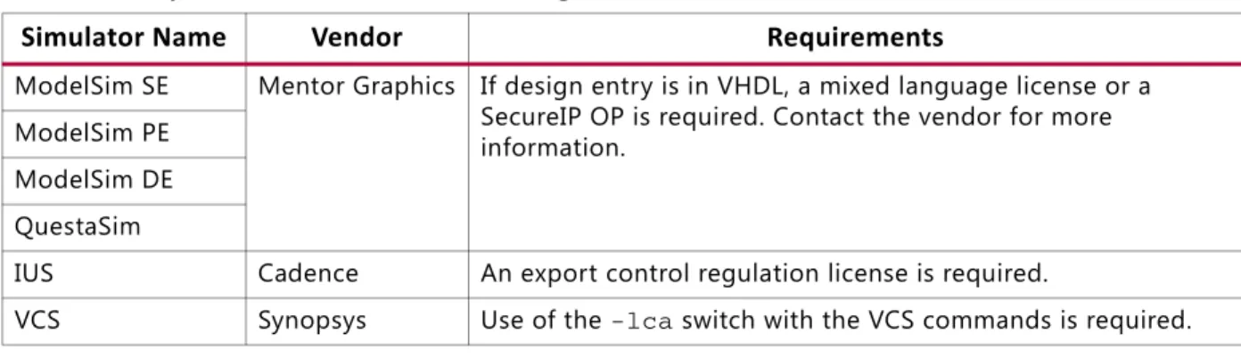
Table 2-4: Special Considerations for Using SecureIP Libraries
Simulator Name Vendor Requirements
ModelSim SE Mentor Graphics If design entry is in VHDL, a mixed language license or a SecureIP OP is required. Contact the vendor for more information.
ModelSim PE ModelSim DE QuestaSim
IUS Cadence An export control regulation license is required.
About Simulation Libraries
1. The fast simulation model just has basic clock generation function. All other functions; such as DRP, fine phase shifting, clock stopped, and clock cascade are not supported. 2. It assumes that input clock is stable without frequency and phase change. The input
clock frequency sample stops after LOCKED high.
3. The output clock frequency, phase, duty cycle, and other features are directly calculated from input clock frequency and parameter settings.
Note: The output clock frequency is not generated from input to VCO clock, then VCO to output
clocks.
4. The LOCKED assert times are different between the standard and the fast MMCME2
simulation model.
° Standard Model depends on the M the D setting, for large M and D values, the lock
time is relatively long for standard MMCME2 simulation model. ° In fast simulation model, this time is shortened.
RAMB18E1/RAMB36E1
To reduce the simulation runtimes, a fast Block RAM simulation model has the following features removed from the full model:
• Error Correction Code (ECC) • Collision checks
• Cascade mode
FIFO18E1/FIFO36E1
To reduce the simulation runtimes, a fast FIFO simulation model has the following features removed from the full model:
• ECC
• Design Rules Check (DRC) for RESET
• DRC check for almostempty and almostfull offset
• Output padding – X for data out, 1 for counters
• First word fall-through
• almostempty and almostfull flags
DSP48E1
To reduce the simulation runtimes, a fast DSP48E1 simulation model has the following features removed from the full model:
About Simulation Libraries
• ALU
• Pattern Detect
OverFlow/UnderFlow
To reduce the simulation runtimes, a fast OverFlow/UnderFlow simulation model has the following features removed from the full model:
• PLLE2_ADV
• DRP interface support
Using Verilog UNIFAST Library
Method 1: Configurations in Verilog
In method 1, the following are specified in a config.v file.
• Specify the name of the top-level module or configuration (for example: config cfg_xilinx;)
• Specify the name to which the design configuration applies (for example: design testbench;)
• Define the library search order for cells or instances that are not explicitly called out (for example: default liblist unisims_ver unifast_ver;)
• Map a particular CELL or INSTANCE to a particular library
(for example: instance testbench.inst.O1 use unifast_ver.OR2;) Note: For ModelSIM (vsim) only - genblk gets added to hierarchy name
(for example: instance testbench.genblk1.inst.genblk1.O1 use unifast_ver.OR2; - VSIM)
Example config.v
config cfg_xilinx; design testbench;
default liblist unisims_ver unifast_ver; cell AND2 use unifast_ver.AND2;
instance testbench.inst.O1 use unifast_ver.OR2;
(instance testbench.genblk1.inst.genblk1.O1 use unifast_ver.OR2; - VSIM) endconfig
Method 2: Using Library or File Compile Order
This second method lists the compile order by simulator and code type:
About Simulation Libraries
xvlog -sourcelibdir ../verilog/src/unifast -sourcelibext .v -sourcelibdir ../verilog/src/unisims; xelab testbench glbl -s mysim
• Modelsim - Verilog -L or -y order selects all fast / no fast. vsim -c -L unifast_ver -L unisims_ver testbench glbl
vlog -y ../verilog/src/unifast +libext+.v -y ../verilog/src/unisims; vsim -c testbench glbl
• NCSIM - Verilog - same results with different command lines. ncelab -libname unifast_ver -libname unisims_ver
ncverilog -y ../verilog/src/unifast +libext+.v -y ../verilog/src/unisims +libext+.v \
• VCS - Verilog -lib does not imply order - change synopsys_sim.setup
to order libraries
vcs -work work -y ../Verilog/src/unifast +libext+.v -y ../verilog/src/unisims +libext+.v ../netlist.v testbench glbl
Using VHDL UniFast Library
The VHDL UniFast library has the same basic structure as Verilog and can be used with
architectures or libraries. This library can be included in the test bench file. The following example uses a "drill-down" hierarchy with a for call:
library work; library unisim;
library unifast; -- (different libs use case)
configuration cfg_xilinx of testbench is for xilinx for inst:netlist use entity work.netlist(inst); for inst
for all:AND2 use entity unifast.AND2; -- could be unisim.AND2(fast) (architecture use case) end for;
for O1:OR2 use entity unifast.OR2; -- could be unisim.OR2(fast) (architecture use case)
end for;
end for; end for; end for; end cfg_xilinx;
Compiling Simulation Libraries
Before you can simulate your design, you must compile the applicable libraries and map them to the simulator.
Use the compile_simlib Tcl command in the Vivado Design Suite Tcl Console for
compiling Xilinx HDL-based simulation libraries for third party simulation vendors. Libraries are typically compiled (or recompiled) anytime a new simulator version is installed.
Netlist Generation Process in Non-Project Mode
TIP: When you use testbench as the test bench name, compilation changes are necessary to perform
simulation from the Vivado IDE.
Netlist Generation Process in Non-Project Mode
To run simulation of a Synthesized or Implemented design run the netlist generation pro-cess. The netlist generation Tcl commands can take a synthesized or implemented design database and write out a single netlist for the entire design.
Netlist generation Tcl commands can write simulation, STA, and the design netlist. The Vivado Design Suite provides the following netlist Tcl commands:
• write_verilog: Verilog netlist
• write_vhdl: VHDL netlist
• write_sdf: SDF generation
These commands can generate functional and timing simulation netlists at any point in the design process.
TIP: The SDF values only estimates early in the design process (for example, during synthesis) As the design process progresses, the accuracy of the timing numbers also progress when there is more information available in the database.
Generating a Functional Netlist for Simulation
The Vivado Design Suite supports writing out a Verilog or VHDL structural netlist for functional simulation. The purpose of this netlist is to run simulation (without timing information) to check that the behavior of the structural netlist implemented by the Vivado IDE matches the expected behavioral model (RTL) simulation.
The functional simulation netlist is a hierarchical, folded netlist that is expanded to the primitive module or entity level; the lowest level of hierarchy consists of primitives and macro primitives. These primitives are contained in the following libraries:
• UNISIM_VER simulation library for Verilog simulation
• UNISIM simulation library for VHDL simulation
In many cases, you can use the same test bench that you used for behavioral simulation to perform a more accurate simulation.
Netlist Generation Process in Non-Project Mode
The following is the Verilog and VHDL syntax for generating a functional simulation netlist:
write_verilog –mode funcsim <verilogNetlistName> write_vhdl –mode funcsim <vhdlNetlistName>
Generating a Timing Netlist for Simulation
You can use a Verilog timing simulation to verify circuit operation after you have calculated the worst-case placed and routed delays.
In many cases, you can use the same test bench that you used for functional simulation to perform a more accurate simulation.
Compare the results from the two simulations to verify that your design is performing as initially specified.
Note: The Vivado IDE supports Verilog timing simulation only.
The following is the syntax for generating a timing simulation netlist:
write_verilog –mode timesim –sdf_anno true <VerilogNetlistName>
Annotating the SDF File
The following is the syntax for annotating an SDF file:
write_sdf –process_corner fast test.sdf
Running Setup and Hold Checks
Based on the specified process corner, the SDF file has different min and max numbers.
Xilinx recommends running two separate simulations to check for setup and hold violations. To run a setup check, create an SDF with –process corner slow, and use the max column
from the SDF.
For example, in ModelSim, specify:
–sdfmax
To run a hold check, create an SDF with –process corner fast, and use the min column from
the SDF. For example, in ModelSim, specify:
-sdfmin
To get full coverage run all four timing simulations, specify as follows:
·
Slow corner:
SDFMIN
and
SDFMAX
·
Fast corner: SDFMIN and SDFMAX
About Global Reset and Tristate for Simulation
TIP: Ensure that Vivado IDE timing simulation is run with the switches specified in the simulator settings dialog box to prevent pulse swallowing through the Interconnect.
About Global Reset and Tristate for Simulation
Xilinx® devices have dedicated routing and circuitry that connect to every register in the
device.
Global Set/Reset Net
When you assert the dedicated Global Set/Reset (GSR) net, that net is released during configuration immediately after the device is configured. All the flip-flops and latches receive this reset, and are either set or reset, depending on how the registers are defined. Although you can access the GSR net after configuration, Xilinx does not recommend using the GSR circuitry in place of a manual reset. This is because the FPGA devices offer
high-speed backbone routing for high fanout signals such as a system reset. This backbone route is faster than the dedicated GSR circuitry, and is easier to analyze than the dedicated global routing that transports the GSR signal.
In Post-Synthesis and Post-Implementation simulations, the GSR signal is automatically pulsed for the first 100 ns to simulate the reset that occurs after configuration. A GSR pulse can optionally be supplied in Early (Pre-Synthesis) functional simulations, but is not
necessary if the design has a local reset that resets all registers.
TIP: When you create a test bench, remember that the GSR pulse occurs automatically in the
post-synthesis and post-implementation simulation. This holds all registers in reset for the first 100 ns of the simulation.
Global Tristate Net
In addition to the dedicated global GSR, output buffers are set to a high impedance state during configuration mode with the dedicated Global Tristate (GTS) net. All
general-purpose outputs are affected whether they are regular, tristate, or bidirectional outputs during normal operation. This ensures that the outputs do not erroneously drive other devices as the FPGA device is configured.
In simulation, the GTS signal is usually not driven. The circuitry for driving GTS is available in the Post-Synthesis and Post-Implementation simulations and can be optionally added for the Early (Pre-Synthesis) functional simulation, but the GTS pulse width is set to 0 by default.
About Global Reset and Tristate for Simulation
Using Global Tristate (GTS) and Global Set/Reset (GSR) Signals
Figure 2-1 shows how Global Tristate (GTS) and Global Set/Reset (GSR) signals are used in an FPGA device.Global Set/Reset (GSR) and Global Tristate (GTS) in Verilog
The Global Set/Reset (GSR) and Global Tristate (GTS) signals are defined in the
$XILINX/PLANAHEAD/data/verilog/src/glbl.v module. In most cases, GSR and
GTS need not be defined in the test bench.
The glbl.v file declares the global GSR and GTS signals and automatically pulses GSR for
100 ns.
X-Ref Target - Figure 2-1
Figure 2-1: Built-in FPGA Initialization Circuitry Diagram
8 5SER 0ROGRAMMABLE ,ATCH2EGISTER 'LOBAL4RI3TATE '43 5SER/UTPUT )/ 0AD /UTPUT"UFFER )NPUT"UFFER 5SER)NPUT 5SER4RI3TATE %NABLE 'ENERAL0URPOSE )/S5SEDFOR )NITIALIZATION '43 '32 5SER !SYNC 2ESET 'LOBAL 3ET2ESET '32 )NITIALIZATION #ONTROLLER 5SER 0ROGRAMMABLE ,OGIC 2ESOURCES 1 $ #,2 # #%
Chapter 3
Running Simulation in Vivado IDE
Introduction
This chapter describes the Vivado™ Integrated Design Environment (IDE) simulator Graphical User Interface (GUI), which is a selection option when you set up a native mixed language simulator in the Vivado IDE.
The Vivado IDE provides an integrated simulation environment when using the Vivado simulator for behavioral simulation.
Using Simulation Settings
The Flow Navigator > Simulation Settings section lets you configure the simulation settings in Vivado IDE. The Flow Navigator Simulation section is shown in Figure 3-1.
• Simulation Settings: Opens the Simulation Settings dialog box where you can select and configure the Vivado simulator.
• Run Simulation: Sets up the command options to compile, elaborate, and simulate the design based on the simulation settings, then launches the Vivado simulator. The Vivado simulator opens a waveform window hat shows the HDL objects with the signal and bus values in either digital or analog form. See Figure 3-2.
• Open Static Simulation: Lets you open a previously-created waveform configuration (WDB) file. See Viewing Simulation Data from Prior Simulation Settings (Static
Simulation) in Chapter 5.
X-Ref Target - Figure 3-1
Using Simulation Settings
When you select Simulation Settings, the Project Settings dialog box opens, as shown in
Figure 3-2.
The Project Setting dialog box contains the Target Simulator that lets you select the Vivado simulator or QuestaSim/ModelSim.
After you select the simulator, and apply the options from Project Settings, the Simulation dialog box opens, as shown in Figure 3-3, page 30.
IMPORTANT: Because the Vivado simulator has precompiled libraries, it is not necessary for you to identify the library locations. The Simulation dialog box has an additional field for library location
when you select QuestaSim/ModelSim.
X-Ref Target - Figure 3-2
Using Simulation Settings
The Simulation selection options are:
• Simulation set: Select an existing simulation set or use the Create simulation set
option, described in Editing Simulation Sets, page 34.
• Simulation top module name: Set the simulation top module.
• Compiled library location: When you select QuestaSim/ModelSim as the Target Simulator, this field displays the precompiled library.
- See the About Simulation Libraries, page 16 for information about how to specify simulation libraries.
- See Appendix A, Running Simulation with Third Party Simulators Outside Vivado IDE, for more information regarding QuestaSim/ModelSim.
• Compilation View: Provides browse and select options for frequently-used compilation options.
° Verilog options: Select the version of Verilog code to use.
° Generics/Parameters options: Select the required VHDL generics or Verilog
parameters.
X-Ref Target - Figure 3-3
Using Simulation Settings
° Command options:
- -snapshot: Specify a name for the precompiled simulation snapshot to use in
the simulation. A snapshot is the executable output of the simulator compilation process.
- -debug: Is set to typical by default for a faster simulation run.
- -rangecheck: Is set to off by default for a faster simulation run.
• Simulation View: Provides available simulation options. You can select an option to see a description. Figure 3-4 shows the Simulation view:
Select from the following options in the Simulation view:
• Simulation Run Time: Specifies the amount of simulation time to run automatically when the simulation is launched. The defaults is 1000 ns.
• -view: Lets you open a previously-saved wave configuration (WCFG) file. A wave
configuration is a list of HDL objects to display in a waveform window. • More Simulation Options: More simulation options are available.
When you select an option a tooltip provides an option description.
X-Ref Target - Figure 3-4
Managing Simulation Sources
TIP: You can save a WCFG file from an initial run with signals of interest in an analog or digital waveform with dividers and then have the GUI open the WCFG file using the -view option in later runs, which can save time on setting up simulation waveforms.
Managing Simulation Sources
The Vivado Design Suite lets you add simulation sources to the project for RTL behavioral simulation. Simulation source files include Hardware Definition Language (HDL)-based test bench files to use as a stimulus for simulation.
The Vivado Design Suite stores simulation source files in simulation sets, called simsets, that display in folders in the Sources view, and are either remotely referenced or stored in the local project directory.
The simset lets you define different sources for different stages of the design. For example, there can be one simulation source to provide stimulus for behavioral simulation of the
elaborated design or a module of the design, and a different test bench to provide stimulus for timing simulation of the implemented design.
When adding simulation sources to the project, you can specify which simulation source set into which to add files.
Adding or Creating Simulation Source Files
To add simulation sources to a project: 1. Select File > Add Sources.
The Add Sources wizard opens.
2. Select Add or Create Simulation Sources, and click Next.
Managing Simulation Sources
The Add or Create Simulation Sources dialog box options are:
• Specify Simulation Set: Enter the name of the simulation set to test bench files and directories. If there is one or more simulation sets already defined, select the Create Simulation Set command from the drop-down menu to define a new simulation set. • Add Files: Invokes a file browser so you can select simulation source files to add to the
project.
• Add Directories: Invokes directory browser to add all simulation source files from the selected directories. Files in the specified directory with valid source file extensions are added to the project.
• Create File: Invokes the Create Source File dialog box where you can create new simulation source files. See "Adding and Creating Source Files" in the Vivado Design Suite User Guide: Using the Vivado IDE (UG893) [Ref 3] for more information about project source files.
Buttons on the side of the dialog box let you do the following:
• Remove: Removes the selected source files from the list of files to be added. • Move Selected File Up: Moves the file up in the list order.
• Move Selected File Down: Moves the file down in the list order. Checkboxes in the wizard provide the following options:
X-Ref Target - Figure 3-5
Managing Simulation Sources
• Scan and Add RTL Include Files into Project: Scans the added RTL file and adds any referenced include files.
• Copy Sources into Project: Copies the original source files into the project and uses the local copied version of the file in the project.
If you selected to add directories of source files using the Add Directories command, the directory structure is maintained when the files are copied locally into the project. • Add Sources from Subdirectories: Adds source files from the subdirectories of
directories specified in the Add Directories option.
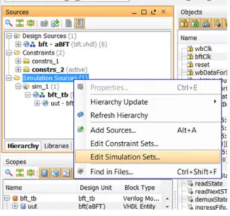
Editing Simulation Sets
To edit a simulation set:
1. In the Sources window popup menu, select Simulation Sources > Edit Simulation Sets, as shown in Figure 3-6.
The Add Sources wizard opens.
2. From the Specify simulation set drop-down, select Create Simulation Set, as shown in
Figure 3-7.
X-Ref Target - Figure 3-6
Managing Simulation Sources
The sources associated with the project are added to the newly-created simulation set. 3. Add additional files as needed.
IMPORTANT: Compilation and simulation setting set for one defined simulation set are not applied to
a newly-defined simulation set: sim_1 compilation and simulation settings do not apply to sim_2,
and so forth.
X-Ref Target - Figure 3-7
Using the Vivado Simulator
Using the Vivado Simulator
When you have selected the Vivado simulator, from the Flow Navigator select Run Simulation. The Vivado simulator GUI, shown in Figure 3-8, opens and displays the simulation.
Understanding the Vivado IDE Simulator Window
The following subsections correspond to the numbered areas of the Vivado simulator.
1. Flow Navigator Simulation Section
The Flow Navigator Simulation section, described in Using Simulation Settings, page 28, is available.
2. Run Menu
The menus provide the same options as the Vivado IDE with the addition of a Run menu after you have run a simulation.
See the Vivado Design Suite User Guide: Using the Vivado IDE (UG893)[Ref 3] for a description
X-Ref Target - Figure 3-8
Using the Vivado Simulator
The Simulation menu options are as follows:
• Restart: Lets you restart an existing simulation time to 0. • Run All: Lets you run an open simulation to completion. • Run For: Lets you specify a time for the simulation to run. • Step: Runs the simulation up to the next HDL source line. • Break: Lets you interrupt a running simulation.
• Delete All Breakpoints: Deletes all breakpoints.
3. Objects Windows
The HDL Objects window displays the HDL objects .
See the Vivado Design Suite User Guide: Using the Vivado IDE (UG893)[Ref 3] for a description of the Sources window.
Buttons beside the HDL objects show the language or process type. This view lists the Name,
Design Unit, and Block Type of the simulation objects. You can hover over the Object buttons for descriptions.
4. Simulation Toolbar
When you run the Vivado simulator, the simulation-specific toolbar opens along with the Vivado toolbars, and displays simulation-specific buttons display for ease-of-use.
When you hover your mouse over the toolbar buttons, a tooltip describes the button function. The buttons are also labeled in Figure 3-9.
X-Ref Target - Figure 3-9
Using the Vivado Simulator
5. and 6. HDL Objects and Waveform Window
The Vivado IDE waveform window is common across a number of Vivado Design Suite tools. See Chapter 5, Analyzing and Debugging With Waveforms for more information about using the waveform.
An example of the waveform window is shown in Figure 3-10.
The waveform window displays HDL objects, their values, and their waveforms, together with items for organizing the HDL objects, such as: groups, dividers, and virtual buses.
Collectively, the HDL objects and organizational items are called wave objects. The waveform portion of the waveform window displays additional items for time measurement, that include: cursors, markers, and timescale rulers.
The Vivado IDE traces the HDL object in the waveform configuration during simulation, and you use the wave configuration to examine the simulation results. The design hierarchy and the waveforms are not part of the wave configuration, and are stored in a separate WDB database file.
When you invoke the simulator, by default, it opens a waveform window that displays a new wave configuration consisting of the traceable top-module of HDL objects in the simulation. The new wave configuration is not saved to disk automatically. Select File > Save Waveform X-Ref Target - Figure 3-10
Using the Vivado Simulator
In a simulation session you can create and use multiple wave configurations, each in its own waveform window. When you have more than one waveform window displayed, the most recently-created or recently-used window is the active window. The active window, in addition to being the window currently visible, is the waveform window upon which commands external to the window, such as the HDL Objects > Add to Wave Window command, apply.
You can set a different waveform window to be the active window by clicking the title of the window.
7. Sources Window
The Sources window displays the simulation sources in a hierarchical tree, with views that show
Hierarchy, IP Sources, Libraries, and Compile Order, as shown in Figure 3-11.
The Sources buttons are described by tooltips when you hover the mouse over them. The buttons let you examine, expand, collapse, add to, open, filter and scroll through files.
X-Ref Target - Figure 3-11
Pausing a Simulation
8. Scopes Window
Figure 3-12 shows the Scopes window, where you can view and filter HDL objects by type using the filter icons at the top of the window. Hover over an icon for a tooltip description of what object type it represents.
See the Vivado Design Suite User Guide: Using the Vivado IDE (UG893)[Ref 3] for a description of the Vivado IDE menus.
See Understanding HDL Objects in Waveform Configurations, page 69 for more detail on how to use the Scopes window in the Vivado simulator.
Pausing a Simulation
While running a simulation for any length of time, you can pause a simulation using the Break
command, which leaves the simulation session open.
To pause a running simulation, select Simulation > Break or click the Break button.
The simulator stops at the next executable HDL line. The line at which the simulation stopped is displayed in the text editor.
Note: This behavior applies to designs that are compiled with the -debug <kind> switch.
The simulation can be resumed at any time by using the Run All, Run, or Step commands. See
Stepping Through a Simulation in Chapter 5 for more information.
X-Ref Target - Figure 3-12
Saving Simulation Results
Saving Simulation Results
The Vivado simulator saves the simulation results of the objects (VHDL signals, or Verilog reg or wire) being traced to the Waveform Database (WDB) file (<filename>.wdb) in the
project/simset directory.
If you add objects to the Wave window and run the simulation, the design hierarchy for the complete design and the transitions for the added objects are automatically saved to the WDB file.
The wave configuration settings; which include the signal order, name style, radix, and color, and so forth; are saved to the wave configuration (WCFG) file upon demand. See Chapter 5, Analyzing and Debugging With Waveforms.
Closing Simulation
To terminate a simulation, select File > Exit or click the X at the top-right corner of the project window.
Chapter 4
Compiling and Simulating the Design
Introduction
Running a simulation from the command line for either a Behavioral or a Timing simulation requires the following steps:
1. Parsing design files
2. Elaboration and generation of a simulation snapshot 3. Simulating the design
The following subsections describe these steps.
There are additional requirements for a Timing simulation, described in the following document areas:
• Generating a Timing Netlist for Simulation in Chapter 2
Parsing Design Files
Parsing Design Files
The xvhdl and xvlog commands parse VHDL and Verilog files, respectively. Descriptions for
each option are available in Table 4-2, page 55. To go to the command description click the option link.
Note: In your PDF reader, turn on the View > Toolbars > More Tools > Previous View and Next View buttons to navigate back and forth.
xvhdl
The xvhdl command is the VHDL analyzer (parser).
xvhdl Syntax
xvhdl [-f [-file] <filename> [-encryptdumps] [-h [-help] [-initfile <init_filename>] [-L [-lib] <library_name>[=<library_dir>]] [-log <filename>] [-nolog] [-prj <filename>] [-relax] [-v [verbose] [0|1|2]] [-work <library_name>[=<library_dir>]…This command parses the VHDL source file(s) and stores the parsed dump into a HDL library on disk.
xvhdl Examples
xvhdl file1.vhd file2.vhd
xvhdl -work worklib file1.vhd file2.vhd xvhdl -prj files.prj
Elaborating and Generating a Snapshot Using xelab
xvlog
The xvlog command is the Verilog parser. The xvlog command parses the Verilog source
file(s) and stores the parsed dump into a HDL library on disk.
xvlog Syntax
xvlog [-d [define] <name>[=<val>]] [-encryptdumps] [-f [-file] <filename> [-h [-help]] [-i [include] <directory_name] [-initfile <init_filename>] [-L [-lib] <library_name>[=<library_dir>]] [-log <filename>] [-nolog] [-relax] [-prj <filename>] [-sourcelibdir <sourcelib_dirname>] [-sourcelibext <file_extension>] [-sourcelibfile <filename>] [-v [verbose] [0|1|2]] [-version]]xvlog Examples
xvlog file1.v file2.v
xvlog -work worklib file1.v file2.v xvlog -prj files.prj
Elaborating and Generating a Snapshot Using xelab
The xelab command, for given top-level units, does the following:
• Loads children design units using language binding rules or the –L <library>
command line specified HDL libraries
• Performs a static elaboration of the design (settles parameters, generics, puts generate statements into effect, and so forth)
• Generates executable code
• Links the generated executable code with the simulation kernel library to create an executable simulation snapshot
You then use the produced executable simulation snapshot name as an option to the xsim
Elaborating and Generating a Snapshot Using xelab
TIP: xelab can implicitly call the parsing commands, xvlog and xvhdl. You can incorporate the
parsing step by using the xelab -prj option. See Project File Syntax, page 50 for more information
about project files.
xelab Command Syntax Options
Descriptions for each option are available in Table 4-2, page 55. To go to the command description click the option link.
Note: In your PDF reader, turn on the View > Toolbars > More Tools > Previous View and Next View buttons to navigate back and forth.
xelab [-d [define] <name>[=<val>] [-debug <kind>] [-f [-file] <filename>] [- generic_top <value>] [-h [-help] [-i [include] <directory_name] [-initfile <init_filename>] [-log <filename>] [-L [-lib] <library_name>[=<library_dir>] [-maxdesigndepth arg] [-mindelay] [-typdelay] [-maxdelay] [-mt arg] [-nolog] [-notimingchecks] [-nosdfinterconnectdelays] [-nospecify] [-override_timeunit] [-override_timeprecision] [-prj <filename>] [-pulse_e arg] [-pulse_r arg] [-pulse_int_e arg] [-pulse_int_r arg] [-pulse_e_style arg] [-r [-run]] [-R [-runall [-rangecheck] [-relax] [-s [-snapshot] arg] [-sdfnowarn] [-sdfnoerror]
Elaborating and Generating a Snapshot Using xelab [-sdfroot <root_path>] [-sdfmin arg] [-sdftyp arg] [-sdfmax arg] [-sourcelibdir <sourcelib_dirname>] [-sourcelibext <file_extension>] [-sourcelibfile <filename>] [-timescale] [-timeprecision_vhdl arg] [-transport_int_delays] [-v [verbose] [0|1|2] ] [-version]
xelab Examples
xelab work.top1 work.top2 -s cpusim xelab lib1.top1 lib2.top2 -s fftsim
xelab work.top1 work.top2 -prj files.prj -s pciesim xelab lib1.top1 lib2.top2 -prj files.prj -s ethernetsim
Verilog Search Order
The xelab command uses the following search order to search and bind instantiated Verilog
design units:
1. A library specified by the ‘uselib directive in the Verilog code. For example: module
full_adder(c_in, c_out, a, b, sum) input c_in,a,b;
output c_out,sum;
wire carry1,carry2,sum1; `uselib lib = adder_lib
half_adder adder1(.a(a),.b(b),.c(carry1),.s(sum1)); half_adder adder1(.a(sum1),.b(c_in),.c(carry2),.s(sum)); c_out = carry1 | carry2;
endmodule
2. Libraries specified on the command line with -lib|-L switch.
3. A library of the parent design unit. 4. The work library.
Elaborating and Generating a Snapshot Using xelab
Verilog Instantiation Unit
When a Verilog design instantiates a component, the xelab command treats the
component name as a Verilog unit and searches for a Verilog module in the user-specified list of unified logical libraries in the user-specified order.
• If found, xelab binds the unit and the search stops.
• If xelab cannot find a Verilog unit, it treats the name of the instantiated module as a
VHDL entity name and continues a case-insensitive search.
The xelab command searches for an entity with the same name as the instantiated
module name in the user-specified list and order of unified logical libraries, searches for and selects the first one matching name, then stops the search.
• If the case sensitive search is not successful, xelab performs a case-insensitive search
for a VHDL design unit name constructed as an extended identifier in the user-specified list and order of unified logical libraries.
• If xelab finds a unique binding for any one library, it selects that name and stops the
search.
Note: For a mixed language design, the port names used in a named association to a VHDL entity
instantiated by a Verilog module are always treated as case insensitive. Also note that you cannot use a defparam statement to modify a VHDL generic. See Using Mixed Language
Simulation, page 58 for more information.
VHDL Instantiation Unit
When a VHDL design instantiates a component, the xelab command treats the component
name as a VHDL unit and searches for it in the logical work library.
• If a VHDL unit is found, the xelab command binds it and the search stops.
• If xelab does not find a VHDL unit, it treats the case-preserved component name as a
Verilog module name and continues a case-sensitive search in the user-specified list and order of unified logical libraries. The command selects the first matching the name, then stops the search.
• If case sensitive search is not successful, xelab performs a case-insensitive search for a
Verilog module in the user-specified list and order of unified logical libraries. If a unique binding is found for any one library, the search stops.
`uselib Verilog Directive
The Verilog `uselib directive is supported, and sets the library search order.
`
uselib Syntax
<uselib compiler directive> ::= `uselib [<Verilog-XL uselib directives>|<lib directive>]
Elaborating and Generating a Snapshot Using xelab
<Verilog-XL uselib directives> :== dir = <library_directory> | file = <library_file> | libext = <file_extension>
<lib directive>::= <library reference> { <library reference>} <library reference> ::= lib = <logical library name>
`uselib Lib Semantics
The `uselib lib directive cannot be used with any of the Verilog-XL `uselib directives.
For example, the following code is illegal:
`uselib dir=./ file=f.v lib=newlib
Multiple libraries can be specified in one `uselib directive.
The order in which libraries are specified determine the search order. For example:
`uselib lib=mylib lib=yourlib
Specifies that the search for an instantiated module is made in mylib first, followed by yourlib.
Like the directives, such as `uselib dir, `uselib file, and `uselib libext, the `uselib lib directive is persistent across HDL files in a given invocation of parsing and
analyzing, just like an invocation of parsing is persistent. Unless another `uselib directive
is encountered, a `uselib (including any Verilog XL `uselib) directive in the HDL source
remains in effect.
A `uselib without any argument removes the effect of any currently active `uselib <lib|file|dir|libext>.
The following module search mechanism is used for resolving an instantiated module or UDP by the Verific Verilog elaboration algorithm:
• First, search for the instantiated module in the ordered list of logical libraries of the currently active `uselib lib (if any).
• If not found, search for the instantiated module in the ordered list of libraries provided as search libraries in xelab command line.
• If not found, search for the instantiated module in the library of the parent module. For example, if module A in library work instantiated module B of library mylib and B
instantiated module C, then search for module C in library mylib, which is the library of
C’s parent B.
• If not found, search for the instantiated module in the work library, which is one of the
following:
° The library into which HDL source is being compiled
Using xsim to Simulate the Design Snapshot
`uselib Examples
Using xsim to Simulate the Design Snapshot
The xsim command loads a simulation snapshot to effect either a batch mode simulation
or provides a GUI and/or Tcl-based interactive simulation environment.
xsim Executable Syntax
The command syntax is as follows:
xsim <options> <snapshot>
Where:
• xsim is the command.
• <options> are the options specified in Table 4-1.
• <snapshot> is the simulation snapshot.
xsim Executable Options
File half_adder.v compiled into logical library named adder_lib
File full_adder.v compiled into logical library named work module half_adder(a,b,c,s); input a,b; output c,s; s = a ^ b; c = a & b; endmodule module
full_adder(c_in, c_out, a, b, sum) input c_in,a,b;
output c_out,sum;
wire carry1,carry2,sum1; `uselib lib = adder_lib half_adder adder1(.a(a),.b(b),. c(carry1),.s(sum1)); half_adder adder1(.a(sum1),.b(c_in),.c (carry2),.s(sum));
c_out = carry1 | carry2; endmodule
Table 4-1: xsim Executable Command Options
XSIM Option Description
-f [-file] <filename> Load the command line options from a file. -g [-gui] Run with interactive GUI.
-h [-help] Print help message to screen. -log <filename> Specify the log file name.
Project File Syntax
Project File Syntax
To parse design files using a project file, create a file called <proj_name>.prj, and use the
following syntax inside the project file:
verilog <work_library> <file_names>... [-d <macro>]... [-i <include_path>]...
vhdl <work_library> <file_name>
Where:
- <work_library> is the library into which the HDL files on the given line should
be compiled.
- <file_names> are Verilog source files. You can specify multiple Verilog files per
line.
- <file_name> is a VHDL source file; specify only one VHDL file per line.
- For Verilog, [-d<macro>] optionally lets you define one or more macros.
- For Verilog, [-i<include_path>] optionally lets you define one or more
-maxdeltaid arg (=-1) Specify the maximum delta number. Report an error if it
exceeds maximum simulation loops at the same time.
-nolog Suppress log file generation.
-onfinish <quit|stop> Specifies the behavior at end of simulation.
-onerror <quit|stop> Specifies the behavior upon simulation runtime error.
-t [-tclbatch] <filename> Specifies the Tcl file for batch mode execution.
-R [-runall] Runs simulation till end (such as do'runall;quit’). -testplusarg <arg> Specifies plusargs to be used by $test$plusargs and
$value$plusargs system functions. -vcdfile <vcd_filename> Specify the VCD output file.
-vcdunit <vcd_unit> Specify the VCD output unit. The default is the same as the
engine precision unit.
-view <wavefile.wcfg> Open a wave configuration file. This switch should be used
together with -gui switch.
-wdb <filename.wdb> Specify the waveform database output file.
-tp Enable printing to screen of hierarchical names of process
being executed.
-tl Enable printing to screen of file name and line number of
statements being executed.
Table 4-1: xsim Executable Command Options (Cont’d)