WARNING: If the information in these instructions is not followed exactly, a fire
or explosion may result causing property damage, personal injury or death.
Operation / Installation Manual
– Do not store or use gasoline or other flammable vapors and liquids in the vicinity of this or any other appliance.
– WHAT TO DO IF YOU SMELL GAS • Do not try to light any appliance.
• Do not touch any electrical switch; do not use any phone in your building. • Immediately call your gas supplier from a neighbor's phone. Follow the gas
supplier's instructions.
• If you cannot reach your gas supplier, call the fire department.
– Installation and service must be performed by a qualified installer, service agency or the gas supplier.
(Residential and Commercial indoor unit)
To Suit Models:
REU-V2520FFU... R53
REU-V2520FFUC... C53
REU-V2532FFU... R85
REU-V2532FFUC... C85
REU-V2520FFUD... R53PLUS
REU-V2520FFUCD... C53PLUS
REU-V2532FFUD... R85PLUS
REU-V2532FFUCD... C85PLUS
ANS Z21.10.3=CSA 4.3V2532FFU V2532FFUD 15,000 180,000 120°F 140°F 120°F 140°F 140°F 185°F 140°F 185°F 98°F 120°F 49 Lbs. 87% 49 dB (A) Normal 75 watts Standby 5.5 watts
Anti-frost Protection 100 watts
Electronic Fixed None
Natural Gas 6" W.C.
Propane 10" W.C.
Natural Gas 10.5" W.C.
Propane 13.5" W.C.
Ignition System
Water Temperature Control Water Supply Pressure Electric Connections
Minimum Water Pressure: 20 PSI (Recommended 30-80 PSI for maximum performance)
Safety Devices
Maximum Water Supply Pressure Remote Control Cable
Flame Failure - Flame Rod Boiling Protection - 210°F
Over Current - Glass Fuse (3 amp) Remaining Flame (OHS) 207°F Bi-Metal Switch
Thermal Fuse 264°F Direct Electronic Ignition
Appliance: AC 120 Volts, 60Hz. Remote Control: DC 12 Volts (Digital) Simulation Feedforward and Feedback.
Gas Supply: 3/4" MNPT, Cold Water Inlet: 3/4" MNPT, Hot Water Outlet: 3/4" MNPT Model
Minimum Gas Consumption Btu/h Maximum Gas Consumption Btu/h
With or without remote controls, mounted in kitchen, bathroom, ect.
Connections By-Pass Control Minimum Gas Supply Pressure Maximum Gas Supply Pressure Type of Appliance Operation Exhaust System Approved Gas Type Electrical
Consumption
Hot water capacity, (50°F rise) Hot water capacity, (35°F rise) Default Temperature Setting (no controller)
Maximum Temperature Setting Minimum Temperature Setting Weight
Noise level Efficiency Rating
Automatic Frost Protection - Bi-Metal Sensor & Anti-Frost Heaters Combustion Fan RPM Check - Integrated Circuit
150 PSI
Non-Polarized Two Core Cable
0.6 to 5.3 GPM 0.6 to 5.3 GPM
Direct Vent - Forced Combustion
Natural Gas or Propane - Ensure unit matches gas type it's being installed on. 0.6 to 6.5 GPM
0.6 to 8.5 GPM
Temperature controlled continuous flow gas hot water system.
104°F 140°F 104°F 140°F
Controller Default Temperature Setting
V2532FFUC
V2532FFUCD V2520FFUDV2520FFU V2520FFUCDV2520FFUC
S P E C I F I C A T I O N S
NOTE: Rinnai is continually updating and improving products, therefore, specifications are subject to change without prior notice. Local, state, provincial and federal codes must be adhered
WHAT IS COVERED?
This Warranty covers any defects in materials or workmanship when the product is installed and operated according to Rinnai written installation instructions, subject to the terms within this limited warranty document. This Warranty applies only to products that are installed by a state qualified or licensed contractor. Improper installation may void this Warranty. Rinnai strongly suggests that you use an installer who has attended a Rinnai product knowledge class before installing this water heater. This Warranty extends to the original purchaser and subsequent owners, but only while the product remains at the site of the original installation. This Warranty only extends through the first installation of the product and terminates if the product is moved or reinstalled at a new location.
HOW LONG DOES COVERAGE LAST?
Item Period of Coverage
Commercial Residential
Heat Exchanger 5 Years* 10 Years*
All other Parts and
Components 5 Years* 5 Years*
Reasonable Labor 1 Year
*Important
Period of coverage is 3 years from date of purchase when used as a circulating water heater within a hot water circulation loop, when the water heater is in series with a circulation system and all circulating water flows through the water heater.
WHAT WILL RINNAI DO?
Rinnai will repair or replace the product or any part or component that is defective in materials or workmanship, except as set forth below: Rinnai will pay reasonable labor and shipping costs to repair the product. All repairs must be performed using genuine Rinnai parts. All repairs or replacements must be performed by an individual or servicing company that is properly trained, state qualified or licensed to do this type of repair.
Replacement of the product or replacement of the heat exchanger may be authorized by Rinnai only. Rinnai does not authorize any person or company to assume for it any obligation or liability in connection with the replacement of a product or heat exchanger. If Rinnai determines that repair of a product is not possible, Rinnai will replace the product with a comparable product, at Rinnai’s discretion. If a component or product returned to Rinnai is found to be free of defects in material or workmanship, or damaged by improper installation or damaged during return shipping, the warranty claim for product, parts and labor may be denied.
Warranty031705COMM-V2
L I M I T E D W A R R A N T Y
HOW DO I GET SERVICE?
Simply contact a qualified Service Dealer or Installer for the repair of products under this Warranty.
Failure to use a qualified Service Dealer or Installer to provide repair service may void the
Warranty. For the name of the qualified Service Dealer or Installer nearest you, please contact the company that installed the water heater, or;
• Your local HVAC/plumbing dealer, gas service technician or place of purchase
• Visit the Rinnai website www.rinnai.us
• Call Rinnai at 1-800-621-9419 or write to Rinnai, 103 International Drive, Peachtree City, Georgia 30269
Proof of purchase is required to obtain warranty service. You can show proof of purchase with a dated sales receipt, by completing and mailing the enclosed Warranty registration card within 30 days of purchasing the product or by registering online at www.rinnai.us . Please complete the Warranty registration either online or mail it to Rinnai at the address shown on the card. Receipt of warranty registration by Rinnai will constitute proof-of-purchase for this product. However, Warranty registration is not necessary in order to validate this Warranty.
WHAT IS NOT COVERED?
This Warranty does not cover any failures or operating difficulties due to accident, abuse, misuse, alteration, misapplication, acts of God, improper installation, improper maintenance or service, inadequate water quality, scale buildup, freeze damage or for any other causes other than defects in materials or workmanship. This warranty does not apply to any product whose serial number or manufacture date has been defaced. This Warranty does not cover any product when used as a pool or spa heater. (See Water Quality in Care & Lime Section.)
Rinnai is not liable for any special, incidental, indirect or consequential damages that may arise, including damage to person or property, loss of use, failure to install drain pan under unit, or inconvenience. Some states do not allow the exclusion or limitation of incidental or consequential damages, so the above limitation may not apply to you.
LIMITATION ON IMPLIED WARRANTIES
Any implied warranties of merchantability and fitness arising under state law are limited in duration to the period of coverage provided by this limited Warranty, unless the period provided by state law is less. Some states do not allow limitations on how long an implied Warranty lasts, so the above limitation may not apply to you.
This Warranty gives you specific legal rights, and you may also have other rights which vary from state to state.
Warranty031705COMM-V2
L I M I T E D W A R R A N T Y
C O N T E N T S
Specifications
...2
Limited Warranty ...3,4
Owner’s Installation Information ...6
Features of Your New Water Heater ...7
Safety Issues ...8
Basic Operation ...9
About Hot Water ...10
Scalds-First Aid ...10
General Controller Information ... 11
Remote Controller Operation ...12
Deluxe Controller ... 13,14,15,16,17
Controllers Set Pattern/Temperature Tables ...18
Error Messages ...19,20
Maintenance & Service Information ...21,22
Trouble Shooting and Common Questions ...23
For Your Safety Read Before Operating ...23
Operating Instructions ...24
Care & Lime Condition Warning ...24
Installer’s Instructions ...25-50
O W N E R ’ S I N S T A L L A T I O N I N F O R M A T I O N
All Rinnai water heater(s) MUST be installed by a state qualified or licensed
contractor. Failure to comply with state and local codes pertaining to water heater installations may void the warranty on your new water heater(s). It is the responsibility of the person having the water heater installed to ensure the installing contractor has proper licences and permits for installing
water heater(s) in your location. In addition to licensing and permits, Rinnai encourages all installing contractors to attend a product knowledge class before installing any of our water heaters to help insure maximum customer satisfaction and maximum warranty coverage. Failure to comply with state and local codes may result in non-compliance and may void the warranty of the water heater(s).
This appliance must be installed in accordance with local codes, or in the ab-sence of local codes, the National Fuel Gas Code, ANSI Z223.1/NFPA 54 and/or the CSA B149.1, Natural Gas and Propane Installation Code.
Install this product indoors ONLY, DO NOT install outdoors.
Do Not use this appliance if any part has been underwater. Immediately call
a qualified service technician to inspect the appliance and to replace any
part of the control system and any gas control which has been underwater. Detailed instructions on the proper installation practices to follow for the installation of your new hot water heater(s) are included at the back of this manual.
F E A T U R E S O F Y O U R N E W WATER HEATER
?
The Rinnai Water Heater is one of the most advanced water heaters available.It supplies hot water continuously at the temperature preset in the unit or at the
temperature set on the optional remote controller(s). Installation of remote controller(s) are recommended for optimum performance.
?
The Rinnai Water Heater never runs out of hot water. While electricity, water and gas supplies are connected, the Rinnai Water Heater produces hot water whenever the hot tap is open.?
The gas burner lights automatically when the hot water tap is opened, and goes out when the tap is closed. Ignition is electronic, there is no pilot light. When the hot water tap is off, no gas is used. You save energy and money with the Rinnai Water Heater.?
The temperature of the outgoing hot water is constantly monitored by a built in sensor. Ifthe temperature of the outgoing water rises to more than 6 degrees above the selected temperature (shown on the digital remote control) the gas burner will automatically go out. The gas burner will re-ignite once the outgoing hot water temperature falls below the selected temperature.
?
Built into the microprocessor of the Rinnai Water Heater is the ability to LIMIT THE MAXIMUM TEMPERATURE of the hot water supplied by the Rinnai Water Heaters. Without the connection of a remote controller(s), the Rinnai Water Heater is preset to deliver water at 120OF (Residential) and 140OF (Commercial).?
Residential Unit: With the remote controller(s) the water temperature is adjustable from 98 to 140OF. The water temperature cannot be set to a temperature other than120OF without the use of a remote controller unit.
?
Commercial Unit: With the remote controller the water temperature is adjustable up to 185OF. The water temperature cannot be set to a temperature other than 140OFwithout the use of a remote controller unit.
?
Error messages are displayed on the optional remote controller(s), simplifying service calls.?
The Rinnai Water Heater incorporates a device to minimize temperature fluctuations (cold water sandwich effect) when the water is off, then on again. This effect can be eliminated by installing the Rinnai Water Heaters with a circulation loop with a small storage tank.?
The sound (noise) level from the Rinnai Water Heaters is very low.?
The Rinnai Water Heater is a very compact direct vented device. It saves valuable floor and wall space.HOT HOT COLD ON! ON! 100oF 140oF S O L V E N T COLD ON! ON! 98 Fo o
110 F ON!ON! COLD
HOT!
S A F E T Y I S S U E S
Do not clean remote controller(s) with solvents. Use a soft damp cloth.
The water temperature can only be adjusted between 98°F and 110°F when the hot water tap is open, and hot water is flowing.
Always check water temperature by hand before entering the shower or bath. The temperature may have been changed.
Depending on the weather conditions and the length of the pipe between the Rinnai Water Heater and the tap in use, there may be a variation between the temperatures displayed at the remote controller(s) and the temperature of the water at the tap.
The Rinnai Water Heater controls the water temperature automatically. To do this, it sometimes needs to change the water flow accordingly. The water flow from the hot water tap may vary after the selected temperature at the remote controller(s) is altered. The water flow may also vary from summer to winter, as incoming water temperatures differ.
The vent/air intake should be positioned away from flammable materials, trees, shrubs, etc.
Do not connect vent to natural draft vents or fireplaces, this unit can only be used with an approved Rinnai/Ubbink vent kit and components. Do not vent unit into other rooms. Vent terminal must be outside. Summer 60°F
Incoming water
Winter 40°F Incoming water
HOT HOT COLD COLD ON! ON! NOTE: TEMPERATURE CANNOT BE
ADJUSTED EXCEPT BETWEEN 98°F AND 110
°F WHEN ANY HOT WATER TAP IS OPEN. NOTE: CHECK LOCAL CODES FOR
THE MAXIMUM WATER TEMPERATURE SETTING ALLOWED WHEN USED IN NURSING HOMES, SCHOOL, DAY CARE CENTERS, AND ALL OTHER PUBLIC APPLICATIONS.
NOTE: If a newly installed unit has not been powered for at least six hours then the temperature will return to the default setting if power is interrupted.
CHECK WATER
TEMPERATURE BEFORE ENTERING SHOWER OR BATH.
There is a hot water scald potential if the thermostat is set to high.
B A S I C O P E R A T I O N
To operate the Rinnai Water Heater simply turn any hot water tap on. This will automatically light the burner providing hot water at the preset temperature. If the optional remote controller(s) have been installed, the red “IN USE” indicator will glow on all remote controller(s).
Adjusting Temperature
1
To take control of the Rinnai Water Heater all hot water taps must be closed. Press the "Priority button" on the Controller you want to set the temperature with, and the green "Priority" indicator light will The outlet water temperature of the Rinnai Water Heater can only be adjusted by the user using the remote controller(s). To adjust the setpoint temperature of the Rinnai Water Heater, all hot water taps must be closed, and all circulating pumps turned off (where applicable). The temperature displayed on this remote controller will also be displayed on all other remote controller(s).
Simply press the or button until the required temperature is displayed on the Digital Monitor.
glow. This indicates that the Rinnai Water Heater is ready to supply hot water at the set temperature as soon as a tap is opened.
Note: Rinnai Water Heater will not provide hot water instantly at the hot water
fixtures. Any cold water existing in the hot water lines must be purged first.
A B O U T H O T W A T E R
Hot Water Is Dangerous, especially for the young and the elderly or
the infirm. The Rinnai Water Heater allows you to precisely control the
temperature of your hot water, ensuring safe hot water temperatures.
Water Temperatures over 125°F can cause severe burns instantly or death from scalds. Hot Water can cause first degree burns with exposure for as little as:
3 seconds at 140 °F 20 seconds at 130 °F 8 minutes at 120 °F
Test the temperature of the water with your elbow before placing a child in the bath or shower.
Do not leave a child or an infirm person in the bath unsupervised.
S c a l d s - F i r s t A i d
1) Remove clothing; Remove all wet clothing, quickly. Wet clothing retains the heat. 2) Apply cold water for 30 minutes; Immediately submerge the burnt area in cold
water for 30 minutes to reduce the heat in the skin, preventing deeper burning. Never use butter, oils or ointment to cover the burn. They may retain the heat. 3) Keep the scalded person warm; Place a blanket around the person.
4) Seek Medical Advice; Call your medical advice hotline and describe the scald, follow their directions.
G E N E R A L C O N T R O L L E R I N F O R M AT I O N
The controller(s) for the Rinnai Water Heater allow the customer to control the functions of the water heater and to diagnose certain fault conditions
REMOTE CONTROLLERS IDENTIFICATION
MC-91-1US (comes with the unit)
MC-100V-1US (optional)
R E M O T E C O N T R O L L E R O P E R A T I O N
DIAGNOSTIC USE OF CONTROLLER
1. To Display Maintenance Codes: Press ‘On/Off’ button. To sequence through stored
maintenance codes, press ‘On/Off’ followed by the thermostat button.
2. To Display Water Flow through water heater: Press thermostat button, hold for 2 seconds and simultaneously press ‘On/Off’ button.
3. To display Outlet Water Temperature: Press ‘thermostat button’, hold for 2 seconds and simultaneously press ‘On/Off’ button.
Digital Monitor
Indicates the selected water temperature. Error messages flash in the event of a failure.
Thermostat
Increases or decreases the desired water temperature.
In Use Indicator Indicates that a hot water tap is open and that control of the temperature has been taken at another controller.
ON/OFF
Used to switch the water heater on and off
Priority
Pressing takes control of the water temperature by this controller only when all taps are off.
Priority Indicator Indicates whether this controller has priority
control over the water temperature
MUTE
To eliminate the beeping sound, press and hold and button simultaneously until a ‘beep’ is heard (approximately 5 seconds).
TO CHANGE TEMPERATURES FROM OF to OC
1. Press and hold ‘On/Off’ button for 5 seconds while water heater is OFF. 2. To change back from OC to OF, please repeat step 1.
NOTE: With power interruption, water heater will automatically default to the ON position to provide hot water.
Digital Monitor
Indicates the selected water temperature. Error messages flash in the event of a failure.
ON/OFF
Used to switch the water heater on and off.
Priority
Pressing takes control of the water temperature by this controller only when all taps are open.
Function
Enables the user to set the clock and sound volume functions.
Thermostat
Increases or decreases the desired water temperature.
In Use Indicator
Indicates that a hot water tap is open and that control of the temperature is taken at another controller.
Water Temperature Indicator
Indicates the selected hot water temperature.
Clock
12 Hour AM / PM clock. In the event of a fault, codes for error messages will flash here.
Call
Allows user to contact another controller. Can be used as a communication channel for errands or in emergency situations.
In Use Indicator
Indicates that a hot water tap is open and that control of the temperature is taken at another controller.
Priority
Pressing takes control of the water temperature by this controller only when all taps are off.
Call
Allows user to contact another controller. Can be used as a communication channel for errands or in emergency situations.
Clock
12 Hour AM / PM clock. In the event of a fault, codes for error messages will flash here.
Thermostat
Increases or decreases the desired water temperature.
Sound Volume Used to select the voice prompt volume.
Water Smart / Bath Fill Indicator Used to select Water Smart / Bath Fill Function.
ON/OFF
Used to switch the water heater on and off.
Water Smart / Bath Fill Used to select Water Smart / Bath Fill Function.
Power Save Indicates that the remote is in the energy saving mode.
Water Volume Used to select Water Smart / Bath Fill volumes.
D E L U X E C O N T R O L L E R
ABOUT THE DELUXE CONTROLLER (MC-100V-1US)
A B O U T T H E T H E D E L U X E B AT H R O O M C O N T R O L L E R ( B C - 1 0 0 V- 1 U S )
D E L U X E B AT H R O O M C O N T R O L L E R
HOT HOT COLD COLD ON! ON!
NOTE: TEMPERATURE CANNOT BE ADJUSTED EXCEPT BETWEEN 98°F AND 110°F WHEN ANY HOT WATER TAP IS OPEN.
DELUXE CONTROLLER
Setting The Clock (MC-100V Deluxe Controller ONLY)
The clock is a 12 hour AM/PM style display. To set the time, press the ‘Function’ Button twice within 10 seconds. Press the and Buttons to adjust the time. When you get close to the time you wish to set, press the button intermittently to avoid going further than the desired time.
Press the ‘Function’ Button again to complete setting the clock and return to normal operation. Adjusting Temperature
Simply press the or buttons until the required temperature is displayed on the Digital Monitor.
To Operate the hot water unit, open any hot water tap. This will automatically light the burner providing hot water. The flame of the water heater ‘In Use Indicator’ will illuminate on the Controller.
Once the hot water is running, if the set temperature is either too hot or cold, press the or buttons until the desired temperature is reached.
Setting The Sound Volume
To do this, press the ‘Function’ Button, the default voice prompt sound volume is medium, each subsequent press of the and Button will cycle through the available volume settings in the following order: High Voice - Off Voice (beep) - Off Sound (no beep) - Low Voice - Medium Voice.
NOTE: Avoid getting water in the speaker as this may cause damage.
NOTE: TEMPERATURE CANNOT BE ADJUSTED EXCEPT BETWEEN 98°F AND 110°F WHEN ANY HOT WATER TAP IS OPEN.
CHECK WATER TEMPERATURE BEFORE USE.
A parent should always check the temperature before a child is placed in contact with hot water.
D E L U X E B AT H R O O M C O N T R O L L E R
Setting the Sound VolumeThe voice prompt sound volume for all Deluxe Controller(s) can be set individually. To do this, press the ‘Sound Vol.’ button. The default voice prompt sound volume is medium, each subsequent press of the ‘Sound Vol.’ will cycle through the available volume settings in the following order: High Voice - Off Voice (beep) - Off Sound (no beep) - Low Voice - Medium Voice.
Adjusting Temperature
Simply press the ‘Hot water temp.’ or buttons until the required temperature is displayed on the Digital Monitor.
To Operate the hot water unit, open any hot water tap. This will automatically light the
burner providing hot water. The red flame of the water heater ‘In Use Indicator’ will illuminate on the Temperature Controller.
Once the hot water is running, if the set
temperature is either too hot or cold, press the ‘hot water temp. or buttons until the desired temperature is reached.
IT IS THE CUSTOMERS RESPONSIBILITY TO MONITOR THE BATH FILL REMOTE CONTROLLER FUNCTIONS.
Be careful not to overfill the bath, an average bath volume is 60 gallons. It is recommended that when filling a bath for the first time you should:
= Remain by the bath during the filling process.
= Use a low bath fill volume such as 25 gallons or less.
‘Water Smart / Bath Fill’ button is unavailable with the MSA Controller System.
DELUXE BATHROOM CONTROLLER
OPERATING THE WATER SMART / BATH FILL BUTTON
The ‘Water Smart / Bath Fill’ button allows a preset water volume and temperature to be selected and run automatically.
Initial Settings
When you press the ‘Water Smart / Bath Fill’ button, a Shower / Bath Volume will appear on the indicator. When a deluxe bathroom controller(s) is first turned on, the default shower / bath fill volume is set to 25 gallons. The shower / bath volume can be lowered to a minimum of 10 gallons or raised to a maximum of 120 gallons. Programming shower / Bath Volume and Temperature
With the system on, select a Deluxe Bathroom controller(s) and ensure that it currently has priority, If it does not have priority, press the ‘Priority’ button once and the ‘Priority’ button will illuminate.
To select the desired delivery temperature, use the ‘Temp.’ or buttons.
The selected temperature will be displayed on the bathroom controller monitor and will remain as the default temperature until it is changed.
To select the volume of water to be used by the shower / bath, use the ‘Water Vol.’ or buttons. The selected volume is displayed at the Right of the controller monitor numerically.
When filling a bath for the first time, it is recommended that a low bath fill volume such as 25 gallons or lower (if available) be used. During any subsequent bath fills, the volume can then be adjusted to suit your known bath volume and / or desired fill level.
HOT HOT COLD COLD ON! ON! HOT HOT COLD ON! OFF! COLD
DELUXE BATHROOM CONTROLLER
Using Water Smart/ Bath FillPress ‘Water Smart / Bath Fill’ button once. The ‘Water Smart / Bath Fill’ button will illuminate and a tone will sound. The ‘Bath’ indicator will also be displayed in the kitchen Controller monitor (Deluxe Models ONLY).
The voice prompt will say “The hot water system is ready. Open the hot water tap”.
Open the hot water tap for the relevant shower or bath.
The ‘In Use’ indicator will illuminate at all Deluxe Temperature Controller(s) and the shower will run or the bath will start to fill. To Stop Water Smart / Bath Fill Operation
If you wish to stop the water flow whilst the ‘Water Smart / Bath Fill’ button is in operation, simply press the ‘Water Smart / bath Fill’ button. The ‘Water Smart / Bath Fill’ button will flash and the voice prompt will say “Hot water is not available. Turn off all hot water taps, and push the Bath Fill button”. Follow the voice prompt instructions.
When Water Smart / Bath Fill Operations Finishes
Once the Water Smart / Bath fill operation finishes, the following events will occur:
1. The flow from the shower / bath hot water tap will cease. 2. The ‘Water Smart / Bath Fill’ button will flash.
3. The Kitchen Controller ‘Bath’ indicator will flash (Deluxe Models) 4. A tone will sound.
5. The voice prompt will say “Bath fill is complete. Turn off the bath hot water tap, and push the Bath fill button.”
Follow the voice prompts instructions. Note that the hot water unit will not allow hot water to flow from any fixture until the ‘Water Smart / Bath Fill’ button has been changed.
6. The ‘Water Smart / Bath Fill’ button light on
the Bathroom Controller and the ‘Bath’ indicator on the Kitchen Controller monitor will go out.
COMBINING CONTROLLERS AND DELUXE CONTROLLERS
Controller and Deluxe Controller can be combined and will function as described in other sections of this manual. Refer to the table on page 18
a P t e S r e l l o r t n o C ttern(FFModel) + + + S U 1 -1 9 -C M 1 + + S U 1 -1 9 -C M + S U 1 -1 9 -C M 2 + S U 1 -1 9 -C M + S U 1 -1 9 -C M + S U 1 -1 9 -C M 3 S U 1 -1 9 -C M + S U 1 -1 9 -C M + S U 1 -1 9 -C M + S U 1 -1 9 -C M 4 0 0 1 -C M + V 0 0 1 -C B + + S U 1 -1 9 -C M 5 V 0 0 1 -C M + V 0 0 1 -C B + S U 1 -1 9 -C M + S U 1 -1 9 -C M 6 V t d n a ” y t i r o i r P “ e h t d l o h d n a s s e r p , r e l l o r t n o c h t r o f e h t r o F * * he "On/Off" buttons s d n o c e s 5 y l e t a m i x o r p p a ( d r a e h s i ” p e e b “ a l i t n u y l s u o e n a t l u m i s ). e t o m e R andDeluxeControllers — — — — — — — ** l e d o m 0 4 1 5 3 1 0 3 1 5 2 1 0 2 1 5 1 1 0 1 1 8 0 1 6 0 1 4 0 1 2 0 1 0 0 1 8 9 5 8 1 0 6 1 0 5 1 0 4 1 5 3 1 0 3 1 5 2 1 0 2 1 — — — — — — — — — — — REU-V2532FFU / REU-V2532FFUD REU-V2520FFU / REU-V2520FFUD REU-V2520FFUC / REU-V2520FFUCD REU-V2532FFUC / REU-V2532FFUCD (°F) (°F) (°F) 98 100 102 104 106 108 110 115 120 125 130 135 140 150 160 185 Approx. (°C) e r u t a r e p m e t 37 38 39 40 41 42 43 46 49 52 54 57 60 66 71 85 e r u t a r e p m e t
Water Smart / Bath Fill Temperature Table
water smart/
bath fill temperature 98 100102 104 106 108 110 112 114 116 118 120 Approx. temperature (°F) (°C) 37 38 39 40 41 42 43 44 46 47 48 49 e r u t a r e p m e t
C O N T R O L L E R S S E T PAT T E R N / T E M P E R AT U R E TA B L E S
Temperature controllers allows precise temperature control by the user. When used correctly, the hot water unit will deliver the selected temperature, even when the water flow is varied, or more than one tap is in use. Each Temperature Controller can be individually programmed, however the water heater unit can only deliver one set temperature at any time. The available temperatures (OF) are as follows:
Suggested temperatures are:
Kitchen 120OF, Shower 98OF - 110OF, Bath fill 102OF - 114OF
These temperatures are suggestions only. You may find higher or lower temperatures more comfort-able. Maintaining lower temperatures helps save energy. To obtain water temperatures lower than 98OF, simply add cold water.
Deluxe Controllers are an optional extra. ‘Controller’ and ‘Deluxe’ Controllers can be installed togeth-er. Controllers allow temperature selection only. ‘Deluxe’ Controllers have temperature selection, bath fill and clock functions.
Controllers allow the water temperature to be set from the various locations where they are installed. The temperature selected will be available to all outlets. Below are the combination of Controllers that are offered by Rinnai:
**See controller manual in controller carton box for more infomation detail.
Water Smart / Bath Fill temperature cannot exceed 120 OF for the
following commercial models with no by-pass: REU-V2520FFUC
Temperature Table by Models
Error 02 03 10 11 12 Faulty
No burner operation during freeze protection mode Power interruption during Bath fill (Water will not flow when power returns). Air Supply or Exhaust Blockage
No Ignition
Flame Failure
Remedy
Service Call
Turn off all hot water taps. Press ON/OFF twice.
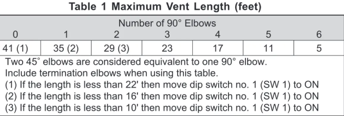
Ensure Rinnai approved venting materials are being used. Check that nothing is blocking the flue inlet or exhaust. Check all vent components for proper connections. Ensure vent length is within limits.
Ensure condensation collar was installed correctly. Verify dip switches are set properly.
Check fan for blockage.
Check that the gas is turned on at the water heater, gas meter, or cylinder. Ensure gas type and pressure is correct.
Ensure gas line, meter, and/or regulator is sized properly. Bleed all air from gas lines.
Verify dip switches are set properly. Ensure appliance is properly grounded. Disconnect all MSA controls.
Ensure igniter is operational.
Check igniter wiring harness for damage.
Check gas solenoid valves for open or short circuits.
Remove burner cover and ensure all burners are properly seated. Remove burner plate and inspect burner surface for condensation or debris.
Check that the gas is turned on at the water heater and gas meter. Check for obstructions in the flue outlet.
Ensure gas line, meter, and/or regulator is sized properly. Ensure gas type and pressure is correct.
Bleed all air from gas lines.
Ensure proper Rinnai venting material was installed. Ensure condensation collar was installed properly. Ensure vent length is within limits.
Verify dip switches are set properly. Ensure appliance is properly grounded. Disconnect keypad.
Disconnect all MSA controls if installed. Check power supply for loose connections.
Check power supply for proper voltage and voltage drops. Ensure flame rod wire is connected.
Check flame rod for carbon build-up.
Disconnect and re-connect all wiring harnesses on unit and PC board. Check all components for electrical short.
Check gas solenoid valves for open or short circuits.
Remove burner plate and inspect burner surface for condensation or debris.
Failure to remedy faults may result in severe burns, scalds, and/or death.
E R R O R M E S S A G E S
The Rinnai Water Heater has the ability to check its own operation continuously. If a fault
occurs, an Error Message will flash on the Digital Dispaly of the Remote Controller. This assists with diagnosing the fault, and may enable you to overcome a problem without a service call. Please identify the code displayed when inquiring about service.
Error 14 16 32 33 34 52 61 65 71 72 LC (00) No code Faulty Thermal Fuse
Over Temperature Warning
Outgoing Water
Temperature Sensor Fault Heat Exchanger Outgoing Temperature Sensor Fault Combustion Air Temperature Sensor Fault
Modulating Solenoid Valve Signal Abnormal
Combustion Fan Failure Water Flow Servo Faulty (Does not stop flow properly) SV0, SV1, SV2, and SV3 Solenoid Valve Circuit Fault Flame Sensing Device Fault
Scale Build-up in Heat Exchanger (when checking maintenance code history “00” is substituted for “LC” ) Nothing happens when water flow is activated.
Remedy
Check gas type of unit and ensure it matches gas type being used. Check for restrictions in air flow around unit and vent terminal. Check for low water flow in a circulating system causing short-cycling. Ensure dip switches are set to the proper position.
Check for foreign materials in combustion chamber and/or exhaust piping. Check heat exchanger for cracks and/or separations.
Check heat exchanger surface for hot spots which indicate blockage due to scale build up. Refer to instructions in manual for flushing heat exchanger.
Measure resistance of safety circuit.
Ensure high fire and low fire manifold pressure is correct. Check for improper conversion of product.
Check for restrictions in air flow around unit and vent terminal. Check for low water flow in a circulating system causing short-cycling. Check for foreign materials in combustion chamber and/or exhaust piping. Check for clogged heat exchanger.
Check sensor wiring for damage. Measure resistance of sensor. Clean sensor of scale build up. Replace sensor.
Check sensor wiring for damage. Measure resistance of sensor. Clean sensor of scale build up. Replace sensor.
Check for restrictions in air flow around unit and vent terminal. Check sensor wiring for damage.
Measure resistance of sensor. Clean sensor of scale build up.
Ensure fan blade is tight on motor shaft and is in good condition. Replace sensor.
Check modulating gas solenoid valve wiring harness for loose or damage terminals. Measure resistance of valve coil.
Ensure fan will turn freely.
Check wiring harness to motor for damaged and/or loose connections. Measure resistance of motor winding.
Water Flow Servo or wiring faulty. Check Water Flow Servo wiring harness connection. Measure resistance of Water Flow Servo wiring.
If blank screen is present on remote control then the Water Flow Servo has shorted out. Unplug Water Flow Servo. If remote lights up and unit starts operating then replace Water Flow Servo.
Check wiring harness to all solenoids for damage and/or loose connections. Measure resistance of each solenoid valve coil.
Ensure flame rod is touching flame when unit fires. Check all wiring to flame rod for damage.
Remove flame rod and check for carbon build-up; clean with sand paper. Check inside burner chamber for any foreign material blocking flame at flame rod. Measure micro amp output of sensor circuit with flame present.
Replace flame rod.
Flush heat exchanger. Refer to instructions in manual. Replace heat exchanger.
Clean inlet water supply filter.
On new installations ensure hot and cold water lines are not reversed.
Check for bleed over. Isolate unit from building by turning off hot water line to building. Isolate the circulating system if present. Open your pressure relief valve; if unit fires, there is bleed over in your plumbing.
Ensure you have at least the minimum flow rate required to fire unit. Ensure turbine spins freely.
Measure the resistance of the water flow control sensor.
Remote control does not light up but you have 12 VDC at the terminals for controls.
Always turn off the electrical power supply, the manual gas valve and the manual water control valve whenever servicing the unit.
M A I N T E N A N C E & S E R V I C E I N F O R M A T I O N
The Rinnai Water Heater should be checked by a Properly Trained Technician once a year. A Properly Trained Rinnai Technician should perform any repairs that may be necessary.
The following items should be checked each inspection:
1) The area around the Rinnai unit should be free from combustible materials such as cloth, vegetation and building materials. (see page 8)
2) Check burners for presence of foreign debris, insects or bugs. These items are not covered by the unit’s warranty.
3) Remove and clean the inlet water filter.
4) Keep the appliance area clear and free from combustible materials, gasoline, and other flammable vapors and liquids.
5) Do not obstruct flow of combustion and ventilation air.
In the case of any fault or error message from the Rinnai Water Heater, first turn all hot water taps off. Wait for 5 seconds. Turn the hot water tap back on. If the error message still remains, call your Rinnai Authorized Service Representative or Rinnai at 800-621-9419.
Should overheating occur or the gas supply fail to shutoff, turn off the manual gas control valve to the appliance.
DO NOT ATTEMPT TO SERVICE YOUR Rinnai YOURSELF. Call a Rinnai Authorized Service Technician or call your installer.
M A I N T E N A N C E & S E R V I C E I N F O R M A T I O N
MAINTENANCE SUGGESTIONS
This water heater has been designed and constructed for a long performance life when installed and operated properly under normal conditions. Regular inspections, as outlined in this section, are strongly recommended as a means of keeping your heater operating efficiently. Consideration should be given to periodic maintenance of scale removal in applications where the water
hardness quality is elevated and the water heater runs for extended periods such as in commercial applications or applications with circulating loops.
1. Cleaning
The water heater should be cleaned annually. Keep the water heater clear of dust and debris especially in and around burner.
Cleaning procedures for the Rinnai Water Heater are as follows:
1) Turn off and disconnect electrical power. Allow to cool for one hour.
2) Remove the Front Panel by removing screws. See parts breakdown on panels.
3) Use pressurized air to remove dust from around main burner.
4) Use soft dry cloth to wipe cabinet.
DO NOT DAMAGE OR DISTORT ANY PARTS
OF HEATER.
DO NOT USE WET CLOTH OR SPRAY
CLEANERS ON BURNER.
2. Visual check of main burner flames.
The burner must flame evenly over the entire surface when operating correctly. The flame must burn with a clear, blue, stable flame. See the parts breakdown of the burner for the location of view ports. Any and all parts removed for inspection or service must be replaced before operating the unit. The flame pattern should be as shown in the
* VENT MAINTENANCE
* VENT SYSTEM
Must be checked annually for blockage or deterioration. See vent installation instructions.
* MAINTENANCE-ELECTRIC
MOTORS
Motors are permanently lubricated and need no
lubrication. Keep fan and motor free of dust and dirt, clean annually.
If you do not follow these instructions exactly, a fire or explosion may result causing property damage, personal injury or loss of life.
TROUBLE SHOOTING AND COMMON QUESTIONS
Q
- I don't have any hot water when I open the tap!A
- Make sure there is gas, water and electricity to the Rinnai Water Heater (the power is turned on and the gas is turned on)Q
- When I was using the hot water, the water got cold!A
- If you adjusted the flow from the tap to lessen it, you may have gone below the minimum flow required. The Rinnai Water Heater requires a minimum flow rate to operate (see specification page for flow rate of your unit). If you mix the water with a tap and attempt to get a temperature well below the temperature being controlled by the unit, it may drop the flow below the desired minimum flow rate. Decrease the temperature supplied by the Rinnai Water Heater at the remote control or increase your total flow.Q
- White smoke comes out of the exhaust!A
- During colder weather when the exhaust temperature is hotter than the air, the exhaust fumes condense producing white steam.Q
- When I open a hot tap. I do not immediately get hot water!A
- Hot water must travel through your plumbing from the Rinnai Water Heater to the faucet. The time period for hot water to reach your fixture is determined by the amount of water in your plumbing system between your water heater and the fixture, water pressure, flow rate of fixture in use, etc.Q
- After I turn off the hot water tap, the fan on the Rinnai Water Heaters continues to run!A
- The fan is designed to be on for 65 seconds after the flow of water stops.This is to ensure constant water temperatures during rapid starting and stopping, as well as exhausting any residual gas flue products from the unit.FOR YOUR SAFETY READ BEFORE OPERATING
A. This appliance does not have a pilot. It is equipped with a direct ignition device which automatically lights the burner. Do not try to light the burner by hand.
B. BEFORE OPERATING: Smell all around the appliance area for gas. Be sure to smell next to the floor because some gas is heavier than air and will settle on the floor.
WHAT TO DO IF YOU SMELL GAS
•
Do not try to light any appliance.•
Do not touch any electric switch, do not use any phone in your building.•
Immediately call your gas supplier from aneighbor’s phone. Follow the gas supplier’s instructions.
•
If you cannot reach your gas supplier, call the fire department.C. Use only your hand to operate remote control keypad. Never use tools. If the remote
keypad doesn’t work, do not try to repair it, call a qualified service technician. Force or attempted repair may result in a fire or explosion.
D. Do not use this appliance if any part has been under water. Immediately call a qualified service technician to inspect the appliance and to replace any part of the control system and any gas control which has been under water.
ßClosed manual valve (“OFF” position)
Open Manual valve (“ON” position)®
To Turn Off Gas To Appliance
1) Set the thermostat to lowest setting.
2) Turn off all electric power to the appliance if service is to be performed. 3) Turn the manual valve at gas inlet of appliance clockwise to “OFF”
O P E R A T I N G I N S T R U C T I O N S
inlet of appliance counterclockwise to “ON”.
8) Turn on all electric power to the appliance.
9) Set thermostat to desired setting. 10) If the appliance will not operate,
Follow the instructions “To Turn Off Gas To Appliance” and call your service technician or gas supplier. 1) STOP! Read the safety information above
before proceeding.
2) Set the thermostat to lowest setting.3) Turn off all electric power to the appliance. 4) This appliance does not have a pilot. It is
equipped with a direct ignition device which automatically lights the burner. Do not try to light the burner by hand.
5) Turn the manual valve located at gas inlet of the appliance clockwise to “OFF”.
6) Wait 5 minutes to clear out any gas. If you then smell gas, STOP! Follow “B” in the safety information above on this label. If you don’t smell gas, go to next step. 7) Turn the manual valve located at the gas
C A R E & L I M E C O N D I T I O N W A R N I N G
Care of Unit’s Exterior:
Keep the exterior cabinet clean. Use a soft cloth and warm water when cleaning the cabinet. Do Not use volatile substances such as benzene and thinners, as they may ignite, or cause fading of the paint.
Lime Condition Warning Signal:
If you notice “LC” flashing on the remote key pad, this means the unit is beginning to lime up, and MUST be flushed. Contact a qualified Rinnai service technician to flush the appliance. Failure to flush the appliance when “LC” is flashing, will cause damage to the heat exchanger. Damage caused by lime build up is not covered by the unit’s warranty. To reset the LC Fault Code, turn the power off to the unit. Once power is restored, the LC code will be reset.
Water Quality:
Consideration of care for your water heater should include evaluation of water quality. If the water quality exceeds the target levels provided in the table, you may want to treat or condition the water.
Description pH Dissolved Solids)TDS (Total HardnessTotal Aluminum Chlorides Copper Iron Manganese Zinc
Installer’s Instructions
This section is for the Qualified Installer
only.
If you are not properly trained,
you should not install this unit.
The
warranty may be voided due to installation
by a non-qualified installer. For information
on Rinnai Training Courses, call
1-800-621-9419.
www.rinnai.us 800-621-9419
Warnings ... 26,27 Locating the Vent Terminal ... 28 Performance Data ... 29 Dimensions ... 30 Recommended Piping for Installation ... 31,32,33,34 Venting ... 35,36 Freeze Protection ... 37 Gas Piping Sizing Chart ... 38 Gas Piping Notes ... 39 Water Piping Notes... 40 Pressure Relief Valve ... 40 Lighting the Unit ... 41 Remote Controllers ... 42 Remote Controllers Installation ... 43,44 Testing ... 45 Schematic Diagram ... 46,47
Contents
of Installer’s
This manual must be followed exactly.
1) Read the safety issues completely before installing the Rinnai Water Heater. 2) This water heater is suitable for residential water (potable) heating ONLY.
DO NOT use this water heater for space heating, combination space heating/ domestic water heating, or commercial water heating applications.
3) The Rinnai Water Heater is not suitable for use in pool or spa applications. 4) This unit is designed to be installed indoors using the proper vent piping to
exhaust by-products of combustion to the outside environment. Contact your dealer or Rinnai for proper vent kits. DO NOT operate this unit without vent piping connected. Exhaust gasses must be expelled outside the home. 5) Maintain proper space around the unit for proper servicing and operation.
Minimum clearances from combustible materials are listed below. Top of Heater 6 inches
Back of Heater 0 inch Front of Heater 6 inches Sides of Heater 2 inches
Floor 12 inches
Vent/Air Intake 0 inches
6) Installer must install a Pressure relief valve. Pipe pressure relief discharge to a drain or outside environment (See pressure relief valve section).
7) The appliance should be located in an area where leakage of the unit or connections will not result in damage to the area adjacent to the appliance or to lower floors of the structure. When such locations cannot be avoided, it is recommended that a suitable drain pan, adequately drained, be installed under the appliance. The pan must not restrict combustion air flow.
I N S TA L L E R ’ S I N S TA L L AT I O N I N S T R U C T I O N S
-Warnings- (Residential Unit)
This manual must be followed exactly.
1) Read the safety issues completely before installing the Rinnai Water Heater. 2) This water heater is suitable for water (potable) heating or space heating.
- The piping and components connected to the Rinnai Water Heater must approved for use in portable water systems.
- Toxic chemicals such as those used for boiler water treatment are NOT to be introduced to the portable water used for space heating.
- The Rinnai Water Heater, if it will be used as a potable water source, must not be connected to a system that was previously used with a nonpotable
water heating appliance.
- When the system requires water for space heating at temperatures higher than required for other uses, a means such as mixing valve shall be installed to temper the water for other uses in order to reduce the scald hazard potential. 3) The Rinnai Water Heater is not suitable for use in pool or spa applications 4) This unit is designed to be installed indoors using the proper vent piping to
exhaust by-products of combustion to the outside environment. Contact your
dealer or Rinnai for proper vent kits. DO NOT operate this unit without vent piping connected. Exhaust gasses must be expelled outside the home.
5) Maintain proper space around the unit for proper servicing and operation. Minimum clearances from combustible materials are listed below.
Top of Heater 6 inches
Back of Heater 0 inch
Front of Heater 6 inches
Sides of Heater 2 inches
Floor 12 inches
Vent/Air Intake 0 inches
I N S TA L L E R ’ S I N S TA L L AT I O N I N S T R U C T I O N S
-Warnings- (Commercial Unit)
6) Installer must install a Pressure relief valve. Pipe pressure relief discharge to a drain or outside environment (See pressure relief valve section).
7) The appliance should be located in an area where leakage of the unit or connections will not result in damage to the area adjacent to the appliance or to lower floors of the structure. When such locations cannot be avoided, it is recommended that a suitable drain pan, adequately drained, be installed under the appliance.
NOTE: PLEASE CONSULT WITH LOCAL CODES BEFORE INSTALLING THIS UNIT
NOTE: ONLY Rinnai Approved vent materials and components can be used to vent the water heaters. When installing your Rinnai vent system, you MUST follow Rinnai’s Venting Instructions found in each vent terminal box. These instructions provide the maximum allowable vent heights for both horizontal and vertical venting, how to cut the vent components, and pipe installations.
s n o i t a ll a t s n I . S . U N O I T P I R C S E D F E R CanadianInstallations y n o c l a b r o , k c e d , h c r o p , a d n a r e v , e d a r g e v o b a e c n a r a e l C A 1foot 1foot d e n e p o e b y a m t a h t r o o d r o w o d n i w o t e c n a r a e l C B 1foot 3feet w o d n i w d e s o l c y l t n e n a m r e p o t e c n a r a e l C C * * * * * * * * * * g n a h r e v o r o s e v a e , t i f f o s d e t a li t n e v o t e c n a r a e l c l a c i t r e V D g n a h r e v o r o s e v a e , t i f f o s d e t a li t n e v n u o t e c n a r a e l C E r e n r o c e d i s t u o o t e c n a r a e l C F r e n r o c e d i s n i o t e c n a r a e l C G H aCslesearmanblcyetoeachsideofcenter ilneextendedabovemeter/regulator * t h 5 1 g i e h a n i h t i w t e e f 3 e h t e v o b a t e e f y l b m e s s ater/regulator e m * t e l t u o t n e v r o t a l u g e r e c i v r e s o t e c n a r a e l C I 3feet J cColemabraunstcieontoainroinnlmetetcohaanniycoatlhaeirrsauppppillaynicnelettobulidingorthe 1foot 3feet t e e f 6 3 feet above if within
10 feet horizontally g n i d li u b a o t n i t e l n i r i a d e c r o f a o t e c n a r a e l C K L p oCr p tleae yrarnceabovepavedsidewalkorpaveddrivewaylocatedonpubilc * 7feet * 1foot ) s e d i s 3 n o n e p o ( y n o c l a b r o , h c r o p , a d n a r e v , k c e d r e d n u e c n a r a e l C M e s u , 9 4 1 B -A G C / N A C r o 4 5 A P F N / 1 . 3 2 2 Z I S N A n i d e i f i c e p s t o n s e c n a r a e l c r o F * clearancesinaccordancewithlocal . r e i l p p u s s a g e h t f o t n e m e r i u q e r e h t d n a s e d o c n o i t a l l a t s n i
NOTE: Maintain 12” of clearance above the highest anticipated snow level or grade, or whichever is greater. Please refer to your local codes for the snow level in your area.
I N S TA L L E R ’ S I N S TA L L AT I O N I N S T R U C T I O N S
Locating the vent terminalTerminals should be so positioned as to avoid products of combustion entering openings into buildings or other flues or vents.
0 . 0 0 . 5 0 . 0 1 0 . 5 1 0 . 0 2 0 . 5 2 0 . 0 3 9 8 7 6 5 4 3 2 1 0 ) m p g ( w o l F r e t a W P re s s u re L o s s ( p s i) 0 . 0 0 . 0 1 0 . 0 2 0 . 0 3 0 . 0 4 0 . 0 5 0 . 0 6 P re s s u re L o s s ( ft h e a d ) V2532FFU/FFUC V2532FFUD/FFUCD V2520FFU/FFUC V2520FFUD/FFUCD 0 . 0 0 . 1 0 . 2 0 . 3 0 . 4 0 . 5 0 . 6 0 . 7 0 . 8 0 . 9 0 5 1 5 2 1 0 0 1 5 7 0 5 5 2 0 H ot W at er F lo w R at e (g pm ) V2520FFU/FFUC V2520FFUD/FFUCD V2532FFU/FFUC V2532FFUD/FFUCD
I N S TA L L E R ’ S I N S TA L L AT I O N I N S T R U C T I O N S
PRESSURE DROP CURVEI N S TA L L E R ’ S I N S TA L L AT I O N I N S T R U C T I O N S
OUTLET FLOW DATA8” 7/8” 4-1/8” 3/4” 5” 4-3/4” 3/4” 3-1/2” 4-3/4” BC-100V-1US FITTING DIAMETER MC-100V-1US MC-91-1US C B A G F D I K E H J C B A G F J D I E H K
DIM DESCRIPTION REU-V2532FFUCREU-V2532FFU REU-V2520FFUCREU-V2520FFU
A Width B Depth C Height - Unit
D Height - Including Brackets E Hot Water Outlet (from wall) F Hot Water Outlet (from center) G Cold Water Outlet (from wall) H Cold Water Outlet (from center)
I Gas Connection (from wall)
J Gas Connection (from center)
Gas: Length to Connection (from base) Cold: Length to Connection (from base) Hot: Length to Connection (from base) Gas: Fitting Diameter
13.8" 9.2" - 10.8" 23.6" 24.7" 3.6" - 5.1" 4.3" 2.8" - 4.3" 1" 3.9" - 5.5" 3.5" 1.6" 2" 1.6" 3/4"NPT K REU-V2532FFUD
REU-V2532FFUCD REU-V2520FFUCDREU-V2520FFUD
14.0" 9.6" - 11.2" 22.9" 25.6" 3.6" - 5.1" 4.3" 2.8" - 4.3" 1" 3.9" - 5.5" 3.5" 1.6" 2" 1.6" 3/4"NPT
INSTALLER’S INSTALLATION INSTRUCTIONS
DimensionsGas Supply 3/4" Cold Water Supply Line 3/4" Hot Water Supply Line
Rinnai Water Heater Rinnai Equipment List (Residential and Commercial) Rinnai Water Heaters (Indoor) MC-91 Controller (Included) MC-100V and BC-100V Controllers Optional RIK-KIT (Optional) (3/4" Fittings Include: 2 Unions, 2 Ball Valves, 2 Drain Valves and 1 Pressure Relief Valve.)
QTY
1 1
1
3/4" Gas Connection
Venting Equipment List Indoor Unit
Please Review Venting Instructions/Guidelines for Proper Components and Installation.
For Building Fixtures
103 International Drive
Peachtree City, Georgia 30269
RINNAI WATER HEATERS
Domestic Hot Water - Standard Installation 1 Rinnai Water Heater
This is not an engineered drawing, it is intended only as a guide and not as a replacement for professionally engineered project drawings. This drawing is not intended to describe a complete system, it is up to the contractor/engineer to determine the necessary components for and configuration of the particular system being installed. The drawing does not imply compliance with local building code requirements. It is the engineer/contractor responsiblity to ensure the installation is in accordance with all local building codes. Confer with local building officials before installation.
Pressure Relief Valve 3/4" Ball Valve 3/4" Union Check Valve S Pressure Regulator Circulating Pump Solenoid Valve Boiler Drain Valve
KEY (Residential and Commercial)
I N S TA L L E R ’ S I N S TA L L AT I O N I N S T R U C T I O N S
RECOMMENDED PIPING FOR BASIC INSTALLATION103 International Drive
RINNAI WATER HEATERS
Domestic Hot Water - Circulation Systems 1 Rinnai Water Heater with Electric Storage Tank
This is not an engineered drawing, it is intended only as a guide and not as a replacement for professionally engineered project drawings. This drawing is not intended to describe a complete system, it is up to the contractor/engineer to determine the necessary components for and configuration of the particular system being installed. The drawing does not imply compliance with local building code requirements. It is the engineer/contractor responsiblity to ensure the installation is in accordance with all local building codes. Confer with local building officials before installation.
Pressure Relief Valve 3/4" Ball Valve 3/4" Union Check Valve S Pressure Regulator Circulating Pump Solenoid Valve Boiler Drain Valve
KEY
Minimum 3/4" Cold Water Supply Line
2-5 Gallon Electric Water
Heater
120°F Building Fixtures
Building Return (Not required to be 3/4" Line) Building Supply Expansion Tank Gas Supply QTY 1 1 1 Rinnai Water Heater
Pump Should be Controlled by an Aquastat, Timer or Combination Aquastat and Timer. Pump to be sized for Pressure Drop through Building Supply and Return Piping. Pump to be of Bronze or Stainless Construction. Notes:
PLEASE NOTE FOR RESIDENTIAL APPLICATIONS, THIS PIPING ARRANGEMENT MAINTAINS FULL WARRANTY:
10 Years On Heat Exchanger 5 Years On Parts
Commercial Application Warranty: 5 Years On Heat Exchanger
5 Years On Parts Rinnai Equipment List (Residential and Commercial) Rinnai Water Heaters (Indoor) MC-91 Controller (Included) MC-100V and BC-100V Controllers Optional RIK-KIT (Optional) (3/4" Fittings Include: 2 Unions, 2 Ball Valves, 2 Drain Valves and 1 Pressure Relief Valve.) 3/4" Gas Connection
Important: Install building return line to the hot supply as close as possible to the Rinnai Water Heater.
Venting Equipment List (Commercial and Residential) Indoor Unit
Please Review Venting Instructions/Guidelines for Proper Components and Installation.
I N S TA L L E R ’ S I N S TA L L AT I O N I N S T R U C T I O N S
RECOMMENDED PIPING FOR CIRCULATION SYSTEMS103 International Drive
Peachtree City, Georgia 30269
RINNAI WATER HEATERS Domestic Hot Water with Circulation
1 Rinnai Water Heater
This is not an engineered drawing, it is intended only as a guide and not as a replacement for professionally engineered project drawings. This drawing is not intended to describe a complete system, it is up to the contractor/engineer to determine the necessary components for and configuration of the particular system being installed. The drawing does not imply compliance with local building code requirements. It is the engineer/contractor responsiblity to ensure the installation is in accordance with all local building codes. Confer with local building officials before installation.
Pressure Relief Valve 3/4" Ball Valve 3/4" Union Check Valve S Pressure Regulator Circulating Pump Solenoid Valve Boiler Drain Valve
KEY
Minimum 3/4" Hot Water Supply Line
Building Fixture Outlets
(Optional) 2-6 Gallon Storage Tank
(To eliminate cold water sandwich effect caused by frequent On/Off operation)
Pump Should be Controlled by an Aquastat, Timer or Combination
Aquastat and Timer
Pump to be sized for 3.0 gpm flow @ 12 feet head. Flow Balancing Valve to be adjusted to 3 GPM flow through water heater with no hot water taps open. Pump to be of Bronze or Stainless Construction.
Cold Water Supply and Circulation Return Lines Must Be 3/4" Tubing Throughout Circulation Loop.
Note:
Water heater outlet temperature cannot be adjusted when circulation pump is running.
QTY 1 1 1 Expansion Tank Rinnai Water Heater Note:
PLEASE NOTE FOR RESIDENTIAL APPLICATIONS, THIS PIPING ARRANGEMENT REDUCES WARRANTY TO THE FOLLOWING: 3 Years On Heat Exchanger
3 Years On Parts Rinnai Equipment List (Residential and Commercial) Rinnai Water Heaters (Indoor) MC-91 Controller (Included) MC-100V and BC-100V Controllers Optional RIK-KIT (Optional) (3/4" Fittings Include: 2 Unions, 2 Ball Valves, 2 Drain Valves and 1 Pressure Relief Valve.) 3/4" Gas Connection
Commercial Application Warranty: 5 Years On Heat Exchanger 5 Years On Parts
Gas Supply
Venting Equipment List (Residential and Indoor Unit
Please Review Venting Instructions/Guidelines for Proper Components and Installation.
Commercial)