High-strength large-diameter pipe for
long-distance high pressure gas pipelines
M. K. Gräf
Europipe GmbH
H.-G. Hillenbrand
Europipe GmbH
C. J. Heckmann
Mannesmann Forschungsinstitut GmbH
K. A. Niederhoff
Mannesmann Forschungsinstitut GmbH
ISOPE 2003
High-strength large-diameter pipe for long-distance high pressure gas pipelines
M. K. Gräf1, H.-G. Hillenbrand2, C. J. Heckmann3, K. A. Niederhoff3
1
Europipe GmbH 2Europipe GmbH 3Mannesmann Forschungsinstitut
Mülheim, Germany Ratingen, Germany Duisburg, Germany
ABSTRACT
The ever-increasing demand for natural gas will further influence the type of its transportation in the future, both from the strategic and economic point of view. Long-distance pipelines are a safe and economic means to transport the gas from production sites to end users. The energy scenario has been changing quickly in recent years. International studies forecast that the demand for natural gas will be nearly doubled by 2030. The distance between gas production sites and end users increases, implying the need for the construction of complex gas transportation pipeline networks, when the use of LNG tankers is impossible or uneconomical. This will make the high pressure natural gas transportation via pipelines increasingly interesting.
The use of grade X 80 linepipe has already been shown to result in substantial cost savings. Results of tests on grade X 80 production pipe supplied for onshore and offshore projects are presented in this paper. But the economic transport of gas over very long distances requires additional cost cuts. The use of grade X100 and/or X120 could be a solution. Therefore, the benefits of using high-strength linepipe and the present-day technical limitations on its production are addressed. Laboratory and production results on high-strength large-diameter pipes are presented to describe the materials properties as well as the service behaviour. Girth welding procedures covering mechanised and manual methods have already been developed.
INTRODUCTION
This paper gives an overview of the development of high-strength low-alloy linepipe grades. Some of the current projects for pipelines in grade X 80 and the benefits of using X 80 pipe are presented. Also, important aspects of the properties of base material and welds are discussed. The development of material grades up to X 100 or X 120 represents one of the big challenges and opportunities in the future. Special attention is focused on the effect of boron on the mechanical properties of the material grades between >X 80 and X 120. Furthermore, the various aspects of production welds and field weldability are dealt with.
PROJECT COST REDUCTION
Project cost reduction may be a result of the sum of the different benefits that can be derived by using high-strength steels /1/, even when the price per tonne of the pipe increases as the material grade increases. The benefits include:
• reduced quantity of steel required
• lower pipe transportation costs
• lower pipelaying costs.
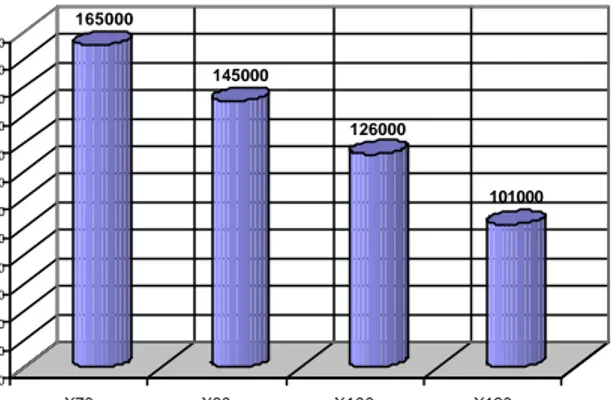
The use of grade X 80 linepipe in the construction of the first Ruhrgas X80 pipeline led to a material saving of about 20 000 t, compared with grade X 70 pipes (Figure 1), through a reduction of the wall thickness from 20.8 mm for X 70 to 18.3 mm for X 80. This resulted also in a reduction of the pipelaying costs because of reduced pipe transportation costs and greatly reduced welding costs through reduced welding times needed with thinner walls. The use of materials with still higher strength, such as grade X 100 or grade X 120 could lead to further material savings as it is further illustrated in Figure 1.
165000 145000 126000 101000 50000 60000 70000 80000 90000 100000 110000 120000 130000 140000 150000 160000 170000
Pipe line weight [t]
X70 X80 X100 X120
API steel grade
Figure 1: Possible material savings through the use of high strength material
A preliminary economic evaluation /2/ highlighted that high pressure X 100 pipelines could give investment cost savings of about 7% compared with grade X 80 pipeline. This study claims cost savings of up to 30 % when X 70 and X 100 are compared. Given that, in a complex pipeline network operating at high pressure, the capital expenditure is very high, it becomes understandable how much more attractive the high strength steel option could be.
On the other hand, it becomes clear from Figure 2 that the reduction in the manufacturing cost per tonne of the pipe at a given transport capacity of a pipeline is enhanced not just by the increase in the material grade of the steel but also by the reduction in pipe wall thickness. From the point of view of pipe manufacturers, reduction of pipe wall thickness is not a preferred option. A reduction in pipe diameter at constant pipe thickness and a simultaneous increase in pipeline operating pressure would represent, in our opinion, a more favourable solution to the problem.
450 550 650 750 850 950 1050 1150 1250 X60 X80 X100 X120
API steel grade
Manufacturing cost per metric tonne
19.1 mm 25.4 mm 12.7 mm
15.9 mm
Figure 2: Manufacturing cost per tonne of pipe for different steel grades and wall thicknesses to be used at a constant transportation capacity
DEVELOPMENT OF HIGH-STRENGTH STEEL GRADES The improved processing method for currently used high-strength steels like X 80 and higher, consists of thermomechanical rolling (emerged in the 1980s) followed by accelerated cooling. By this method, it has become possible to produce high-strength NbTi microalloyed material, having a reduced carbon content and thereby excellent field weldability. Additions of molybdenum, copper and nickel enable the strength level to be raised to that of grade X 100, when the steel is processed to plate by thermomechanical rolling plus modified accelerated cooling. The development of high strength steel for pipes in grade X 120 consists of further optimisation of the thermomechanical treatment and the use of niobium, titanium and boron as microalloying elements. First results of this development as regards the mechanical properties of the new material are very encouraging.
GRADE X 80
X 80 Projects and relevant pipe properties
In the past two decades, EUROPIPE has carried out extensive work to develop high-strength steels in grades X 80 and X 100 to assist customers in their endeavour to reduce pipe weight and pipelaying costs.
Since 1984 longitudinal seam submerged-arc welded grade X 80 pipe has been used in the implementation of several pipeline projects in Europe and North America (Figure 3). In 1984, EUROPIPE produced the grade X 80 linepipe installed, for the first time in history, in the Megal II pipeline. A manganese-niobium-titanium steel, additionally alloyed with copper and nickel, was used for the production of the 44” OD x 13.6 mm WT pipe. Subsequent optimisation of the production parameters enabled the CSSR order to be executed using a manganese-niobium-titanium steel without the additions of copper and nickel.
YEAR ORDER PIPE GEOMETRY PIPELINE LENGTH
1984 Megal II 44" x 13.6 mm 3.2 km
1985 CSSR 56" x 15.5 mm 1.5 km
1991/92 Ruhrgas 48" x 18.3 mm 250 km
2001-03 CNRL 24" x 25.4 mm 12.7 km
2001-03 Transco 48" x 14.3/15.1 mm 158 km +
Figure 3: Europipe Projects executed with linepipes made of grade X80
The first pipeline using GRS 550 (X 80) for its entire length of 250 km was the Ruhrgas Werne-to-Schlüchtern pipeline project implemented in Germany in 1992. EUROPIPE supplied all 48” diameter pipe with up to 19.3 mm wall thickness and the necessary induction bends. Since the strength decreases as the wall thickness increases, it had been necessary at that time to raise the carbon and manganese levels marginally. The concentrations of all other elements remained unchanged.
The measured tensile strength and impact energy values conformed fully to the specification requirements in all cases. The standard deviation for the yield and tensile strength values was very low. The impact energy values measured on Charpy V-notch impact specimens at 0°C was very high, averaging to about 180 J. The 85% shear area transition temperatures determined in the drop weight tear (DWT) tests were far below 0°C.
In 2001, 2002 and 2003, X 80 (L555MB) pipes were manufactured again for Transco projects in the UK. Linepipe for several parts of gas pipeline networks of about 158 km length in total was produced. EUROPIPE supplied pipe of 48” diameter with the thicknesses of 14.3 mm and 15.1 mm. Another 52 km are ordered for 2004.
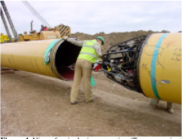
Figure 4 shows a view of the Transco pipeline construction site. After finishing welding, non destructive examination and field joint coating, the girth welded pipeline sections were lowered onto the prepared trench bottom.
The results of the tests performed by EUROPIPE on production pipe in the context of certification of the pipe are shown in Figures 5 and 6. All results of the tensile and impact tests performed were within the specification for grade X 80. The standard deviation was 15 MPa for the yield strength values and 13 MPa for the tensile strength values. The average value of impact energy was 227 J for base metal and 134 J for weld metal.
Figure 4: View of a pipelaying operation (Transco project)
Figure 5: Tensile properties of Transco grade X 80 pipe (48” OD x 15.1 mm WT)
Figure 6: Toughness properties of Transco grade X 80 pip e (48”OD x 15.1 mm WT)
One of the most challenging projects encountered in 2001 was a hot steam system for CNRL in Canada /3/. The longitudinally welded linepipe was qualified for use at temperatures up to 354°C. The high temperature properties were determined and found satisfactory. For a new hot steam pipeline section, further 7.7 km of pipe have been ordered recently.
To demonstrate the manufacturability of heavy wall grade X 80 pipe, EUROPIPE produced for the design of containment cylinders for PNG
tankers, X 80 linepipe material with 33 mm wall thickness. Figures 7 and 8 give an idea of the installation of such a PNG tanker. About 40.000 tonnes of gas can be shipped per vessel and there is no need to treat or cool the gas. An approval of this concept was given by DNV.
Figure 7: Design of containment cylinders for PNG tankers
Figure 8: Design of a PNG tanker
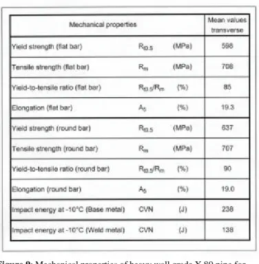
The mechanical properties of the X 80 pipes used for the cylinders are summarised in Figure 9. All values of the tensile and impact tests met the requirements. The Charpy V-notch impact energy measured at -10°C was in excess of 200 J. Because this is not an application under arctic conditions, neither a high toughness at low temperatures nor BDWT tests are required. The pipe forming and welding operations did not cause any problems.
Field welding of grade X 80 pipe
Pipeline construction needs welding operations by manual SMAW and automatic GMAW. These welding methods are well-established now and regarded as sufficiently validated for large-scale use /4-6/.
Besides manual SMAW, automatic GMAW became increasingly important as an economic process because of a reduced welding time required with narrow gaps. Narrow gaps require a reduced number of individual passes. One of the very efficient automatic GMA welding processes used is the CRC process that was also partly used for the construction of the Werne–to–Schlüchtern pipeline and the recent Transco projects. Figure 10 describes a welding procedure applied to X 80 pipes. Figure 11 shows the mechanical properties and the toughness of the girth welds, which conform to typical specification requirements comfortably.
Design pressure, 250 bar Incidental pressure, 262.5 bar Height: appr. 36 meter I.D.: 1000 mm Volumes:
Weight of each cylinder: appr. 31 Mt No. of cylinders: 3600
Total weight of cylinders: 112.000 Mt Design premises:
X80 line pipe material 33 mm WT.
Figure 9: Mechanical properties of heavy wall grade X 80 pipe for PNG containment cylinders
Figure 10: Typical welding parameters for GMAW of grade X 80 by the CRC process CVN Toughness 300 270 240 210 180 150 120 90 60 30 0 800 700 600 500 400 300 200 100 0 Strength [MPa] Strength Properties
( Flat Specimen crossweld ) Fracture Toughness
WM -30°C WM 0°C HAZ 0°C 550 690 YS TS
Figure 11: Test results on X 80 girth welds (CRC process)
DEVELOMENT OF GRADE X100/X120
To cope with the market requirements for enhanced pipe strength, EUROPIPE put its effort to the development of grade X 100. No technological breakthroughs in TM rolling and accelerated cooling had been necessary. Only optimisation of the existing technology was required for the production of grade X 100 plate. As a result, the production window became narrower. Heat treatment of plate or pipe was obviously not necessary.
Since 1995, EUROPIPE has developed different approaches to produce high strength materials /1/. As can be seen in Figure 12, three different approaches are generally possible in selecting the chemical composition and plate rolling conditions.
Figure 12: Different approaches to reach the strength level of grade X 100 by varying the steel chemistry as well as the cooling parameters during plate manufacture /7/
Approach A (Table 1), which employs a relatively high carbon equivalent, at 0.49, has the disadvantage that the crack arrest toughness properties are not good and therefore requirements to prevent long-running cracks may not be fulfilled. Moreover, this approach is also detrimental, e.g. to field weldability. A typical result of this approach was follows:
Table 1: Approach A for the production of plate in API grade X100
Approach B (Table 2), which adopts a carbon equivalent of only 0.43 and which is used in combination with fast cooling rates in the plate mill down to a very low cooling-stop temperature, results in the formation of large fractions of martensite in the microstructure, which
Pass Consumables Current
[A] Voltage [V] Root Pass Hot Pass Filler Passes Cap Pass Thyssen K Nova Thyssen NiMo 80 0.9 0.9 0.9 0.9
Trade name[mm]dia.
190/220 240/260 200-230 19/21 24/26 22/25 20/22 Thyssen NiMo 80 Thyssen NiMo 80 Shielding Gas Thyssen K Nova Ar/CO2 75/25 Ar/CO2 75/25 CO2 CO2 210/250 Welding speed [cm/min] Oscil -lation 75 127 36/45 26/41 n n y y
Heat pipe size
OD X WT C M n Si M o Ni Cu N b T i N CEIIW PCM I 30" x 19.1 mm 0 . 0 8 1.95 0.26 0.26 0.23 0.22 0.05 0.018 0.003 0 . 4 9 0.22 Approach A Heat I CVN (20°C) DWTT-transition temperature 739 MPa 792 MPa 0.93 18.4% 235 - 15 °C
* transverse tensile tests by round bar specimens yield strength Rt0.5 * tensile strength Rm * yield t o tensile ratio Rt0.5 / Rm * Elongation A5 *
has a detrimental effect on the toughness properties of base metal. This effect cannot be adequately compensated for by using extremely low carbon contents.
In addition, softening of the heat affected zone was observed.
Table 2: Approach B for the production of plate in API grade X100
Experience gained meanwhile indicates that Approach C (Table 3) is the best choice. This approach enables the desired property profile to be achieved through an optimised two-stage rolling process in conjunction with a medium carbon content, a medium carbon equivalent and an optimised cooling process. The special potential of the existing rolling and cooling facilities contributes significantly to the success of this approach.
The medium carbon content employed in Approach C ensures excellent toughness as well as fully satisfactory field weldability, despite the relatively high carbon equivalent, at about 0.46. The chemical composition should therefore be considered acceptable for the purpose of current standardisation.
EUROPIPE has already produced hundreds of tonnes of grade X 100 pipe adopting Approach C. Recent trials have covered the wall thickness range between 12.7 and 25.4 mm. It was demonstrated that the same steel composition could be used and only slight changes in the rolling conditions would be necessary.
Table 3: Approach C for the production of plate in API grade X100
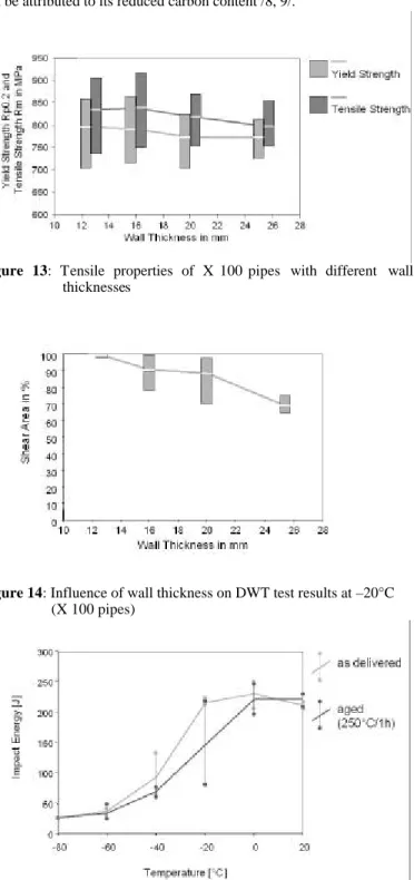
As can be seen in Figure 13, the results on production pipes show uniform strength properties for all the wall thicknesses tested. Tensile tests were performed using round bar specimens. Yield-to-tensile ratios were still relatively high. The elongation values are lower than those known for grade X 70. The impact energy (CVN) measured was in
excess of 200 J in all cases. It seems to be impossible to guarantee values in excess of 300 J at low temperatures on a production basis. In
Figure 14, the DWT test results at –20°C are shown for the different wall thicknesses. Typically, the shear area values are higher for thin-wall X 100 material. Because of the relatively high carbon equivalent and the high strength level, the toughness of the longitudinal seam weld metal and the HAZ is limited. The X 100 material produced responds favourably to manual and mechanized field welding, a finding which can be attributed to its reduced carbon content /8, 9/.
Figure 13: Tensile properties of X 100 pipes with different wall thicknesses
Figure 14: Influence of wall thickness on DWT test results at –20°C (X 100 pipes)
Figure 15: Charpy test results on 36” OD x 16 mm WT grade X 100 pipe in the as delivered and aged conditions
H e a t pipe size O D X W T C M n Si M o N i Cu Nb Ti N C EIIW PC M II Approach B H e a t II C V N ( 2 0 ° C ) D W T T -transition temperature 7 5 5 M P a 820 MPa 0 . 9 2 17.1 % 240 - 25 °C 3 0 " x 1 5 . 9 m m 0 . 0 7 1.89 0.28 0.15 0.16 - 0.05 0.015 0.004 0.43 0.19 yield strength Rt0.5 * tensile strength Rm * yield to tensile ratio Rt0.5 / Rm * E l o n g a t i o n A5 *
Heat pipe size
O D X W T C M n S i M o Ni C u Nb T i N C EIIW PCM III Heat III yield strength Rt0.5 * tensile strength Rm * yield to tensile ratio Rt0.5 / Rm * Elongation A5 * CVN (20°C) DWTT-transition temperature 737 MPa 800 MPa 0.92 18 % 200 J - 20 °C 56" x 19.1 mm 0.07 1.90 0.30 0.17 0.33 0.20 0.05 0.0180.005 0.46 0.20 IV 36" x 16.0 mm 0.06 1.90 0.35 0.28 0.25 - 0.05 0.0180.004 0.46 0.19 IV 752 MPa 816 MPa 0.92 18 % 270 J ∼ - 50 °C 200-270 J
* transverse tensile tests by round bar specimens ** -60°C for WT 12.7mm -10°C for WT 25mm
For reasons of technical feasibility and cost-effective production, it is necessary in the context of grade X 100 to reassess and redefine some of the requirements for mechanical properties, giving consideration to anticipated service conditions.
The pipes produced were subjected to different tests to evaluate the service behaviour. Figure 15 shows the influence of an ageing treatment on the Charpy transition curve. There was only a slight decrease in toughness properties after a thermal treatment for 30min at 250°C.
Field cold-bending trials were also completed with satisfactory results.
Figure 16 shows photographs of full scale burst tests, which were conducted by CSM as part of an ECSC funded research project /10/. So far, our experience has shown that it is impossible to install a grade X100 pipeline in arctic regions without the use of crack arrestors. EUROPIPE offers different types of crack arrestors to the industry.
Figure 16: View of full scale burst tests carried out on 56” x 19.1 mm and 36” x 16.0 mm grade X 100 pipes
Effect of boron on high-strength linepipe steels in grades X 80 to X 120
It is of paramount importance to the pipe producer, and eventually to the customer, to ensure that the required properties are attained with a minimum of alloying additions, in order to control pipe production costs and to make the use of high strength steel pipelines for long-distance transportation of gas under high pressure more attractive. A suitable combination of pipe chemical composition and thermomechanical treatment parameters ensuring a correct balance between strength, toughness and weldability was necessary. Besides niobium, titanium and vanadium, the micro-alloying element boron was thought to be effective. Therefore, a series of laboratory plate rolling trials were performed with the well-known chemical composition for grade X 80 material starting from an extremely low CEIIW, at only
0.38 %. Besides the cooling rate (ca. 15 and 25 °C/s) all rolling and cooling conditions were kept constant.
Figure 17 illustrates the influence of boron on the yield strength of plate in comparison with boron-free heats. As can be seen from the figure, grade X 100 plate properties for 20 mm wall thickness were achieved with a CEIIW of about 0.41%, which is very low. The increase
in the yield strength achieved by adding boron is about 70 to 100 MPa, compared with boron-free material. In all cases, the base material was characterised by a predominately bainitic microstructure. The Charpy V-notch energy measured at –40 °C was in excess of 200 J. Only boron-microalloyed heats containing 0.06 % C exhibited lower Charpy values, between 100 and 170 J at –40 °C.
Figure 17: Influence of boron on the yield strength of high strength linepipe material (15-18 mm wall thickness)
Microalloying with boron also enabled grade X 120 material to be produced. The alloy design that enables this ultrahigh-strength material to be produced is also characterised by a reduced carbon content. It contains besides Cu, Ni, Cr, Nb and Ti, additions of V and B. The carbon equivalent CEIIW of the chemical composition used in initial
investigations was 0.55 %. By using narrow temperature ranges for the individual rolling stages, which were based on precisely measured Ar3
temperatures, a very high strength level could be achieved. Furthermore, impact energy values ≥ 215 J were measured at –30°C. The mechanical properties are listed in Figure 18.
Figure 18: Mechanical properties of plate material in grade X 120
Aspects to be solved with respect to welding of the longitudinal seam
The multi-wire submerged-arc welding process used universally to deposit the two-pass longitudinal seam weld in pipe is associated with a high heat input and leads to aspects that cannot be underestimated in the case of grades X 100 and X 120 aimed at.
The first problem is the softening of the base material adjacent to the longitudinal seam weld. This problem is existent to some extent also in the case of materials in grades X 80 and X 100. But, the extent of the problem here is such that it can be easily managed.
The second problem is associated with continuing the use of the proven submerged-arc welding and achieving adequate strength and toughness for the weld metal of the two-pass longitudinal seam weld in the highest strength material X 120. This problem cannot be resolved by selecting a matching chemical composition for the weld metal alone. It would be rather necessary to reduce the heat input per pass. The average heat input per pass, which is at 2 kJ per centimetre of the weld and per millimetre of the pipe wall thickness, needs to be reduced considerably (e.g. to 1.5 kJ per centimetre of the weld and per millimetre of the pipe wall thickness). Production experience available today in this connection is not sufficient enough to permit an assessment of the softening that occurs in the base material adjacent to the weld. This depends also on the pipe wall thickness. Finally, such an approach is limited by the need for a sufficiently overlapped welding and therefore adequate production safety.
If it is not possible to reduce the heat input with the two-pass submerged-arc welding to the extent necessary without compromising on production safety, alternative welding methods involving multi-layer welding should be sought for. These methods, in turn, would invariably lead to high cost of investment in the pipe mills. Also, a quick changeover from the current welding methods to the required new methods would not be easy.
The necessary decisions in this context are therefore fraught with uncertainties for the pipe manufacturer. Plate production and field welding (development of welding consumables) have been already well developed.
Field girth welding of X 100/X 120
Manual SMA and mechanised GMA field welding of high strength linepipe in grades X 100 and X 120 do not pose any severe problems. The chemical composition of grade X100 would be practically the same as that for heavier-wall grade X 80 pipe (additionally alloyed with molybdenum). With grade X 120, the same low C content can be used but at a marginally higher C equivalent (0.50 to 0.55% according to IIW).
The peak hardness in the HAZ of the girth welds plays an important role in the susceptibility to cold cracking (Figure 19). High residual stresses developed in the weld area during the critical period between root pass welding and hot pass welding have also a significant effect. As the hot pass is deposited, the HAZ of the root pass undergoes hardness reduction as a result of reheating (normalising and tempering effects) so that the risk of cold cracking, which preferably may initiate at the toe notches of the root pass, is significantly reduced.
Theoretically speaking, the residual stresses increase as the materials strength increases. This problem can be coped with by using soft cellulosic electrodes to deposit the root pass. This aspect and the increased HAZ hardness will not however have any significance, provided that the weld is maintained at a temperature ≥ 50°C during the critical initial stage and any unscheduled interruptions during subsequent welding. It is well established that cold cracking in girth welds can occur only when the interpass temperature falls significantly below plus 50°C.
Figure 19: Factors affecting the cold cracking susceptibility during pipeline construction (field welding)
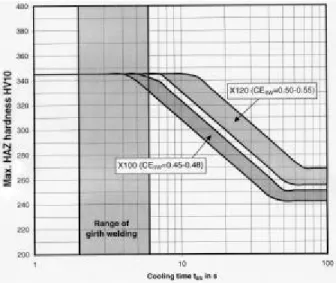
The carbon equivalent of high-strength linepipe steel grades on itself has no significant effect on the peak hardness under typical field welding conditions any more (short t8/5 cooling times, Figures 20 and
21). In girth welds, which are always characterised by cooling times of t8/5 = 2 to 6 s, the peak hardness of the root pass HAZ is initially
governed by a 100 % martensitic structure and therefore dependent only on the carbon content. This aspect should be taken into account when stipulating restricted carbon equivalents in standards and specifications for high-strength steels under discussion. The same is true of grade X 120, representing the highest strength level aimed at. Therefore, there is no difference in the base material’s cold cracking behaviour between grade X 100 and grade X 120.
Figure 20: Comparison of the hardenability of an older X 70 linepipe material with a modern X 100 linepipe material in respect of typical girth welding conditions (calculation acc. to Mannesmann formulas)
Therefore, it has to be emphasised that it is not the base material, but it is the filler weld metal deposited with ultra-high-strength basic vertical down electrodes that is more sensitive and therefore, plays the major role in respect of avoiding cold cracking when welding grade X 100 and particularly grade X 120 material. The preheating temperature to be selected must be appropriate to the weld metal’s chemistry and the
hydrogen input during welding.
This implies that the preheating temperature has to be such that hydrogen can adequately effuse from the ultra-high strength basic weld metal in the filling and cap passes before the weld cools to room temperature.
All these measures are commonplace today and do not imply very high additional costs. The manufacture of welding consumables matching grades X 100 and X 120, should be possible in principle for both SMA and GMAW.
Figure 21: Hardenability of linepipe steel grades X 100 and X 120 (calculation acc. to Mannesmann formulas)
CONCLUSIONS
The predicted growth in energy consumption in the coming decades necessitates severe efforts for transporting large amounts of natural gas to end users economically. Large-diameter pipelines serve as the best and the safest means of transport. This paper presents an overview of the current requirements for high strength steels and the associated developments. The technical possibilities are described. Also in the future, additional substantial improvements can be realised.
Several pipelines installed in Europe and North America in the past two decades show that the use of X 80 linepipe causes no problems with respect to mechanical properties and welding. The development work led to the conclusion that grade X 100 mechanical properties can be achieved. Crack arrest properties for certain pipe sizes were verified in full scale burst tests. The initial results of the work directed to developing grade X 120 are encouraging with respect to the properties of the base material.
Not only the steel grade, but also the usage factor and the operating pressure are increasing steadily. From the manufacturers’ point of view, certain points must be observed when using higher-strength material grades. The minimum thickness should be 12 mm and for grade X 80 pipe and 16 mm for grade X 100 pipe. An increase of the operating pressure combined with a smaller diameter and a constant wall thickness should be preferred to reducing the wall thickness. In any case, the thickness-to-diameter ratio of high strength large-diameter pipe should be in excess of 1% or better 1.5%.
The enormous pressure on the price of natural gas forces the pipeline operators to explore all possibilities to reduce the cost of pipeline projects in future. The pipe manufacturer can assist him in his endeavour by supplying high quality pipe. The effect of pipe quality on the reduction of project costs will be more substantial when the pipeline is constructed to the limit state design.
Finally, the pipe manufacturers make contributions to reducing operational costs of a pipeline over its life by determining through investigations the fatigue, corrosion and ageing behaviour of pipe and pipe materials. These properties have a significant bearing on the integrity of a pipeline and consequently the operating costs. These properties are currently being extensively studied. The knowledge gained from these studies can be made available to assist the pipeline operators when planning a new pipeline project or when estimating the residual life of ageing pipelines.
REFERENCES
/1/ M. K. Gräf and H.-G. Hillenbrand: “High Quality Pipe – a Prerequisite for Project Cost Reduction”, 11th PRCI-EPRG Joint Technical Meeting, Arlington, Virginia, April 1997
/2/ L. Barsanti, H.-G. Hillenbrand, G. Mannucci, G. Demofonti, and D. Harris: “Possible use of new materials for high pressure linepipe construction: An opening on X100 grade steel”, International Pipeline Conference, Calgary, Alberta, September 2002
/3/ M. D. Bishop, O. Reepmeyer, H.-G. Hillenbrand, J. Schröder and A. Liessem: “Longitudinal welded X80 pipes for a high temperature, high pressure steam pipeline”, 3 R international 41 (2002) No. 2
/4/ H. Engelmann, A. Engel, P. A. Peters, C. Düren and H. Müsch: “First use of large-diameter pipes of the steel GRS 550 TM (X80)”; 3R International 25 (1986), No. 4, 182 - 193
/5/ V. Chaudhari, H. P. Ritzmann, G. Wellnitz, H.-G. Hillenbrand and V. Willings: “German gas pipeline first to use new generation linepipe”; Oil & Gas Journal, January 1995
/6/ H.-G. Hillenbrand, K. A. Niederhoff, G. Hauck, E. Perteneder and G. Wellnitz: “Procedure, considerations for welding X80 linepipe established”; Oil & Gas Journal, Sept 15, 1997
/7/ V. Schwinn, P. Fluess and J. Bauer: "Production and progress work of plates for pipes with strength level of X80 and above", International Conference on the Application and Evaluation of high-grade linepipes in hostile Environments, Yokohama, Japan, November 2002
/8/ L. Barsanti, G. Pozzoli and H.-G. Hillenbrand: “Production and Field Weldability Evaluation of X100 Linepipe”, 13th Joint Meeting
PRCI-EPRG, New Orleans, USA 2001
/9/ H.-G. Hillenbrand, A. Liessem, G. Knauf, K. A. Niederhoff and J. Bauer: “Development of large-diameter pipe in grade X100 – State of the art report from the manufacturer’s point of view“, International pipeline technology conference, Brugge, Belgium, May 2000
/10/ G. Demofonti, G. Mannucci, D. Harris, H.-G. Hillenbrand and L. Barsanti: “Fracture behaviour of X100 gas pipeline by full scale tests”, International Conference on the Application and Evaluation of high-grade linepipe in hostile Environments, Yokohama, Japan, November 2002