9. Auxiliary Systems
AP1000 Design Control Document
9.3 Process Auxiliaries9.3.1 Compressed and Instrument Air System
The compressed and instrument air system (CAS) consists of three subsystems; instrument air, service air, and high-pressure air. Instrument air supplies compressed air for air-operated valves and dampers. Service air is supplied at outlets throughout the plant to power air-operated tools and is used as a motive force for air-powered pumps. The service air subsystem is also utilized as a supply source for breathing air. Individually packaged air purification equipment is used to produce breathing quality air for protection against airborne contamination. The high-pressure air subsystem supplies air to the main control room emergency habitability system (VES), the generator breaker package, and fire fighting apparatus recharge station. The high-pressure air subsystem also provides a connection for refilling the VES storage tanks from an offsite source. Major components of the compressed and instrument air system are located in the turbine building.
9.3.1.1 Design Basis 9.3.1.1.1 Safety Design Basis
The compressed and instrument air system serves no safety-related function other than containment isolation and therefore has no nuclear safety design basis except for containment isolation. See subsection 6.2.3 for the containment isolation system.
9.3.1.1.2 Power Generation Design Basis
The instrument air subsystem provides filtered, dried, and oil-free air for air-operated valves and dampers. The instrument air subsystem consists of two compressors and associated support equipment and controls that are powered from switchgear backed by the nonsafety-related onsite standby diesel generators as an investment protection category load. The subsystem provides high quality instrument air as specified in the ANSI/ISA S7.3 standard (Reference 9.3.8.1).
The service air subsystem provides filtered, dried, and oil-free compressed air for service outlets located throughout the plant. The service air subsystem consists of two compressors and their associated support equipment and controls. Plant breathing air requirements are satisfied by using the service air subsystem as a supply source. Individually packaged air purification equipment is used to improve the service air to Quality Verification Level D breathing air as defined in ANSI/CGA G-7.1.
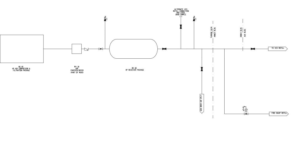
The high-pressure air subsystem consists of one compressor, its associated air purification system and controls, and a high-pressure receiver. It provides clean, oil-free, high-pressure air to recharge the main control room emergency habitability system cylinders, refill the individual fire fighting breathing air bottles, and recharge the generator breaker reservoir. Quality Verification Level E air as defined in ANSI/CGA G-7.1 is produced by this subsystem. See Section 6.4 for a description of the main control room habitability system.
9. Auxiliary Systems
AP1000 Design Control Document
9.3.1.2 System Description9.3.1.2.1 General Description
Classifications of components and equipment in the compressed and instrument air system are given in Section 3.2. In accordance with NUREG-1275, instrument air quality meets the manufacturer's standards for pneumatic equipment supplied as a part of the plant. Intake filters for instrument air, service air, and high-pressure air compressors remove particulates 10 microns and larger.
Instrument Air Subsystem
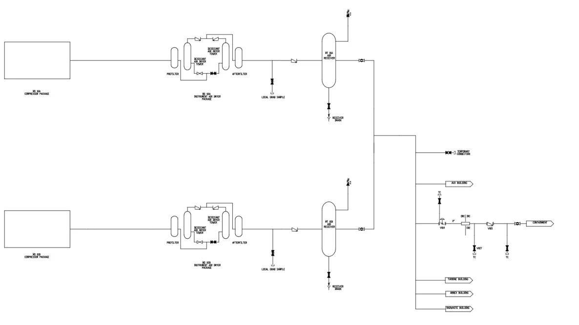
The instrument air subsystem consists of two 100 percent capacity parallel air supply trains discharging to a common air distribution system. An air compressor, dryer, controls, and receiver comprise one air supply train. The two compressor trains join to a single instrument air header downstream of the receivers.
Provisions are made to temporarily cross connect the instrument and service air subsystems at the distribution header.
The instrument air line to the containment is normally open; however, air flow to the containment is monitored and a high flow alarm is provided to indicate a possible instrument air line rupture inside containment. Safety-related air-operated valves supplied by the system are identified in Table 9.3.1-1. None of these valves require instrument air to perform their safety-related function. The valves with an active safety-related function fail in the safe position on loss of instrument air pressure.
One instrument air compressor train, including its air dryer and associated equipment and controls, can be connected to each of the nonsafety-related onsite standby diesel generators. The compressors are cooled by water supplied from the component cooling water system (CCS). Refer to subsection 9.2.2 for details. The instrument air subsystem is shown schematically in Figure 9.3.1-1. Major system components are described in Table 9.3.1-2.
Service Air Subsystem
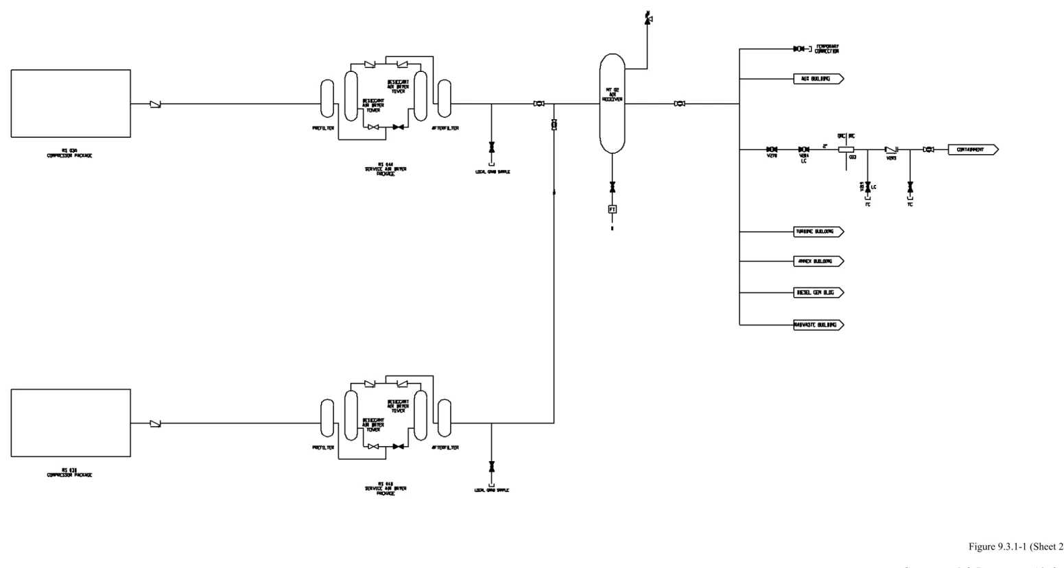
Two 100 percent capacity compressor trains are provided for the service air subsystem. These compressor trains consist of identical equipment and share a common air receiver that feeds the service air distribution system. Cooling water to the service air compressors is supplied from the component cooling water system. Refer to subsection 9.2.2 for details.
The service air line to containment is normally closed and is opened on an as-needed basis. The service air subsystem is shown schematically in Figure 9.3.1-1 and major system components are described in Table 9.3.1-3.
High-Pressure Air Subsystem
The high-pressure air subsystem consists of a high-pressure air compressor with an integral air purification system, controls, and a receiver.
9. Auxiliary Systems
AP1000 Design Control Document
The high-pressure air subsystem is manually operated and may be loaded on an onsite standby diesel generator. This subsystem supplies air to the main control room emergency habitability system, the generator breaker, and the fire fighting apparatus recharge station. The isolation valves to these locations are normally closed and are opened on an as-needed basis to refill the specified equipment air storage reservoirs. The high-pressure air subsystem is shown schematically in Figure 9.3.1-1 and major system components are described in Table 9.3.1-4.9.3.1.2.2 Component Description Instrument Air Subsystem
The instrument air subsystem consists of two air compressor trains. Each compressor train consists of a multistage, low-pressure, rotary screw, air compressor package, a desiccant dryer with a prefilter and afterfilter, and an air receiver. Each compressor package includes an intake filter, rotary screw compressor elements, silencer, intercooler, aftercooler, moisture separators, bleed-off cooler, oil cooler, oil reservoir, automatic load controls, relief valves, and a discharge air check valve. Each compressor train produces oil-free air.
Two instrument air receivers function as storage devices for compressed air. The receivers continue to supply the instrument air subsystem following a loss of the instrument air compressors until the receiver pressure drops below system requirements. Each air receiver is equipped with an automatic condensate drain valve and a pressure relief valve.
Two air dryer assemblies are provided for the instrument air subsystem. Each dryer assembly consists of a desiccant-filled, twin tower design. One tower may be used to dry air while the other tower goes through regeneration. When instrumentation senses a high dew point, the towers switch. The former operating tower then undergoes regeneration while the regenerated tower drys the instrument air.
Each dryer assembly includes a coalescing prefilter that removes oil aerosols and moisture droplets, as well as an afterfilter to remove desiccant dust.
The instrument air subsystem supplies ANSI/ISA S-7.3 high quality instrument air. Table 9.3.1-2 provides design information for the main components associated with the instrument air subsystem.
Service Air Subsystem
The service air subsystem consists of two air compressor trains. Each compressor train consists of a multistage, low-pressure, rotary screw, air compressor package, and a desiccant dryer with a prefilter and afterfilter. A common air receiver is provided for the two trains. Each compressor package includes an intake filter, rotary screw compressor elements, silencer, intercooler, aftercooler, moisture separators, bleed-off cooler, oil cooler, oil reservoir, automatic load controls, relief valves, and a discharge air check valve. Each compressor train produces oil-free air. The common service air receiver functions as a storage device for compressed air. This air receiver is equipped with an automatic condensate drain valve and a pressure relief valve.
9. Auxiliary Systems
AP1000 Design Control Document
Two air dryer assemblies are provided for the service air subsystem. Each dryer assembly consists of a desiccant-filled, twin tower design. One tower may be used to dry air while the other tower goes through regeneration. When instrumentation senses a high dew point, the towers switch. The former operating tower then undergoes regeneration while the regenerated tower dries the service air.Each dryer assembly includes a coalescing prefilter that removes oil aerosols and moisture droplets, as well as an afterfilter to remove desiccant dust.
Table 9.3.1-3 provides design information for the main components associated with the service air subsystem.
High-Pressure Air Subsystem
The high-pressure air subsystem utilizes an air-cooled, oil-lubricated, four-stage, reciprocating-air compressor with an integral air purification system to produce oil-free air for high-pressure applications. The compressor train includes an intake filter, air-cooled intercoolers, interstage oil/water separators, an air-cooled aftercooler, a final oil/water separator, relief valves, an air purification system, discharge check valves, and a high-pressure receiver.
The high-pressure air subsystem supplies ANSI/CGA G-7.1 Quality Verification Level E air. See Table 9.3.1-4 for the design parameters for this system.
9.3.1.2.3 System Operation
Instrument Air Subsystem
The instrument air compressors are operated by a local pressure controller located in the instrument air distribution header, which can be programmed for various sequences of operation. Normally one compressor runs continuously loading and unloading as required to supply compressed air demand. The second compressor serves as a backup and starts automatically if the first unit fails or if demand exceeds the capacity of the operating compressor.
Air from the instrument air subsystem compressor packages discharges to the air dryers and then to the receivers where it is distributed to air-operated valves and dampers throughout the plant. Instrument air pressure is reduced by pressure regulators at the pneumatic component as required. The onsite standby power system (diesel generators) provides an alternate source of electrical power for the instrument air compressor trains. One compressor train is supplied from each electrical load group.
Service Air Subsystem
The service air subsystem compressors are operated by a local controller that can be programmed for various sequences of operation. Normally one compressor runs continuously and loads and unloads as required to supply service air demand. The second compressor serves as a backup and starts automatically if the first compressor fails or demand exceeds the capacity of the operating compressor. Air from each service air subsystem compressor package discharges to an air dryer
9. Auxiliary Systems
AP1000 Design Control Document
and then to the common receiver. Service air flows from the receiver to the various service air outlets throughout the plant.Breathing air can be obtained from any service air subsystem outlet by attaching a portable individually packaged air purification system. The breathing air purification package consists of replaceable cartridge-type filters, a pressure regulator, carbon monoxide monitoring equipment, air supply hoses, and air supply devices. Carbon monoxide is controlled by a catalytic conversion to carbon dioxide within the package. Breathing air of a Quality Verification Level D or better is supplied to personnel from the packaged purification system in accordance with the requirements of ANSI/CGA G-7.1.
High-Pressure Air Subsystem
The high-pressure air subsystem is operated when a specific high-pressure source requires refilling to replace air lost to leakage or expended during plant operations. System isolation valves to the specified equipment are manually opened and the equipment storage reservoir is replenished from the high-pressure receiver. The compressor is then started to replenish the air stored in the high-pressure receiver.
Breathing air of a Quality Verification Level E is supplied from the integral high-pressure air purification system in accordance with the requirements of ANSI/CGA G-7.1. This integral air purification system utilizes a series of replaceable cartridge-type filters to produce breathing quality air. Breathing air connections of the high-pressure air subsystem are incompatible with the breathing air connections of the service air subsystem. Carbon monoxide is controlled by a catalytic conversion to carbon dioxide within the package.
The onsite standby power system (diesel generators) provides an alternate source of electrical power for the high-pressure air compressor.
9.3.1.3 Safety Evaluation
The compressed and instrument air system has no safety-related function other than containment isolation and therefore requires no nuclear safety evaluation. Containment isolation functions are described in subsection 6.2.3.
The compressed and instrument air system is required for normal operation and startup of the plant. Air-operated valves that are essential for safe shutdown and accident mitigation are designed to actuate to the fail-safe position upon loss of air pressure. These air-operated valves utilize safety-related solenoid valves to control the air supply.
The instrument and service air subsystems are classified as moderate-energy systems. There are no adverse effects on safety-related components associated with a postulated failure of the instrument and service air piping.
The high-pressure air subsystem is classified as a high-energy system. The high-pressure compressor and receiver are located in the turbine building, which contains no safety-related, equipment or structures. Air piping routed in safety-related areas is 1 inch or less in diameter and the dynamic consequences of a rupture are not required to be analyzed. The high-pressure air
9. Auxiliary Systems
AP1000 Design Control Document
subsystem is not required to operate following a design basis accident nor is it used for safe shutdown of the plant.9.3.1.4 Tests and Inspections
System components, such as the air compressors and air dryers, are inspected or tested prior to installation. The installed compressed air system is inspected, tested, and operated to verify that it meets its performance requirements, including operational sequences and alarm functions. Air compressors and associated components on standby are checked and operated periodically. Desiccant in the air dryers is changed when required.
Sample points are provided downstream of the air dryers in both the instrument and service air subsystems and downstream of the purifier in the high-pressure air subsystem. Periodic checks are made to ensure high quality instrument air as specified in the ANSI/ISA S-7.3 standard. Periodic checks on the high-pressure air compressor are made on a regular basis to verify that the breathing air meets the Quality Verification Level E as indicated in the ANSI/CGA G-7.1 standard. During the initial plant testing prior to reactor startup, safety systems utilizing instrument air are tested as part of the safety system test to verify fail-safe operation of air-operated valves upon sudden loss of instrument air or gradual reduction of air pressure as described in Regulatory Guide 1.68.3. Section 1.9 summarizes conformance with Regulatory Guide 1.68.
9.3.1.5 Instrumentation Applications
An instrumentation package is included with each of the instrument and service air compressors. Each package consists of temperature and pressure transducers, indicators, and automatic protection devices. The temperature and pressure transducers support the automatic control modes of compressor operation. A manual mode of operation is also provided for each control system. Compressed air system indication and control are available in the main control room.
The high-pressure air subsystem includes pressure and carbon monoxide instrumentation, automatic protection devices, and temperature indication.
9.3.2 Plant Gas System
The plant gas system (PGS) provides hydrogen, carbon dioxide, and nitrogen gases to the plant systems as required.
Other gases, such as oxygen, methane, acetylene, and argon, are supplied in smaller individual containers and are not supplied by the plant gas system.
9.3.2.1 Design Basis 9.3.2.1.1 Safety Design Basis
The plant gas system serves no safety-related function and therefore has no nuclear safety design basis.
9. Auxiliary Systems
AP1000 Design Control Document
9.3.2.1.2 Power Generation Design BasisThe nitrogen portion of the plant gas system supplies nitrogen for pressurizing, blanketing, and purging of various plant components.
The hydrogen gas portion of the plant gas system supplies hydrogen to the main plant electrical generator for cooling as well as to other plant auxiliary systems.
The carbon dioxide portion of the plant gas system supplies carbon dioxide to the generator for purging of hydrogen and air during layup or plant outages.
9.3.2.2 System Description
Classification of equipment and components is given in Section 3.2.
9.3.2.2.1 General Description
The nitrogen portion of the plant gas system is a packaged system consisting of a liquid nitrogen storage tank and vaporizers. Nitrogen gas is supplied in both a high-pressure and a low-pressure subsystem. The high-pressure subsystem uses a pump to pressurize the gas supplying the accumulators in the passive core cooling system. The high-pressure supply is then reduced to supply makeup to the reactor coolant drain tank for purging and blanketing. Low-pressure nitrogen is provided for component purging, layup/blanketing, and pressurization.
The main steam isolation valves (MSIVs) and main feedwater isolation valves (MFIVs) use compressed nitrogen stored within the valve operators as the motive force to close the valves. The main steam isolation valves are described in subsection 10.3.2.2.4 and the main feedwater isolation valves are described in subsection 10.4.7.2.2. Nitrogen makeup for these valves (if needed) is provided from portable high-pressure nitrogen bottles using temporary connections on the valves.
The packaged nitrogen system is located in the gas storage area in the yard.
The low-pressure hydrogen gas portion of the plant gas system is a packaged system consisting of a liquid hydrogen storage tank and vaporizers to supply hydrogen gas to the main generator for generator cooling and the demineralized water transfer and storage system to support removal of dissolved oxygen. The packaged hydrogen system is located in the gas storage area in the yard. A separate high-pressure hydrogen packaged system supplies hydrogen to the chemical and volume control to support removal of dissolved oxygen in the RCS. The hydrogen for this system is stored as a compressed gas in high-pressure tanks (gas bottles). The high-pressure hydrogen supply package system is located outdoors adjacent to the turbine building.
The gas storage area in the yard is located a sufficient distance away from safety-related structures, systems, and components that they are protected from the effects of explosion, flammable vapor cloud, and fire. The gas storage area is located a sufficient distance away from the air inlet to the control room so that the control room operators are protected from potential toxic effects and asphyxiation. The location of the gas storage area shown in Figure 1.2-2 is an acceptable location,
9. Auxiliary Systems
AP1000 Design Control Document
but that location is not part of the certified design. The location of the gas storage area is a site-specific determination.The carbon dioxide portion of the plant gas system, which is a packaged system consisting of one liquid storage tank and a vaporizer, produces gaseous carbon dioxide to purge the main generator. This packaged system is located in the gas storage area in the yard.
Liquid gas storage tanks are built in accordance with the ASME Boiler and Pressure Vessel Code, Section VIII, Division 1, 1998 Edition, 2000 Addenda.
9.3.2.2.2 Component Description Liquid Nitrogen Storage Tank
Liquid nitrogen is stored under its own vapor pressure as a saturated liquid in a dual wall tank. This tank supplies nitrogen for the high- and low-pressure nitrogen gas systems. The annular space between the inner and outer tank walls is filled with insulation and evacuated when the tank is cold.
Liquid Nitrogen Pump
A cryogenic liquid nitrogen pump is utilized to provide a supply of high-pressure nitrogen. It is a single-cylinder, positive displacement pump with the entire "cold" pumping assembly enclosed in a vacuum-jacket, which permits the pump to remain cold in the standby condition.
Nitrogen High-Pressure Ambient Air Vaporizer
Liquid nitrogen is vaporized by a high-pressure natural convection vaporizer, which vaporizes and superheats cryogenic nitrogen using heat from the ambient air.
Nitrogen Low-Pressure Ambient Air Vaporizer
The low-pressure vaporizer unit has two parallel banks. In the event of frost buildup on the active bank, flow is redirected to the opposite bank while the other bank defrosts.
Gaseous Nitrogen Storage Tubes
Gaseous nitrogen storage tubes are provided. These storage tubes provide short-term storage for high-pressure nitrogen.
Liquid Hydrogen Storage Tank
Cryogenic liquid hydrogen is stored in a dual wall tank. The annular space between the walls is insulated using a vacuum and wrapped reflective insulation to minimize heat leakage.
9. Auxiliary Systems
AP1000 Design Control Document
Hydrogen Ambient Air VaporizersTwo parallel banks of vaporizers are provided. In the event of frost buildup on the active bank, flow is redirected to the opposite bank while the other bank defrosts.
Gaseous Hydrogen Storage Tanks
Gaseous hydrogen storage tanks are used to provide for storage of high-pressure hydrogen.
Liquid Carbon Dioxide Storage Tank
Cryogenic liquid carbon dioxide is stored in an insulated single wall tank to minimize heat transfer.
Carbon Dioxide Electric Vaporizer
The liquid carbon dioxide is vaporized using electric resistance heating.
9.3.2.2.3 System Operation
Liquid nitrogen is stored under its own vapor pressure as a saturated liquid. An economizer circuit minimizes product loss due to vessel boiloff under low-flow conditions. A pressure build circuit maintains pressure at a suitable level above line delivery pressures. For the low-pressure system, liquid is withdrawn, vaporized, and pressure regulated prior to delivery to the low-pressure nitrogen manifold. For high-pressure nitrogen, liquid is withdrawn by the pump, vaporized, and discharged into the high-pressure storage tubes. The gas is then pressure regulated and routed to the high-pressure nitrogen manifold.
Liquid hydrogen is stored in a cryogenic storage vessel complete with an economizer circuit and a pressure build circuit. Ambient air vaporizers turn the liquid to a gas, which is pressure regulated. See subsection 9.3.6 for further discussion of hydrogen use in the chemical and volume control system. The hydrogen used in the chemical and volume control system is supplied from the high-pressure gaseous hydrogen storage tanks.
Liquid carbon dioxide is distributed from a cryogenic storage vessel. An electric vaporizer turns the liquid to a gas, which is pressure regulated for the generator purge.
9.3.2.3 Safety Evaluation
The plant gas system is required for normal plant operation and startup of the plant. The plant gas system is not required for safe shutdown of the plant. Therefore, it is not designed to meet seismic Category I requirements or single failure criterion. The plant gas system serves no safety-related function and has no safety design basis.
The nitrogen, the carbon dioxide, and the hydrogen system storage is located outside of the main buildings. The storage tanks are analyzed as a potential missile source. Refer to Section 3.5. Accidents involving accidental detonations of hydrogen from the onsite storage of compressed or liquid hydrogen are evaluated for damage to safety–related structures, systems, and components.
9. Auxiliary Systems
AP1000 Design Control Document
Refer to Section 2.2. For explosions, the plant gas system is designed for conformance with Regulatory Guide 1.91.The effects of the plant gas system on main control room habitability are addressed in Section 6.4. The main control room habitability evaluation considers the flammability and asphyxiation potential for these gases.
9.3.2.4 Tests and Inspections 9.3.2.4.1 Storage Vessel Testing
• Each storage vessel is hydrostatically tested in accordance with the ASME Boiler and Pressure Vessel Code, Section VIII, Division 1, 1998.
• Each vessel is examined using the magnetic particle method.
9.3.2.5 Instrumentation Requirements
Low-level indication alarms are provided in the main control room for the liquid nitrogen and the hydrogen storage tank levels.
Temperature and pressure indications are provided at various points within the plant gas system.
9.3.3 Primary Sampling System
The AP1000 primary sampling system (PSS) performs the following functions: • Collects in normal operation mode both liquid and gaseous samples • Provides for local grab samples during normal operation mode
This system includes equipment to collect representative samples of the various process fluids, including reactor coolant system and containment air, in a manner that adheres to as-low-as-reasonably-achievable (ALARA) principles during normal and post-accident conditions. The primary sampling system also includes provisions to route sample flow to a laboratory for continuous or intermittent sample analysis, as desired.
The primary sampling system provides a way to monitor the plant and various system conditions using the collected and analyzed samples.
A safety-related containment hydrogen analyzer provided to monitor the containment atmosphere following a postulated loss-of-coolant accident (LOCA) is described in subsection 6.2.4. A discussion of process radiation monitoring is provided in Section 11.5.
9. Auxiliary Systems
AP1000 Design Control Document
9.3.3.1 Design Bases9.3.3.1.1 Safety Design Basis
The primary sampling system has no safety-related function, other than containment isolation and therefore requires no nuclear safety evaluation, other than containment isolation, which is described in subsection 6.2.3.
The equipment and seismic classification are discussed in Section 3.2.
9.3.3.1.2 Power Generation Design Basis
9.3.3.1.2.1 Sampling During Normal Plant Operations
During normal operation, the primary sampling system collects representative samples of fluids in the reactor coolant system (RCS) and auxiliary primary systems process streams and the containment atmosphere for analysis, as listed in Table 9.3.3-1. Local sample points, as listed in Table 9.3.3-2, are provided at various process points of the systems.
The results of the sample analyses are used to perform the following functions: • Monitor core reactivity
• Monitor fuel rod integrity
• Evaluate ion exchanger (demineralizer) and filter performance • Specify chemical additions to the various systems;
• Maintain acceptable hydrogen levels in the reactor coolant system • Detect radioactive material leakage
The measurements are used to evaluate water chemistry and to recommend corrective action by the laboratory staff.
The primary sampling system component classification is provided in Section 3.2.
9.3.3.1.2.2 Post-Accident Sampling
The primary sampling system does not include specific post-accident sampling capability. However, in accordance with Reference 5 there are contingency plans for obtaining and analyzing highly radioactive samples of reactor coolant, containment sump, and containment atmosphere. These plans include the procedures to analyze, during the later stages of accident response, reactor coolant for boron, containment atmosphere for hydrogen and fission products, and containment sump water for pH.
The primary means of containment atmosphere hydrogen analysis is the hydrogen analyzer described in subsection 6.2.4, which is not part of the post-accident sampling capabilities.
9. Auxiliary Systems
AP1000 Design Control Document
9.3.3.2 System DescriptionThe primary sampling system is a manually operated system. It collects representative samples of fluids from the reactor coolant system and various primary auxiliary system process streams for analysis by the plant operating staff. This sampling process is performed during normal plant operations.
The primary sampling system consists of two separate portions: the liquid sampling portion and the gas sampling portion.
9.3.3.2.1 Nuclear Sampling System - Liquids
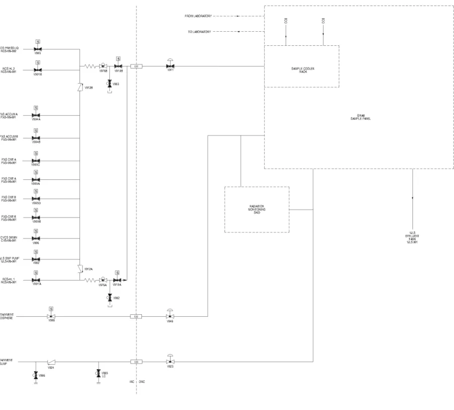
The liquid sampling portion of the primary sampling system collects samples from the reactor coolant system and the auxiliary systems and transports them to a common location in a sample room in the auxiliary building. Control and instrumentation is provided for safe, reliable operation. This portion of the system uses 1/4 inch stainless steel tubing. The small tubing flow area limits flow to less than chemical and volume control system makeup capacity in the event of a leak in the sampling lines. Dissolved gases in the reactor coolant system are collected in this system also.
Sample flow is routed to a grab sampling unit. This unit is in an enclosure, which controls the spread of contamination and provides shielding. The grab sampling unit is further shielded by a concrete wall to minimize radiation exposure.
Valves inside the grab sampling unit have long handles extending outside the enclosure and are manually operated. This arrangement allows the operator to obtain a sample quickly with minimum radiation exposure. A schematic diagram is provided on the front of the grab sampling unit to illustrate the tube routing inside.
Since the motive force during normal operations is the system pressure, the sampling system is designed to reactor coolant system pressure. If system pressure is not available, an eductor supplies the motive force for sample collection.
A direct line from the grab sampling unit to the laboratory provides the capability for continuous liquid sampling and analysis with online monitors.
Prior to the collection of liquid samples either in the laboratory or in the grab sampling unit, the lines are purged with source liquid to provide representative samples. The purging flow returns to the effluent holdup tank of the liquid radwaste system.
Figure 9.3.3-1 is a simplified sketch of the primary sampling system.
9.3.3.2.2 Nuclear Sampling System - Gaseous
This portion of the primary sampling system collects gaseous samples from the containment atmosphere. Gaseous sampling is conducted in the sample room in the auxiliary building, and it shares with the liquid sampling portion the grab sampling unit and the control panel. However, it uses 3/8 inch stainless steel tubing. Similar to the liquid sampling system, the gas sample
9. Auxiliary Systems
AP1000 Design Control Document
subsystem is also manually operated with extension stems on the valves. Only grab samples are collected for the gas sampling process. The lines are purged prior to sample collection to provide representative samples. The purged gas returns to the containment sump.Provisions are also made to dilute the gas sample. The dilution process uses nitrogen from a local gas bottle.
The gas sampling system uses an ejector as the motive force for sample collection. The ejector uses nitrogen from a local gas bottle as the motive force.
9.3.3.3 Containment Isolation Valves
Containment isolation valves are classified as Safety Class B. The lines penetrating the reactor containment meet the containment isolation criteria. See subsection 6.2.3.
Three lines penetrate the containment. One line carries the liquid samples from their sources to the grab sampling unit or the laboratory. The second line carries the containment air samples from their source to the sampling unit. The third line returns the liquid or containment air sampling flows to the containment sump. The valves fail closed.
These valves close on a containment isolation signal. In addition, the outside containment isolation valve in the liquid sampling path closes on a high sampling flow temperature or high radiation downstream of the sample cooler. This prevents the operator from working with high temperature fluid and minimizes the possibility of operator injury.
9.3.3.4 System Operation and Performance
The primary sampling system is manually operated. The tubing size and sampling flow rate are selected throughout the system to reduce the amount of purge flow and to provide turbulent sampling flow (to collect representative samples). A delay coil of tubing is installed inside containment to provide at least 60 seconds of transit time for the sampling fluid to exit the containment from the hot leg. This 60-second delay is needed for N-16 decay.
9.3.3.5 Design Evaluation
The primary sampling system has no safety function, other than containment isolation and therefore requires no nuclear safety evaluation, other than containment isolation.
Subsection 6.2.3 provides the safety evaluation for the containment isolation system. Primary sampling system lines penetrating the containment are isolated at the containment boundary by valves that close upon receipt of a containment isolation signal and by manual actuation. (See subsection 6.2.3 for a discussion of containment isolation.)
The primary sampling system connects to the reactor coolant system and the passive core cooling system (PXS) and therefore provides features consistent with ANSI standards and ASME codes to protect these system pressure boundaries.
9. Auxiliary Systems
AP1000 Design Control Document
The primary sampling system is not required for accident mitigation or post-accident sampling; but there are plans for obtaining and analyzing highly radioactive samples of reactor coolant, containment sump, and containment atmosphere in accordance with Reference 5.The acceptability of the design of the primary sampling system is based on specific general design criteria and regulatory guides. The design of the primary sampling system is consistent with the criteria set forth in subsection 9.3.2, "Process and Post-Accident Sampling Systems," of the NRC's Standard Review Plan (Reference 6) as modified by Reference 5. The specific general design criteria identified in the Standard Review Plan are General Design Criteria 1, 2, 13, 14, 26, 41, 60, 63, and 64. See Section 1.9 for a discussion of regulatory compliance.
9.3.3.6 Inspection and Testing Requirements 9.3.3.6.1 Preoperational Testing
Preoperational testing is performed after installation and prior to plant startup. Proper operation of the primary sampling system is demonstrated during preoperational testing. A sample is drawn from the reactor coolant system, containment atmosphere and other sample points via the sampling system in order to verify proper system operation.
9.3.3.6.2 Operational Testing
The proper operation and availability of the liquid and gaseous sampling subsystems are proven by continued proper sampling operations.
9.3.3.7 Instrumentation Requirements
The primary sampling system uses indicators as required to facilitate manual operation and to verify sample conditions before samples are drawn. Radiation monitoring instruments are used to monitor the incoming fluid (liquid or gas) radioactivity level.
The temperature indicator inside the grab sampling unit provides a signal to close the outside containment isolation valve when the sampling flow temperature exceeds pre-set limits. Likewise, the radiation monitors also provide a signal to close the outside containment isolation valves when excessive radiation levels are detected, for operator protection.
9.3.4 Secondary Sampling System
The secondary sampling system (SSS) delivers representative samples of fluids from secondary systems to sample analyzer packages. Continuous online secondary chemistry monitoring detects impurity ingress and provides early diagnosis of system chemistry excursions in the plant. Secondary sampling monitors send control signals to the turbine island chemical feed system that automatically injects corrosion control chemicals into the condensate and feedwater systems.
9. Auxiliary Systems
AP1000 Design Control Document
9.3.4.1 Design Basis9.3.4.1.1 Safety Design Basis
The secondary sampling system serves no safety-related function and therefore has no nuclear safety design basis.
9.3.4.1.2 Power Generation Design Basis
The secondary sampling system monitors water samples from the condensate, feedwater, main steam, heater drain, steam generator blowdown, auxiliary steam supply, and condensate polishing systems, as listed in Table 9.3.4-1 and Table 9.3.4-2. Water quality analyses are performed on these samples to determine the following:
• pH
• Conductivity levels (specific and cation) • Dissolved oxygen level
• Residual oxygen scavenger • Sodium content
• Sulfate content.
The sample analyses are used to control water chemistry and to permit appropriate corrective action.
9.3.4.2 System Description
Classification of equipment and components for the secondary sampling system is given in Section 3.2. The sample points listed in Table 9.3.4-1 are continuously monitored. The sample points listed in Table 9.3.4-2 are selectively monitored (where a single analyzer package can be used to selectively monitor multiple sample points).
Sample analysis data from the continuous analyzers is recorded using computer systems that also provide trending capability of the measured process parameters. Measurements are used to automatically control condensate and feedwater system pH and dissolved oxygen levels by chemical addition. Refer to subsection 10.4.11 for further discussion of the turbine island chemical feed system.
Samples are analyzed and the results are used for automatic or manual control of the plant secondary water chemistry. After being analyzed, pure samples are returned to the condensate system. Sample lines containing reagents and those from sink drains are collected in the waste water system and processed for disposal. Each sample line has a grab sampling capability for laboratory analysis.
Roughing coolers are provided for the samples whose temperatures exceed 125°F. Samples are cooled to approximately 77°F by chilled water supplied to trim coolers.
9. Auxiliary Systems
AP1000 Design Control Document
9.3.4.3 Safety EvaluationThe secondary sampling system has no safety-related function and therefore requires no nuclear safety evaluation.
9.3.4.4 Tests and Inspections
Proper operation of the secondary sampling system is initially demonstrated during preoperational testing.
The system draws continuous and selective samples from the condensate, feedwater, main steam, and steam generator blowdown systems for automatic or manual water quality analysis. Calibration of the analyzers is checked periodically through laboratory analysis of a grab sample from the same process flow. The output of the continuous analyzers is recorded, and abnormal values are evaluated.
9.3.4.5 Instrumentation Applications
The secondary sampling system uses pressure, temperature, and flow indicators to facilitate operation and to verify sample conditions.
9.3.5 Equipment and Floor Drainage Systems
The equipment and floor drainage systems collect liquid wastes from equipment and floor drains during normal operation, startup, shutdown, and refueling. The liquid wastes are then transferred to appropriate processing and disposal systems.
Equipment and floor drainage is segregated according to the type of waste. Liquid wastes are classified and segregated for collection as follows:
• Radioactive liquid waste • Nonradioactive liquid waste
• Chemical and detergent liquid waste • Oily liquid waste
9.3.5.1 Design Basis 9.3.5.1.1 Safety Design Basis
The equipment and floor drainage systems are nonsafety-related and serve no safety-related function except for the backflow preventers in drain lines from containment cavities to the containment sump. No nuclear safety design basis is required except for the backflow preventers described in Section 11.2. Single active failures do not prevent the proper function of the safety-related backflow preventers.
The floor drainage systems and equipment are designed to prevent damage to safety-related systems, structures, and equipment. Safety-related components are not damaged as a result of
9. Auxiliary Systems
AP1000 Design Control Document
equipment and floor drain components failure from a seismic event. Floor drainage systems and equipment single failures will not prevent the proper function of any safety-related equipment.9.3.5.1.2 Power Generation Design Basis
Nonradioactive liquid waste sumps and drain tanks that can be potentially radioactive during normal plant operation are provided with sampling capabilities. There are no permanent connections between the radioactive drain system and nonradioactive piping. Provisions for temporary diversion of contaminated water from normally nonradioactive drains to the liquid radwaste system are included.
Equipment drains are adequately sized to meet the flow requirements.
Radioactive sump vents are directed to the ventilation system exhaust ducts, serving the areas where the sump is located. The containment sump vents directly to the containment.
Drainage systems are drained by gravity. The slope of the drain lines is 1/8 inch per foot as a minimum except for the embedded drain piping for area 2 of the auxiliary building, elevation 66'-6". At this level, the slope of the drain lines is 1/16 inch per foot minimum. The drainage systems are designed not to compromise the integrity of the areas maintained under a slight negative pressure during normal plant operation. This is achieved by avoiding cross connection with adjacent areas that are not maintained under a slight negative pressure. Radioactive drain systems are designed to avoid crud traps and to minimize drain traps. Sump and drain tank pumps discharge at a flowrate adequate to prevent sump overflow for drain rates anticipated during normal plant operation, maintenance, decontamination, fire suppression system testing, and fire fighting activities. Sump and drain tank capacities provide a live storage capacity consistent with an operating period of approximately 10 minutes with one pump operating as a minimum. The containment sump pumping time between high and low level is approximately 3 minutes.
Plugging of the drain headers is minimized by designing them large enough to accommodate more than the design flow and by making the flow path as straight as possible. Drain headers are at least 4 inches in diameter.
9.3.5.2 System Description 9.3.5.2.1 General Description
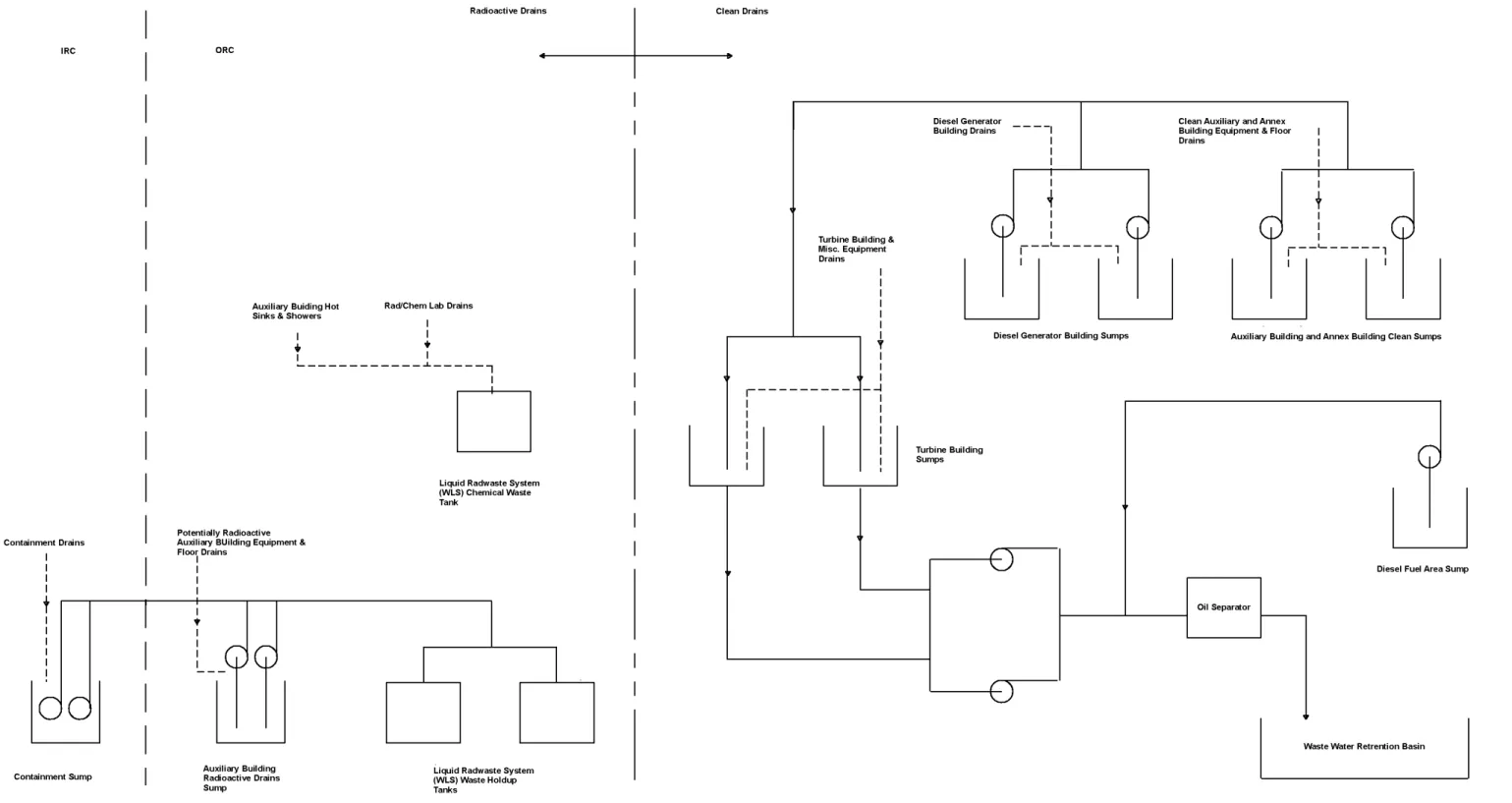
The drainage systems include collection piping, equipment drains, floor drains, vents, traps, cleanouts, sampling connections, valves, collection sumps, drain tanks, pumps, and discharge piping. The general arrangement of the drainage systems is shown on Figure 9.3.5-1.
Radioactive Wastes
The radioactive waste drain system is arranged to receive inputs from the radiologically controlled areas of the auxiliary, annex, and radwaste buildings based on segregation of the liquid wastes
9. Auxiliary Systems
AP1000 Design Control Document
into chemical and nonchemical drains. The radioactive waste drain system collects radioactive liquid wastes at atmospheric pressure from equipment and floor drainage of the radioactive portions of the auxiliary building, annex building, and radwaste building and directs these wastes to a centrally located sump located in the auxiliary building. The contents of the sump are pumped to the liquid radwaste system tanks. Drainage lines from the negative pressure boundary areas of the auxiliary, radwaste, and annex buildings do not terminate outside the negative pressure boundary without a normally closed valve or plugged drain to maintain the integrity of the negative pressure boundary.The liquid radwaste system collects radioactive and borated liquid wastes from equipment and floor drains in containment. Waste from the equipment drains inside containment is drained to the reactor coolant drain tank. The liquid waste from floor drains, fan coolers, and the containment wall gutter inside containment is drained to the containment sump. The contents of the drain tank and sump are pumped out of containment for processing by the liquid radwaste system. Refer to Section 11.2 for further details.
The sumps, pumps, and associated valves for the drain systems are located outside of high-radiation areas to the extent practical.
Nonradioactive and Potentially Radioactive Waste Drains
The waste water system collects nonradioactive waste from floor and equipment drains in auxiliary, annex, turbine, and diesel generator building sumps or tanks. Selected normally nonradioactive liquid waste sumps and tanks are monitored for radioactivity to determine whether the liquid wastes have been inadvertently contaminated. If contaminated, the wastes are diverted to the liquid radwaste system for processing and ultimate disposal. Refer to subsection 9.2.9 for further details. Drainage lines from the positive pressure boundary areas of the auxiliary building do not terminate outside the positive pressure boundary without a closed valve, plugged drain, or water seal to maintain the integrity of the positive pressure boundary.
Chemical Waste Drains
The radioactive waste drain system collects chemical wastes from the auxiliary building chemical laboratory and decontamination solution drains from the annex building and directs these wastes to the chemical waste tank of the liquid radwaste system.
Detergent Waste Drains
The laundry and respirator cleaning functions that generate detergent wastes are performed offsite. Detergent wastes from hot sinks and showers are routed to the chemical waste tank.
Oily Waste Drains
The waste water system collects nonradioactive, oily, liquid waste in drain tanks and sumps. Drain tank and sump liquid wastes are pumped through an oil separator prior to further processing. The oil is collected in a tank for disposal.
9. Auxiliary Systems
AP1000 Design Control Document
Sampling for oil in the waste holdup tank of the liquid radwaste system is provided to detect oil contamination before the ion exchanger resins are damaged. Oily water is pumped from the tank through an oil adsorbing bag filter before further processing. The spent bag filters are transferred to drums and stored in the radwaste building as described in Section 11.4.9.3.5.2.2 Component Description
General description and summaries of the design requirements for these components are provided below. Key equipment parameters are contained in Tables 9.3.5-1 and 11.2-2. Principal construction codes and standards and the classification applicable to the floor and equipment drainage systems are listed in Section 3.2.
Sumps and Drain Tanks
In general, the inlet drain lines to the sump or drain tank are kept submerged a minimum of 6 inches below pump shutoff level to prevent backgassing. The containment sump inlet is submerged.
Sumps are covered to keep out debris. Covers are removable, or manholes are provided for access. The total capacity of each sump includes a 10 percent freeboard allowance to permit operation of high-high level alarms and associated controls before the overflow point is reached.
Each sump is fitted with a vent connection to exhaust potential sump gases into the VAS exhaust system. Nonradioactive drain tanks are vented to the atmosphere. The reactor coolant drain tank is vented to the gaseous radwaste system (Section 11.3). Where necessary for the control of airborne radioactivity, the sump vents are routed to the ventilation system exhaust duct for the room. Radioactive sumps are stainless steel construction. Nonradioactive collection sumps are constructed of concrete with corrosion resistant coating or liner.
Sump and Drain Tank Pumps
Sumps outside containment are provided with air diaphragm pumps mounted on the sump cover plate. Pumps are equipped with reliable, mechanical diaphragms of demonstrated acceptable design that are easy to maintain. Pumps and associated piping connections and accessories are designed for easy replacement of pump diaphragms. The containment sump pumps are described in Section 11.2. The turbine building sump pumps are described in subsection 9.2.9.
Valves
Air-operated valves are provided for on/off functions of air supply to the sump pump diaphragms. Swing check valves, where provided, are installed in horizontal pipe runs. Pressure control valves are provided to control air supply pressure to the sump pump diaphragms. Manual ball valves are provided for maintenance purposes.
9. Auxiliary Systems
AP1000 Design Control Document
9.3.5.2.3 System OperationThe equipment and floor drainage systems operate during all modes of normal plant operation. Liquid wastes drain by gravity to collection tanks or sumps. Drainage flowrates vary based on the status of the plant. Sump pumps disposing of collected radioactive wastes discharge to the liquid radwaste system for further processing. Nonradioactive liquid wastes are discharged to the waste water system.
Pump operation is automatic with manual override. The pumps are automatically started and stopped by preset high, high-high, and low level instrumentation.
Where sumps are provided with two pumps, the capability is provided to allow equalizing the operational period of each pump. For the radioactive waste drain system, when the first pump is started on high level, a portion of the flow is recycled to allow recirculation of the flow through a mixing eductor.
The sump and drain tank pumps are not required to operate during design basis accidents. Sump pumps in the containment are interlocked with the associated containment isolation valves. The pumps trip and the isolation valves close on receipt of containment isolation signals (see subsection 6.2.3).
The equipment and floor drainage systems can be operated either automatically or manually for cleanup following an accident, including fire, provided that the compressed and instrument air system and ac power are available, and the drainage systems and support systems are not disabled by the event.
9.3.5.2.4 Instrumentation Applications
Level indication is provided in the main control room for the sump in-containment to provide indication of the presence of reactor coolant from unidentified leaks (refer to subsection 5.2.5). The sump and the drain tank outside containment are monitored for water level. On high sump or tank level, the solenoid-operated three-way valve for the selected pump is energized to admit air to the pump diaphragm. On high-high sump or tank level, the solenoid-operated three-way valve for the remaining pump is also energized to admit air to that pump diaphragm. On low level, both pumps are stopped by deenergizing their respective solenoid valves. Operating status of the pumps is provided to the plant control system.
9.3.5.3 Safety Evaluation
The equipment and floor drainage systems are nonsafety-related except for backflow preventers in drain lines from containment cavities to the containment sump. No nuclear safety evaluation is required other than that described for the backflow preventers in Section 11.2.
9.3.5.4 Tests and Inspections
The operability of equipment and floor drainage systems dependent upon gravity flow can be checked by normal usage. Portions of these systems dependent upon pumps to discharge to
9. Auxiliary Systems
AP1000 Design Control Document
interfacing systems may be checked through instrumentation and alarms via the plant control system and trouble alarms in the main control room during operation or test.9.3.6 Chemical and Volume Control System
The chemical and volume control system is designed to perform the following major functions: • Purification - maintain reactor coolant system fluid purity and activity level within
acceptable limits.
• Reactor coolant system inventory control and makeup - maintain the required coolant inventory in the reactor coolant system; maintain the programmed pressurizer water level during normal plant operations.
• Chemical shim and chemical control - maintain the reactor coolant chemistry conditions by controlling the concentration of boron in the coolant for plant startups, normal dilution to compensate for fuel depletion and shutdown boration, and provide the means for controlling the reactor coolant system pH by maintaining the proper level of lithium hydroxide. • Oxygen control - provide the means for maintaining the proper level of dissolved hydrogen
in the reactor coolant during power operation and for achieving the proper oxygen level prior to startup after each shutdown.
• Filling and pressure testing the reactor coolant system - provide the means for filling and pressure testing the reactor coolant system. The chemical and volume control system does not perform hydrostatic testing of the reactor coolant system, which is only required prior to initial startup and after major, nonroutine maintenance, but provides connections for a temporary hydrostatic test pump.
• Borated makeup to auxiliary equipment - provide makeup water to the primary side systems that require borated reactor grade water.
• Pressurizer Auxiliary Spray - provide pressurizer auxiliary spray water for depressurization.
9.3.6.1 Design Bases 9.3.6.1.1 Safety Design Basis
The safety functions provided by the chemical and volume control system are limited to containment isolation of chemical and volume control system lines penetrating containment, termination of inadvertent reactor coolant system boron dilution, isolation of makeup on a steam generator or pressurizer high level signal, and preservation of the reactor coolant system pressure boundary, including isolation of normal chemical and volume control system letdown from the reactor coolant system.
9. Auxiliary Systems
AP1000 Design Control Document
9.3.6.1.2 Power Generation Design BasisThe principal functions of the chemical and volume control system are outlined above and include controlling reactor coolant system chemistry, purity, and inventory. The system provides some functions necessary for the continued normal operation of the plant. Reliability is achieved by the use of redundant equipment (pumps, filters, and demineralizers). The equipment classification for the chemical and volume control system is contained in Section 3.2.
9.3.6.1.2.1 Purification
The chemical and volume control system removes radioactive corrosion products, ionic fission products, and fission gases from the reactor coolant system to maintain low reactor coolant system activity levels. The chemical and volume control system purification capability considers occupational radiation exposure (ORE) to support ALARA goals.
The chemical and volume control system is designed to maintain the reactor coolant system activity level at less than the technical specification limit for normal operations, with design basis fuel defects. The technical specifications allow these limits to be exceeded for a specified duration. See Chapter 16.
The purification rate is based on minimizing occupational radiation exposure and providing access to the reactor coolant system equipment. The chemical and volume control system provides a reactor coolant system purification rate of at least one reactor coolant system mass per 16 hours. The chemical and volume control system has sufficient reactor coolant system purification and degasification capability (in conjunction with the liquid radwaste system) to allow the reactor vessel head to be removed in a timely manner during a refueling shutdown. In addition, purification during shutdowns has positive impact on the occupational radiation exposure to workers during the outage. The chemical and volume control system supports the plant ALARA goals with the shutdown purification function.
9.3.6.1.2.2 Reactor Coolant System Inventory Control and Makeup
The chemical and volume control system provides a means to add and remove mass from the reactor coolant system, as required, to maintain the programmed inventory during normal plant operations. Operations that are accommodated include startup, shutdown, step load changes, and ramp load changes.
The chemical and volume control system is capable of maintaining a constant volume in the reactor coolant system while the plant is being heated up or cooled down. During a heatup it is necessary to remove reactor coolant system mass due to expansion. The maximum rate of net expansion occurs at the end of the heatup, so the limiting case is based on controlling the pressurizer level during this phase of operation. This expansion is accommodated by the normal letdown path. During cooldown, it is necessary to add mass due to reactor coolant system shrinkage. The chemical and volume control system is capable of maintaining the minimum pressurizer level with makeup during cooldown from hot zero power to cold shutdown while maintaining normal purification flow. Ramp and step load changes, as well as load rejections, are
9. Auxiliary Systems
AP1000 Design Control Document
volume control system can function to accommodate normal pressurizer level control system makeup and letdown requirements.The chemical and volume control system is designed to make up for leaks, including leaks up to 3/8-inch inside diameter and for anticipated steam generator tube leaks, allowing the plant to be taken to cold shutdown conditions without the use of safety-related makeup systems.
9.3.6.1.2.3 Chemical Shim and Chemical Control
The chemical and volume control system provides the means to vary the boron concentration in the reactor coolant system. The system also controls the reactor coolant system chemistry for the purpose of limiting corrosion and enhancing core heat transfer.
Chemical Shim
The concentration of boron in the reactor coolant system is changed, as required, to maintain the desired control rod position with core depletion. The chemical and volume control system has the capacity to accommodate a cold shutdown followed by a return to power at the end of core life and also (as an independent case) to borate the plant to cold shutdown immediately following return to power from refueling. The system has boration and dilution capacity to meet these requirements, as well as the capability to transfer effluents to other systems.
The chemical and volume control system boric acid solutions are stored at concentrations that do not require heat tracing or room temperatures above normal values. The 2.5 weight percent boric acid solution requires freeze protection but does not impose special ambient temperature requirements.
pH Control
Lithium hydroxide (Li7OH) is used to control the pH of the reactor coolant system. The required concentration of Li7OH is varied to minimize the formation of tritium.
9.3.6.1.2.4 Oxygen Control
The chemical and volume control system maintains the proper conditions in the reactor coolant system to minimize corrosion of the fuel and primary surfaces. During power operations, dissolved hydrogen is added to the reactor coolant system to eliminate free oxygen and to prevent ammonia formation. The chemical and volume control system is capable of maintaining the concentration of dissolved hydrogen in the reactor coolant system at a minimum of 25 cubic centimeters hydrogen, at standard temperature and pressure, per kilogram of coolant, assuming anticipated operating losses.
This concentration can be reduced to 15 cc/kg within 24 hours prior to shutdown. Prior to opening the reactor coolant system during a cold or refueling shutdown, the hydrogen concentration is reduced to approximately 5 cubic centimeters per kilogram. To prevent delays, the chemical and volume control system (in conjunction with the liquid radwaste system) is capable of making this 15 to 5 cubic centimeters per kilogram reduction within the time to achieve normal plant cooldown.
9. Auxiliary Systems
AP1000 Design Control Document
During plant startup from cold shutdown, the chemical and volume control system introduces an oxygen scavenger into the reactor coolant system. The solution is only used for oxygen control at low reactor coolant system temperatures during startup from cold shutdown conditions. At other times during plant operation, hydrogen is used for oxygen control.9.3.6.1.2.5 Filling and Pressure Testing the Reactor Coolant System
The chemical and volume control system provides a means for filling and pressure testing the reactor coolant system. The chemical and volume control system also provides connections for a temporary hydrostatic test pump.
9.3.6.1.2.6 Borated Makeup
The chemical and volume control system provides makeup to the passive core cooling system accumulators, core makeup tanks, in-containment refueling water storage tank, and to the spent fuel pool at various boron concentrations.
9.3.6.2 System Description
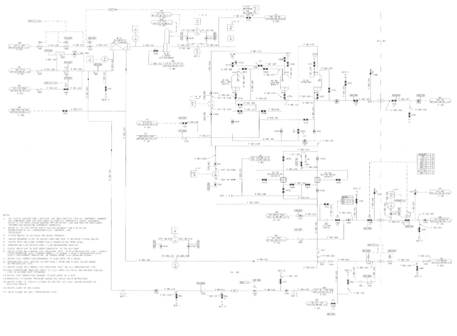
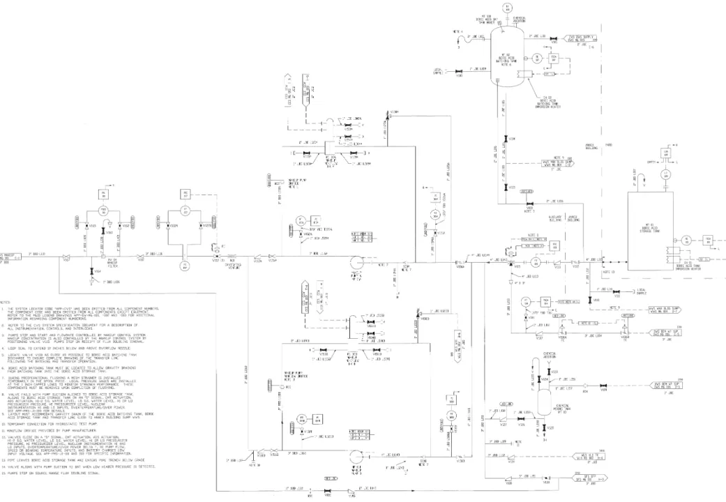
The chemical and volume control system consists of regenerative and letdown heat exchangers, demineralizers and filters, makeup pumps, tanks, and associated valves, piping, and instrumentation. The system parameters are given in Table 9.3.6-1. The piping and instrumentation diagram for the chemical and volume control system is included as Figure 9.3.6-1.
9.3.6.2.1 Purification 9.3.6.2.1.1 Ionic Purification
The normal chemical and volume control system purification loop is inside containment and operates at reactor coolant system pressure, utilizing the developed head of the reactor coolant pumps as the motive force for the purification flow. During power operations, fluid is continuously circulated through the chemical and volume control system from the discharge of one of the reactor coolant pumps. It passes through the regenerative heat exchanger where it is cooled by the returning chemical and volume control system flow, and is further cooled by component cooling water in the letdown heat exchanger to a temperature compatible with the demineralizer resins. The purification fluid flows through a mixed bed demineralizer, optionally through a cation bed demineralizer, and through a filter. It returns to the suction of a reactor coolant pump after being heated in the regenerative heat exchanger. The purification loop operates at reactor coolant system pressure.
Since the motive force for the purification loop is the reactor coolant pump head in a closed loop with the reactor coolant system, continuous purification is provided without operating the chemical and volume control system makeup pumps.
The mixed bed demineralizers are provided in the purification loop to remove ionic corrosion products and certain ionic fission products; they also remove zinc during periods of zinc addition. The demineralizers also act as filters. One mixed bed is normally in service, with a second demineralizer acting as backup in case the normal unit should become exhausted during operation.
9. Auxiliary Systems
AP1000 Design Control Document
Each demineralizer and filter is sized to provide a minimum of one fuel cycle of service without changeout.The mixed bed demineralizer in service can be supplemented by intermittent use of the cation bed demineralizer for additional purification in the event of fuel defects. In this case, the cation resin removes mostly lithium and cesium isotopes. The cation bed demineralizer has sufficient capacity to maintain the cesium-136 concentration in the reactor coolant below 1.0 microcurie per cubic centimeter with design basis fuel defects. Each mixed bed and the cation bed demineralizer is sized to accept the maximum purification flow. Filters are provided downstream of the demineralizers to collect particulates and resin fines.
During plant shutdowns when the reactor coolant pumps are stopped, the normal residual heat removal system provides the motive force for the chemical and volume control system purification. Purification flow from the normal residual heat removal system heat exchanger is routed directly through the normal chemical and volume control system purification loop. Boron changes and dissolved gas control are still possible by operating the chemical and volume control system in a semiclosed loop arrangement.
9.3.6.2.1.2 Gaseous Purification
Removal of radiogases from the reactor coolant system are not normally necessary because the gases do not build up to unacceptable levels when fuel defects are within normally anticipated ranges. If radiogas removal is required because of high fuel defects, the chemical and volume control system can be operated by routing flow to the liquid radwaste system degassifier. In this configuration, the letdown fluid is depressurized by flowing through the letdown orifice. The letdown flow is routed outside of containment through the liquid radwaste system degassifier to one of the liquid radwaste system effluent holdup tanks, and then returned to the reactor coolant system with the chemical and volume control system makeup pumps. This provides efficient gas removal.
Removal of radioactive gas and hydrogen during shutdown operations is necessary to avoid extending the maintenance and refueling outages. The reactor coolant system pressure boundary cannot be opened to the containment atmosphere until the gas concentrations are reduced to low levels. The shutdown degassing process is accomplished by operating the chemical and volume control system in the open loop configuration. In addition, a line is provided to allow the letdown orifice to be manually bypassed, so gas removal can continue after the reactor coolant system has been depressurized.
9.3.6.2.2 Reactor Coolant System Inventory Control and Makeup
Changes in reactor coolant volume are accommodated by the pressurizer level program for normal power changes, including transition from hot standby to full-power operation and returning to hot standby. In addition, the pressurizer has sufficient volume, within the deadband of the level control program, to accommodate minor reactor coolant system leakage for some time. The chemical and volume control system provides inventory control to accommodate minor leakage from the reactor coolant system, expansion during heatup from cold shutdown, and contraction
9. Auxiliary Systems
AP1000 Design Control Document
during cooldown. This inventory control is provided by letdown and makeup connections to the chemical and volume control system purification loop.9.3.6.2.3 Chemical Shim and Chemical Control
The chemical and volume control system provides the following functions to support the water chemistry and chemical shim requirements of the reactor coolant system:
• Means of addition and removal of pH control chemicals for startup and normal operation. • Means of addition and removal of soluble chemical neutron absorber (boron) and makeup
water, at concentrations and rates compatible with normal plant operation.
Reactor coolant system chemistry changes are accomplished with a feed and bleed operation. The letdown and makeup paths are operated simultaneously and appropriate chemicals are provided at the suction of the reactor makeup pumps.
9.3.6.2.3.1 Chemical Shim
Reactor coolant system boron changes are required to compensate for fuel depletion, startups, shutdowns, and refueling.
To borate the reactor coolant system, the operator sets the makeup control system to automatically add a preset amount of boric acid by fully diverting the three-way valve in the pump suction line to the boric acid storage tank, with delivered flow measured at the discharge of the makeup pumps. Dilution operates in a similar fashion. In either case, if the pressurizer level exceeds its control point, the letdown path to the liquid radwaste system holdup tanks is automatically opened.
Boric acid is provided to the boric acid storage tank by mixing 2.5 weight percent boric acid solution in the boric acid batching tank. Boric acid crystals are mixed with a mixer, while the mixture is heated to an appropriate temperature to provide efficient mixing by the batching tank immersion heater. After the boric acid crystals are dissolved, the solution is drained by gravity into the boric acid storage tank. No provisions are incorporated for boric acid recycle from the liquid radwaste system.
9.3.6.2.3.2 pH Control
The chemical agent used for pH control is lithium hydroxide (Li7OH). This chemical is chosen for its compatibility with the material and water chemistry of borated water, stainless steel, and zirconium systems. In addition, lithium-7 is produced in the core region because of irradiation of the dissolved boron in the coolant. A chemical mixing tank is provided to introduce the solution to the suction of the makeup pumps as required to maintain the proper concentration of Li7OH in the reactor coolant system.
The solution is poured into the chemical mixing tank and is then flushed to the suction manifold of the makeup pumps with demineralized water. A flow orifice is provided on the demineralized
9. Auxiliary Systems
AP1000 Design Control Document
water inlet pipe to allow chemicals to be flushed into the reactor coolant system at acceptable concentrations.The concentration of lithium-7 in the reactor coolant system varies according to a pH control curve as a function of the boric acid concentration of the reactor coolant system. If the concentration exceeds the proper value, as it may during the early stages of core life when lithium-7 is produced in the core at a relatively high rate, the cation bed demineralizer is used in the letdown path in series with the mixed bed demineralizer to lower the lithium-7 concentration. Since the buildup of lithium is slow, the cation bed demineralizer is used only intermittently. When letdown is being diverted to the liquid radwaste system, the purification flow is routed through the cation bed demineralizer for removal of as much lithium-7 and cesium as possible.
9.3.6.2.3.3 Zinc Addition
A soluble zinc compound may be added to the coolant as a means to reduce radiation fields within the primary system and to reduce the potential for crud-induced power shift (CIPS). The zinc used may be either natural zinc or zinc depleted of 64Zn.
9.3.6.2.4 Oxygen Control
The chemical and volume control system provides control of the reactor coolant system oxygen concentration, both during startup by introducing an oxygen scavenger and during power operations by driving toward zero the equilibrium concentration of oxygen produced by radiolysis in the core by injecting hydrogen.
9.3.6.2.4.1 Startups
During plant startup from cold conditions, an oxygen scavenging agent is used. The oxygen scavenger solution is introduced into the reactor coolant system via the makeup flow and chemical mixing tank, in the same manner as described for lithium-7 addition. The oxygen scavenger is used for oxygen control only at startup from cold shutdown conditions.
9.3.6.2.4.2 Power Operation
Dissolved hydrogen is employed during normal power operation to control and scavenge oxygen produced due to radiolysis of water in the core region. Hydrogen makeup is supplied to the reactor coolant system by direct injection of high-pressure gaseous hydrogen. The hydrogen comes from a bottle outside containment, through a containment penetration, and is mixed in the chemical and volume control system purification loop. Hydrogen removal from the reactor coolant system is not necessary because hydrogen is consumed in the core.
9.3.6.2.5 Reactor Coolant System Filling and Pressure Testing
Reactor coolant system filling is accomplished by using the chemical and volume control system makeup pumps to provide fluid a