Doctoral Dissertations Student Theses and Dissertations
Spring 2014
Turbo equalization for multiple-input multiple-output (MIMO)
Turbo equalization for multiple-input multiple-output (MIMO)
wireless communication systems
wireless communication systems
Longbao Wang
Follow this and additional works at: https://scholarsmine.mst.edu/doctoral_dissertations
Part of the Electrical and Computer Engineering Commons Department: Electrical and Computer Engineering
Department: Electrical and Computer Engineering Recommended Citation
Recommended Citation
Wang, Longbao, "Turbo equalization for multiple-input multiple-output (MIMO) wireless communication systems" (2014). Doctoral Dissertations. 2317.
https://scholarsmine.mst.edu/doctoral_dissertations/2317
This thesis is brought to you by Scholars' Mine, a service of the Missouri S&T Library and Learning Resources. This work is protected by U. S. Copyright Law. Unauthorized use including reproduction for redistribution requires the permission of the copyright holder. For more information, please contact [email protected].
COMMUNICATION SYSTEMS
by
LONGBAO WANG
A DISSERTATION
Presented to the Faculty of the Graduate School of the
MISSOURI UNIVERSITY OF SCIENCE AND TECHNOLOGY
In Partial Fulfillment of the Requirements for the Degree
DOCTOR OF PHILOSOPHY
in
ELECTRICAL ENGINEERING
2014
Approved by
Chengshan Xiao, Advisor Yiyu Shi
Kurt Kosbar Steve Grant Xiaoqing (Frank) Liu
PUBLICATION DISSERTATION OPTION
This dissertation consists of the following five published or submitted papers, formatted in the style used by the Missouri University of Science and Technology, listed as follows:
Paper I, L. Wang, J. Tao, C. Xiao and T. C. Yang, “Low-complexity turbo detection for single-carrier low-density parity-check-coded multiple-input multiple-output underwater acoustic communications,” has been published in Wireless Communications and Mobile Computing., vol. 13, pp 439-450, March 2013. (pages 8-36)
Paper II, L. Wang, J. Tao and Y. R. Zheng, “Frequency-Domain Turbo De-tection for No-CP Single-Carrier MIMO Underwater Acoustic Communications,” has been published in MTS/IEEE OCEANS, Kona, Hawaii, Sep. 2011. (pages 37-53)
Paper III, L. Wang, J. Tao and Y. R. Zheng, “Single-carrier frequency-domain turbo equalization without cyclic prefix or zero padding for underwater acoustic com-munications,” has been published in J. Acoustic Society of America , vol. 132, pp. 3809-3817, 2012. (pages 54-81)
Paper IV, J. Wu, L. Wang and C. Xiao, “Low Complexity Soft-Interference Cancelation Turbo Equalization for MIMO systems with Multilevel Modulations,” has been published in Proc. IEEE GLOBECOM, Atlanta, GA, Dec. 2013. (pages 82-102)
Paper V, J. Wu, L. Wang and C. Xiao, “Low Complexity Soft-Interference Cancelation Turbo Equalization for MIMO systems with Multilevel Modulations,” submitted to IEEE Trans. Veh. Technol., 2013. (pages 103-138)
ABSTRACT
This dissertation investigates both of the frequency domain and time domain
turbo equalization with multiple-input multiple-output (MIMO) fading channels for radio frequency and underwater acoustic communications. First, a low complexity
frequency domain turbo equalization (FDTE) is proposed for the MIMO systems with zero padding (ZP) or cyclic prefix (CP) inserted between the transmitted data blocks and its performance is tested on the real-world UWA communications experiments.
Second, as high speed communication system requires efficient bandwidth us-age and power consumption, CP or ZP is not transmitted as auxiliary information. An inter-block interference cancelation and CP reconstruction algorithm is developed
to re-arrange the channel matrix into a block diagonal one. This improvement makes the FDTE effectively detects the continuous data stream from the high speed UWA communications and its performance has been verified by processing data collected
from the UWA communications experiment.
Finally, a low complexity soft interference cancelation (SIC) time domain turbo equalizer for MIMO systems with high level modulation is proposed. Compared with
the conventional linear or nonlinear turbo equalizers, the proposed SIC turbo equalizer can theoretically reach the bound set up by the ideal match filter and its bit error rate (BER) performance from Monte Carlo simulation achieves a lower error floor as
ACKNOWLEDGMENTS
I would like first to express my deepest gratitude to my advisor, Dr. Changshan Xiao, for his encouragement, support and guidance through the journey of my PhD study. I thank him for inspiring me the interests of scientific research and encouraging and teaching me independent thinking.
Secondly, I would like to thank Dr. Yahong Rosa Zheng for being a valuable source of ideas and motivation as well. Dr. Yahong Rosa Zheng has provided helpful advices to me to overcome the difficulty both in my course work and my research.
I would also like to thank the members of my advisory committee, including Dr. Yiyu Shi, Steve Grant, Kurt Kosbar and Xiaoqing Liu. They have provided, with kindness, their insight and suggestions, which are precious to me.
In addition, I would like to acknowledge both Dr. Jun Tao and Dr. Jinxian Wu, co-authors of my publications, for their guidance and help in the achievement of the work.
I also want to express my sincere gratitude to past and present members in the research lab. I thank for their kindly support and friendship.
Finally I would like to express my eternal gratitude to my parents and parents-in-law for their everlasting love and support. I would also like to offer my extraordi-nary thanks to my wife, Fan(Ann) Ke, for her generous love, constant encouragement, and full support. I dedicate this dissertation to my 10-month baby, who is the joy of our lives.
TABLE OF CONTENTS
Page
PUBLICATION DISSERTATION OPTION . . . iii
ABSTRACT . . . iv
ACKNOWLEDGMENTS . . . v
LIST OF ILLUSTRATIONS . . . x
LIST OF TABLES . . . xii
SECTION 1 INTRODUCTION . . . 1
1.1 BACKGROUND AND PROBLEM STATEMENT . . . 1
1.2 PROBLEM STATEMENT . . . 3
1.3 SUMMARY OF CONTRIBUTIONS . . . 6
PAPER I. Low-Complexity Turbo Detection for Single-Carrier MIMO Underwater Acoustic Communications . . . 8
ABSTRACT . . . 8
1 INTRODUCTION . . . 9
2 SYSTEM MODEL . . . 12
3 LOW-COMPLEXITY TURBO DETECTION SCHEME . . . 14
3.1 SOFT-DECISION MIMO FDE . . . 14
3.2 SOFT-DECISION LDPC DECODER . . . 20
4 EXPERIMENTAL RESULTS . . . 21
4.1 RESULTS OF WHOI09 EXPERIMENT . . . 21
4.2 RESULTS OF ACOMM09 EXPERIMENT . . . 25
5 CONCLUSION . . . 33
II. Frequency Domain Turbo Equalization for No-CP Single-Carrier MIMO
Underwater Acoustic Communications . . . 37
ABSTRACT . . . 37
1 INTRODUCTION . . . 38
2 SYSTEM MODEL . . . 40
3 FREQUENCY-DOMAIN EQUALIZATION WITHOUT CP . . . 42
3.1 FIRST ITERATION . . . 42
3.2 SECOND ITERATION AND BEYOND . . . 45
3.3 LDPC DECODER . . . 46
4 EXPERIMENTAL RESULTS . . . 47
5 CONCLUSION . . . 52
6 REFERENCES . . . 53
III. Single-Carrier Frequency-Domain Turbo Equalization without Cyclic Prefix or Zero Padding for Underwater Acoustic Communications . . . 54
ABSTRACT . . . 54
1 INTRODUCTION . . . 55
2 SYSTEM DESCRIPTION . . . 58
3 PROPOSED LOW-COMPLEXITY TURBO DETECTION . . . 60
3.1 EQUALIZATION IN THE FIRST ITERATION . . . 61
3.2 EQUALIZATION IN THE SECOND ITERATION AND BEYOND 64 3.3 CHANNEL DECODING . . . 65
4 EXPERIMENTAL RESULTS . . . 66
5 CONCLUSION . . . 79
6 REFERENCES . . . 80
IV. Low Complexity Soft-Interference Cancelation Turbo Equalization for MIMO Systems with Multilevel Modulations . . . 82
ABSTRACT . . . 82
2 SYSTEM MODEL . . . 85
3 SOFT INTERFERENCE CANCELATION EQUALIZER . . . 87
3.1 SICE STRUCTURE . . . 87
3.2 FILTER DESIGN . . . 89
4 SOFT DECISIONS . . . 90
4.1 CALCULATIONS OF THE SOFT DECISIONS . . . 90
4.1.1 Anti-Causal Soft Decisions . . . 90
4.1.2 Causal Soft Decisions . . . 90
4.2 STATISTICAL PROPERTIES OF THE SOFT DECISIONS . . . 91
4.2.1 Conditional Moments of the Anti-Causal Soft Decisions ˜s(im) . . 93
4.2.2 Conditional Moments of the Causal Soft Decisions ˆs(im) . . . 93
5 SIMULATION RESULTS . . . 95
6 CONCLUSION . . . 99
7 PROOF OF PROPOSITION 1 . . . 100
8 PROOF OF COROLLARY 1 . . . 101
9 REFERENCES . . . 102
V. Low Complexity Soft-Interference Cancelation Turbo Equalization for MIMO Systems with Multilevel Modulations . . . 103
ABSTRACT . . . 103
1 INTRODUCTION . . . 104
2 SYSTEM MODEL . . . 108
3 SOFT INTERFERENCE CANCELATION EQUALIZER . . . 110
3.1 SICE STRUCTURE . . . 110
3.2 FILTER DESIGN . . . 112
4 SOFT DECISIONS . . . 116
4.1 CALCULATIONS OF THE SOFT DECISIONS . . . 116
4.1.1 Anti-causal Soft Decisions . . . 116
4.2 STATISTICAL PROPERTIES OF THE SOFT DECISIONS . . . 119
4.2.1 Conditional Moments of the Anti-causal Soft Decisions ˜s(im) . . 121
4.2.2 Conditional Moments of the Causal Soft Decisions ˆs(im) . . . 122
4.3 SPECIAL CASES . . . 123
4.3.1 η(k,jm) →0 and λ(k,jm) →0 . . . 123
4.3.2 η(k,jm) →0 and λ(k,jm) → ∞ . . . 123
4.3.3 η(k,jm) → ∞ and λ(k,jm) → ∞ . . . 123
5 CONVERGENCE ANALYSIS VIA EXIT CHART . . . 125
6 SIMULATION RESULTS . . . 131 7 CONCLUSIONS . . . 136 8 REFERENCES . . . 137 SECTION 2 CONCLUSIONS . . . 139 3 PUBLICATIONS . . . 140 REFERENCES . . . 141 VITA . . . 142
LIST OF ILLUSTRATIONS
Figure Page
PAPER I
2.1 Block diagram of the turbo detector. . . 13
4.1 Packet structure in WHOI09 experiment. . . 22
4.2 Correlation between the received signal and the local LFMb signal. . . 23
4.3 Estimated channels in WHOI09 experiment. . . 24
4.4 Demonstration of the turbo equalization process (16QAM) . . . 25
4.5 Estimated channels in ACOMM09 experiment. . . 27
PAPER II 2.1 Block diagram of the proposed turbo detection scheme. . . 40
3.1 Block partition in the first iteration. . . 44
4.1 Packet structure for ACOMM09. . . 48
4.2 Example of normalized LFMb correlation: (a). ACDS2, (b). ACDS3. . . . 48
4.3 Estimated MIMO channel (ACDS2). . . 49
4.4 Demonstration of turbo equalization process with 8PSK modulation: (a). ACDS2, (b). ACDS3. . . 50
PAPER III 1.1 Block diagram of the proposed turbo detection scheme. . . 56
3.1 Block partition in the first iteration. . . 63
4.1 Packet structure for ACOMM09. . . 66
4.2 Power spectrum of a received packet. . . 67
4.3 Examples of normalized LFMb correlations: (a). ACDS2, (b). ACDS3. . . 68
4.4 Estimated MIMO channel (ACDS2). . . 69
4.6 Demonstration of phase rotate estimation and compensation with 16QAM
modulation. . . 71
4.7 Demonstration of turbo equalization with 8PSK modulation (ACDS2). . . 72
4.8 Demonstration of turbo equalization with 8PSK modulation (ACDS3). . . 74
4.9 Demonstration of turbo equalization with 16QAM modulation (ACDS2). . 75
4.10Demonstration of turbo equalization with 16QAM modulation (ACDS3). . 76
PAPER IV 5.1 Average Projected EXIT chart for Tx2 with 8PSK Constellation and con-volution coding (SNR=18db) . . . 96
5.2 QPSK BER performance with convolutional coding. . . 97
5.3 8PSK BER performance with convolutional coding. . . 98
5.4 16QAM BER performance with convolutional coding. . . 98
PAPER V 1.1 Block diagram of the Transmitter and Receiver in MIMO channel model. . 107
3.1 Block diagram of the SICE receiver. . . 111
5.1 EXIT chart for Tx 2 with 8PSK constellation and convolutional code (SNR=18 dB). . . 129
5.2 Projected EXIT chart for Tx 2 with 8PSK constellation and convolutional code (SNR=18 dB). . . 129
5.3 Average projected EXIT chart for Tx 2 with 8PSK constellation and con-volutional code (SNR=18dB). . . 130
5.4 Average projected EXIT chart for Tx 2 with 16QAM Constellation and LDPC code (SNR = 20 dB). . . 130
6.1 QPSK BER performance with convolutional code. . . 132
6.2 8PSK BER performance with convolutional code. . . 133
6.3 16QAM BER performance with convolutional code. . . 133
6.4 QPSK BER performance with LDPC code. . . 134
6.5 8PSK BER performance with LDPC code. . . 134
LIST OF TABLES
Table Page
PAPER I
4.1 BER Results for 2×3 MIMO in WHOI09 experiment . . . 25
4.2 BER for 2×8 MIMO in ACOMM09 experiment (QPSK) . . . 28
4.3 BER for 2×8 MIMO in ACOMM09 experiment (8PSK) . . . 29
4.4 BER for 2×8 MIMO in ACOMM09 experiment (16QAM) . . . 30
4.5 BER for 2×4 MIMO in ACOMM09 experiment (QPSK) . . . 31
4.6 BER for 2×4 MIMO in ACOMM09 experiment (8PSK) . . . 31
4.7 BER for 2×4 MIMO in ACOMM09 experiment (16QAM) . . . 32
PAPER II 4.1 Detection Results for 2×8 MIMO . . . 51
PAPER III 4.1 Number of Error Bits for 2×8 MIMO with 16QAM Modulation . . . 73
4.2 Detection Results for 2×8 MIMO, Nb = 128 . . . 77
4.3 Detection Results for 2×8 MIMO, Nb = 256 . . . 77
4.4 Detection Results for 2×8 MIMO, Nb = 512 . . . 78
PAPER V 4.1 LLR simplifications for different constellations . . . 119
1.1 BACKGROUND AND PROBLEM STATEMENT
Increasing the transmission rate and reliability is always one of the basic ob-jects for the development of the wireless communication techniques. Recent studies have found that multiple-input multiple-output (MIMO) systems can achieve a signif-icant capacity gain [1] without additional power consumption at the transmitter side. The MIMO system deploys multiple antenna elements at both the transmitter and receiver sides so that the communication capacity grows linearly with the minimum number of transmit and receive antennas. This significant improvement can be ob-tained by spatial multiplexing and diversity coding, thus improving the transmission rate and reliability of the wireless communication system.
In practical wireless communication systems, the transmitted signal is usu-ally severely corrupted by the inter-symbol interference (ISI), which is introduced by the frequency selective fading wireless channels. For the MIMO systems, the trans-mit/receive antenna arrays also give rise to the reflection and scattering of the propa-gation radio wave, thus introducing other kind of interference whereas the single-input single-output (SISO) system does not have. Secondly, the time-varying nature or time selectivity, introduced by the relative movement of the transmitter and receiver, of the wireless channel can lead to Doppler shift, which imposes much difficulty on channel tracking. Also the carrier frequency offset (CFO), which is due to the mismatch of the local oscillator or instant Doppler shift, can degrade the performance of coherent receiver. Last, the co-channel interference (CCI) resulting uniquely from the mul-tiple paths between the antenna arrays or space selectivity can further increase the difficulty in transceiver design to achieve capacity gain as well as accurate detection.
To overcome the unreliability transmission over the frequency-selective, time-selective and space-time-selective channels in MIMO communication systems, forward error correction coding (channel coding) is used at the transmitter by adding redundant bits. And the redundancy enables the receiver to detect a limited number of bits and may correct them without retransmission. Then it is the task of receiver to detect the transmitted data sequence by exploiting the structure of the transmitted symbol constellation and the coding scheme. And functions of exploiting the structure of symbol constellation and coding scheme are considered as equalization and decoding. In a typical receiver, the equalizer first mitigates the ISI based on the channel state information. Utilizing the estimated transmitted symbols and the known cod-ing scheme, the decoder extracts the information and makes hard decisions of each transmitted bits. With the advantage of low computation complexity, the equalizer is usually designed as finite impulse response (FIR) filter, which is considered as linear equalizer (LE) [2, 3]. Also, the previous estimated symbols can be used to further mitigate the ISI and this is considered as decision feedback equalizer (DFE) [2, 3]. The derivation of the coefficients of the LE or DFE is based on different optimization criteria, such as zero forcing (ZF) or MMSE criteria. Optimal equalization for recov-ering the transmitted symbols is designed based on the maximum likelihood (ML) estimation, which turns into maximum a posterior probability (MAP) estimation in presence ofa prioriinformation about the transmitted data. We refer to this method as MAP/ML equalization. The output of the equalizer is passed to the decoder and the hard decision will be made to each transmitted bit within the method of conven-tional one-time equalization receiver. In order to further reduce the BER, a number of iterative receiver algorithms have been proposed to achieve the near-optimal per-formance by repeating the equalization and decoding operation on the same group of received data, using the feedback information from the decoder to implement the equalization. This iterative equalization is referred as turbo equalization and was first
introduced in [4]. With the increase of the reliability of the soft information by the iterative equalization and decoding, turbo equalization can achieve significant perfor-mance gains over one-time equalization [5, 6, 7]. All these operation are implemented in time domain.
On the other hand, even with linear processing in the equalization part, the receiver suffers from high computational complexity and slow convergence if the chan-nel length is long, because the complexity of the time domain equalization grows quadratically with the number of antenna elements and the number of channel taps. In high data-rate communication systems, the channel can span on the order of ten or even hundred of symbol duration. And underwater acoustic (UWA) channels impose more challenges than radio frequency environment with its excessive delay spread, frequency-dependent attenuation and significant time-varying Doppler shift. Hence frequency domain method has to be used to overcome this computational complex-ity. Orthogonal frequency division multiplexing (OFDM) and single carrier with fre-quency domain equalizer (SC-FDE) are considered as the two main frefre-quency domain methods for modern high data rate wireless communications. The major difference between these two methods is the replacement of the inverse fast Fourier transform (IFFT): IFFT is finished at transmitter in OFDM while at the receiver in SC-FDE.
1.2 PROBLEM STATEMENT
Specifically, this dissertation investigates technical challenges associated with frequency domain turbo equalization (FDTE) on and its practical applications on UWA MIMO communications. In the single-carrier (SC) MIMO communication sys-tems, the data bits after encoding are mapped into symbols based on the speci-fied modulation type. In some system, these modulated symbols will be grouped into blocks with cyclic prefix (CPs) or zero padding (ZPs) inserted between adjacent blocks. So that at the receiver, CPs are removed or overlap-add is performed with ZPs used in one block, and fast Fourier Transform (FFT) is calculated to convert the
time-domain signal to frequency domain. So that the equalization can be carried out on each frequency tone, and finally the equalized frequency domain signal is trans-formed to time domain with IFFT. Whereas in other systems, no CPs or ZPs are utilized in order to gain high spectrum usage. And this will introduce the inter-block interference which can be removed with CPs or ZPs employed.
1. How to extend the FDTE of SC SISO system to the MIMO system is the key step to utilize the FDTE to the real world data processing. In the UWA communication experiments, antenna array are deployed both at the transmitter and receiver. For SISO system, the system can be described asYk =HkXk+Nk,
where Xk and Yk are the scalar representing the kth frequency tone of the
transmitted/received signals respectively, and Hk is the kth frequency tone of
the frequency selective channel. While for the MIMO system, the superposition of signal from different transmitting antennas will make the received the signal in frequency domain the summation of the transmitted signal with corresponding weights being the channel responses at the same frequency tone. So how to exploit the transmission diversity of the MIMO system to separate the signals from different antennas within the FDTE methods is to be solved.
2. The appliance of the FDE method mostly requires the CPs or ZPs are inserted between adjacent blocks at the transmitter. In this way, the inter-block in-terference can be removed by cutting of the CPs segment at the receiver, or overlap-add operation with ZPs used. Either way will make the channel matrix in time domain representation into a circulant matrix and it can be transformed to a block diagonal matrix. So the system can be approximated as uncorrelated transmissions of different frequency tone signals, which can significantly reduce the detection complexity by using the FDE. However, the appended CPs or ZPs do not carry any useful information, thus bringing down the spectrum efficiency especially for the valuable available bandwidth for UWA communications. If
FDTE can be applied within the transmission system without adding CPs or ZPs, then we can improve the performance of detection without sacrificing the bandwidth to transmit auxiliary information.
3. FDTE is used to combat the ISI and CCI for the real world data received from the UWA communications employing the estimated channels. For MIMO archi-tecture, all the sub-channels corresponding to all transmitter and receiver pairs have to be estimated. Pilots were inserted in the transmitted symbol streams to assist the channel estimation. However for the rapid time-varying UWA chan-nels, channel tracking purely based on the inserted pilots is insufficient. How to effect and promptly track the channel is another important information before we process the data using FDTE.
The developed FDTE methods along with the channel estimation are applied to UWA communication systems. Underwater acoustic channels are characterized by excessive delay spread, frequency-dependent attenuation and significant time-varying Doppler shift. The attenuation of the sound wave traveling through water is propor-tional to the square of frequency, resulting in a much lower carrier frequency, smaller communication distance and narrower bandwidth to support the transmission than the RF system. In medium range UWA communication system, which means the transmission distance is between as 1 and 10 kilometers, the available bandwidth is on the level of several KHz. The dynamic movement of the water media leads to rapid time varying Doppler shift, and the ratio of Doppler shift to the carrier fre-quency is on the order of 10−4 to 10−3, much higher comparing with that of the RF
system which is on the order of 10−7 ∼ 10−9. These features of UWA channel make
it one of the worst physical links for communications and obtaining reliable MIMO UWA communications has been a challenging topic for decades. The proposed FDTE
methods and channel estimation are used at the receiver to achieve highly reliable UWA communications.
1.3 SUMMARY OF CONTRIBUTIONS
This dissertation consists of three journal publications and a couple of confer-ence papers as detailed in the publication list. My contributions that are published or under review are:
1. Low-Complexity Turbo Detection for Single-Carrier MIMO Underwater
Acoustic Communications: In the turbo equalization, the extrinsic information in the
form of log-likelihood ratio (LLR) is exchanged between the equalizer and decoder via interleaver or de-interleaver. And the calculation of the LLR is prohibitively complex if following the closed form expression. In this paper an approximation method is proposed to calculate the LLR from the equalizer, which significantly reduce the computation complexity especially for the high level modulation. The proposed FDTE is applied to process real-world data collected in two different undersea trials: WHOI09 and ACOMM09. The BER output of the FDTE decreases as the iteration increase and converges within only a few iterations. Experimental results show that the FDTE can achieve robust detection combining with the LDPC decoding scheme for MIMO UWA communication systems with different modulations and different symbol rate, at different transmission ranges.
2. Single-carrier frequency-domain turbo equalization without cyclic prefix or
zero padding for underwater acoustic communications: In order to achieve high
effi-cient spectrum usage for the UWA communications, no CPs or ZPs are inserted to split a continuous symbol stream into blocks. The received data stream is divided into consecutive blocks with size determined according to the channel condition. The inter-block-interference (IBI) cancelation and CP reconstruction are applied on each partitioned block, so that the channel matrix is block diagonalized in the frequency
domain and frequency-domain equalization can be operated for symbol detection at a very low complexity. The IBI is removed from the current block by using the estimated channel and the detected symbols from a previous block. The CP reconstruction is obtained by utilizing the soft symbol estimation from previous iteration. In the first iteration, the frequency-domain equalization is performed in an overlapped way with a bearable loss in detection efficiency and performance. Also during the processing of the real-world data, it shows that the constellation of the equalized symbols is rotated due to CFO. A novel and robust method is proposed to estimate the rotated phases and remove the phase bias for the equalized symbol. The experiment results of ACOMM09 has shown that the proposed FDTE can support high data-rate UWA communications with low bit error rate, even without CPs or ZPs inserted.
3. Low Complexity Soft-Interference cancellation Turbo Equalization for MIMO
Systems with Multilevel Modulations : Although the soft decision feedback turbo
equalization (SDFE) converges faster and has low SNR threshold, it cannot reach the bound of matched filter even after large number of iterations. By adding a anti-causal feedback filter to the SDFE structure, Soft-interference cancelation equalization can further remove the residual interference caused by the symbols transmitted after the symbol under detection. The performance of the proposed SICE is verified through both extrinsic information transfer chart (EXIT) analysis and computer simulations. The analytical and simulation results demonstrated that the inclusion of the anti-causal soft decision during SICE is critical to the system performance. The EXIT chart analysis indicates the SICE approaches the ideal matched filter bound as the iteration progresses.
PAPER
I. Low-Complexity Turbo Detection for Single-Carrier MIMO Underwater Acoustic Communications
Longbao Wang, Jun Tao, Chengshan Xiao Fellow, IEEE and T. C. Yang,
ABSTRACT—A low-complexity turbo detection scheme is proposed for
single-carrier multiple-input multiple-output (MIMO) underwater acoustic (UWA) commu-nications, which employ low-density parity-checking (LDPC) channel coding. The low complexity of the proposed detection algorithm is achieved in two aspects: first, the frequency-domain equalization technique is adopted, and it maintains a low com-plexity irrespective of the highly-dispersive UWA channels; second, the computation of the soft equalizer output, in the form of extrinsic log-likelihood ratio (LLR), is per-formed with an approximating method, which further reduces the complexity. More-over, attributed to the near-capacity LDPC decoding, the turbo detection converges within only a few iterations. The proposed turbo detection scheme has been used for processing real-world data collected in two different undersea trials: WHOI09 and ACOMM09. Experimental results show that it provides robust detection for MIMO UWA communications with different modulations and different symbol rates, at different transmission ranges.
Keywords: Turbo detection, frequency-domain equalization, underwater
1 INTRODUCTION
Underwater acoustic (UWA) communication is very challenging due to the severe condition of the UWA channel: first, the length of the equivalent discrete-time channel is extremely long due to the highly-dispersive channel impulse response (CIR); second, the time variation of the UWA channel is very fast due to the rapid dynamic variation of the oceans especially in shallow water; third, the Doppler effect of the underwater channel is significantly large due to the relatively low propagation speed of sound. Besides, the achievable transmission rate in UWA communications is usually low because of the limited available bandwidth.
Coherent detection using conventional equalization methods have been pro-posed in the literature [1]– [12]. With the advent of turbo equalization [6], [7], turbo detection for UWA communications is receiving more attention recently [6]– [9]. Com-pared with conventional one-time equalization, turbo equalization has a much more powerful detection capability, attributed to the iterative extrinsic soft information exchanges between a soft-decision equalizer and a soft-decision decoder. In [6], the soft-decision decision-feedback equalizer (DFE) together with the turbo decoder, has been applied to UWA communication. In [8], the turbo linear equalizer (LE) was proposed for long-term UWA communication testing. The convolutional decoder im-plemented with the classic BCJR algorithm [19], has been adopted. In [13], turbo detection using block decision-feedback equalization (BDFE) has also been proposed for single-carrier UWA communications. The BDFE leads to a better detection perfor-mance compared with the conventional DFE. Iterative decoding and turbo detection for orthogonal frequency-division multiplexing (OFDM) UWA systems has also been proposed in [11] and [9].
The equalization methods used in [6] and [8] are designed in the time domain, and the detection complexity increases with the channel length. On the other hand,
the equalization for OFDM systems [9] is performed in the frequency domain, and it has the advantage of low complexity. However, OFDM systems are very sensitive to the carrier frequency offset (CFO), thus it is very challenging to achieve reliable signal detection in UWA communication due to its significant Doppler effect. To avoid the drawback of OFDM while still achieve the advantage of low-complexity equalization, single-carrier frequency-domain equalizer (SC-FDE) has been proposed in [14] and [15].
In this paper, a low-complexity turbo detection scheme is proposed for single-carrier MIMO UWA communications using low-density parity-check (LDPC) channel coding. The proposed turbo detector has two main advantages. First, it has low equalization complexity even with the highly-dispersive UWA channels, by adopting the SC-FDE technique; Second, it has a fast convergence speed, which is enabled by the near-capability LDPC decoding [16]. The proposed detection scheme has been tested by extensive undersea trial data collected in two medium-range undersea experiments named WHOI09 and ACOMM09, respectively. The WHOI09 experiment was conducted at Buzzard’s Bay, MA, in December 2009. The transmission rate was 25 kilo-symbols per second (ksps) per transducer, at a transmission distance of 1∼2 km. The ACOMM09 experiment was launched at the coastline of New Jersey in May 2009, with a transmission rate of 5 ksps per transducer at a transmission distance of 2 ∼ 3 km. Experimental results show that in both experiments, error-free detection can be achieved for two-transducer MIMO transmissions with a QPSK modulation. With an 8PSK modulation, the WHOI09 experiment achieves a bit error rate (BER) in the order of 10−4, while error-free detection can still be achieved for
the ACOMM09 experiment. With a 16QAM modulation, the achievable BERs for the two experiments are in the order of 10−3 and 10−5, respectively.
The rest of this paper is organized as follows. In Section 2, the system model for a single-carrier MIMO UWA communication is described. The proposed low-complexity turbo detection scheme is presented in Section 3, and the experimental results are presented in Section 4. Finally, conclusions are drawn in Section 5.
Notations: Throughout this paper, (·)T and (·)H denote the transpose and
the Hermitian, respectively. E(·) and cov(·) represent the expectation and covariance operations. The Ij is an identity matrix of size j, and 0i×j denotes an i×j all-zero
matrix. A j ×j diagonal matrix with diagonal elements d1, d2,· · · , dj is represented
2 SYSTEM MODEL
Consider a MIMO UWA communication system with N transducers at the transmitter side and M hydrophones at the receiver side. On the m-th hydrophone, the baseband discrete-time samples can be represented as
ym,k = N X n=1 L−1 X l=0 hm,n(k, l)xn,k−l+vm,k (1)
where xn,k is the k-th transmitted symbol from the n-th transducer, hm,n(k, l) is the
l-th tap of the subchannel between the n-th transducer and the m-th hydrophone at time k, and vm,k is the zero-mean additive white Gaussian noise with power σ2. It
has been assumed that all subchannels have the same channel length,L.
Block transmission using zero padding [4], is adopted throughout this paper. When the time duration of one block is less than the UWA channel coherence time, the time-varying channel tap hm,n(k, l) can be treated as quasi-static within one
transmission block, and the model in (1) can be rewritten as
ym,k = N X n=1 L−1 X l=0 hm,n(l)xn,k−l+vm,k (2)
for k = 1,2,· · ·, Nb, Nb + 1,· · · , Nb +Ng, where Nb and Ng are the block size and
the zero-padding size, respectively. To avoid inter-block interference, Ng ≥L−1 has
Soft−decision MIMO FDE
Soft−decision Decoded info. bits
Rx Blocks Doppler LDPC decoder Channel Estimator Preprocessor y L(c) Le(c) Le(b) Ld e(b) Ld e(c) ˆ h Ld(b) Π−1 Π
3 LOW-COMPLEXITY TURBO DETECTION SCHEME
The structure of the proposed turbo detection scheme is shown in Fig. 1.1, where the received signal is first passed through a Doppler preprocessing unit to remove any motion-induced Doppler effect [12]. The preprocessed signal is sent to the soft-decision MIMO FDE and the channel estimator unit. The channel estima-tor performs minimum mean square error (MMSE) channel estimation in the time domain. Details are referred to [13]. With the estimated channel knowledge, the frequency-domain equalization can be performed and the turbo detection is launched by exchanging extrinsic log-likelihood ratio (LLR) information between the FDE and the LDPC decoder in an iterative way, via the interleaver (Π) and de-interleaver (Π−1). Within each iteration of the detection, the LDPC decoder performs multiple
iterations for the decoding. In the rest of the paper, we call the iteration of detection as “detection iteration”, and the iteration of LDPC decoding as “decoding iteration”, respectively. Once the turbo detection converges, the LDPC decoder will output the hard decisions on the information bits. In the following two subsections, the soft-decision MIMO FDE and the soft-soft-decision LDPC decoder are discussed, respectively.
3.1 SOFT-DECISION MIMO FDE
Define xk = [x1,k,· · · , xN,k]T, yk = [y1,k,· · · , yM,k]T, vk = [v1,k,· · · , vM,k]T as
the transmitted symbol vector, the received sample vector, and the noise vector at time k, respectively. A whole block of received samples can then be denoted as
Performing the overlap-add operation as follows y = [yT1,· · · ,yLT−1,yTL,· · · ,yTN b] T + [yTN b+1,· · · ,y T Nb+L−1,0 T M×1,· · ·,0TM×1]T (4) we have y=Htdx+v (5) where x= [xT1,xT2,· · · ,xTN b] T and Htd = h0 0 · · · 0 hL−1 hL−2 · · · h1 h1 h0 0 · · · 0 hL−1 · · · h2 ... . .. ... ... ... ... ... ... hL−1 hL−2 · · · h0 0 0 · · · 0 0 hL−1 · · · h1 h0 0 · · · 0 ... . .. ... ... ... ... ... ... 0 · · · 0 0 hL−1 hL−2 · · · h0 (6) with hl given as hl = h1,1(l) · · · h1,N(l) h2,1(l) · · · h2,N(l) ... . .. ... hM,1(l) · · · hM,N(l) (7)
The subscripts of the all-zero matrices 0M×N in (6) has been omitted for brevity.
Finally, the noise vector v is defined similar to y in (4). Due to the overlap-add operation, the variances of the first M(L−1) samples in the noise vector v become
twice of those of other samples. For the convenience of mathematical analysis, we have assumed all samples invhave the same varianceσ2. In the real data processing,
the difference in noise variances has been considered.
To perform frequency-domain equalization, the time-domain signals x and y
need to be transformed into the frequency domain. Define two transform matrices
Fx = Fx(1,1) · · · Fx(Nb,1) Fx(1,2) · · · Fx(Nb,2) .. . . .. ... Fx(1, Nb) · · · Fx(Nb, Nb) (8) Fy = Fy(1,1) · · · Fy(Nb,1) Fy(1,2) · · · Fy(Nb,2) ... . .. ... Fy(1, Nb) · · · Fy(Nb, Nb) (9) where Fx(l, p) = W l,p NbIN and Fy(l, p) =W l,p NbIM, with W l,p Nb = 1 √ Nbexp(− j2π(l−1)(p−1) Nb )
for l, p= 1,2,· · · , Nb. Applying Fy on both sides of (5), leads to
Y = FyHtdFHx Fxx+Fyv
= HX+V (10)
where Y=Fyy, X=Fxx, V=Fyv, and
H = FyHtdFHx
The submatrixHk has the following form Hk= H1,1(k) . . . H1,N(k) .. . . .. ... HM,1(k) . . . HM,N(k) (12) with Hm,n(k) = PL−1 l=0 hm,n(l)exp(−j2πlN(k−1) b ).
The system model in (10) can be decomposed into Nb parallel subsystems as
follows
Yk=HkXk+Vk (k = 1,2,· · · , Nb) (13)
whereXk= [X1,k, X2,k, . . . , XN,k]T,Yk = [Y1,k, Y2,k, . . . , YM,k]T, andVk= [V1,k, V2,k, . . . ,
VM,k]T are subvectors extracted from X,Y and V, respectively.
For the k-th subsystem, the linear minimum mean square error (LMMSE) estimation of Xk is given as
ˆ
Xk=AHk(Yk−HkX¯k) + ¯Xk (14)
whereAH
k is the equalizer matrix, and ¯Xk is thea priori mean ofXk. The
computa-tion ofAH
k and ¯Xkrequires the symbol a priorimean and variance, which are defined
as follows ¯ xn,k = X α∈S α·P(xn,k =α) (15) ̺2n,k = X α∈S |α−x¯n,k|2P(xn,k =α) (16)
whereS is the constellation set of size 2Q. The probability, P(x
n,k =α), is calculated
from thea priori LLRs,{La(cjn,k)} Q j=1, of xn,k’s demapping bits, {cjn,k} Q j=1, as follows P(xn,k =α) = Q Y j=1 1 +sj·tanh(La(c j n,k)) 2 (17) where sj = +1; aj = 0 −1; aj = 1 with{aj}Q
j=1being the demapping bits of the symbolα. The function tanh(x) denotes
hyperbolic tangent. The a priori LLR,La(c j
n,k), at the input of the FDE is equal to,
Ld e(c
j
n,k), as shown in Fig. 1.1. In the first detection iteration, there is no a priori
information available thus the bit LLR is set as La(cjn,k) = 0.
Let ¯x = [¯x1,1,· · · ,x¯N,1,· · · ,x¯1,Nb,· · · ,x¯N,Nb]
T
, then we have ¯X = Fxx¯ from
which ¯Xk can be extracted. The equalizer matrix Ak is solved as
Ak = cov(Yk,Yk)−1cov(Yk,Xk) = (HkΨH¯ Hk +σ2IM)−1HkΨ¯ (18) where ¯Ψ= diag{̺¯2 1,· · · ,̺¯2N} with ¯̺2n= N1b PNb k=1̺2n,k.
The computation of the equalizer matrixAk in (18) only requires the inversion
of a small square matrix of size M. For the Nb subsystems, the incurred complexity
is in the order ofO(NbM3). Obviously, the overall complexity only increases linearly
in Nb, thus is low. It is noted that the low-complexity operation of the FDE is
independent of the channel length L, whereas the time-domain equalization (TDE) methods [6,8] have their complexity increase in the cubic ofL. For a highly-dispersive UWA channel, the value ofL amounts to several tens or even over one hundred, and
the complexity of the time-domain equalization will get very high. Therefore, the FDE is a better choice than the TDE from the point view of complexity, especially for UWA communications.
With the estimated frequency-domain symbols,{Xˆk}Nk=1b , of allNb subsystems,
the time-domain symbol estimations, ˆx, can be obtained as
ˆ
x = FHx Xˆ (19)
where ˆX= [ ˆX1,Xˆ2,· · · ,XˆNb]
T. In conventional one-time equalization, symbol
detec-tion will be made based on the estimated vector ˆx. In turbo equalization, instead, the extrinsic bit LLRs will be calculated based on ˆx. For the estimated symbol ˆxn,k,
the extrinsic LLR of its j-th demapping bit is evaluated as follows [17]
Le(cjn,k|xˆn,k) = ln P ∀α∈S,aj=0p(ˆxn,k|xn,k =α) Q j′6=j P(cjn,k′ =aj′ ) P ∀α∈S,aj=1p(ˆxn,k|xn,k =α)Q j′6=j P(cjn,k′ =aj′ ) (20)
According to (8), the conditional probability density function (PDF)p(ˆxn,k|xn,k =α)
needs to be determined. By using the common assumption of Gaussian distribution [17], the determination of the PDF is equivalent to fining the conditional mean, µn,k ,E{xˆn,k|xn,k =α}, and the conditional variance,η2n,k ,cov(ˆxn,k,ˆxn,k|xn,k =α).
The computation of the conditional mean and variance requires extra com-plexity. During the undersea data processing, however, we adopt an approximate approach for computing µn,k and ηn,k2 to further reduce the detection complexity.
The approximating method is based on the fact that an estimated symbol ˆxn,k can
be written as follows
ˆ
wherexn,k is the actually transmitted symbol, ρis a scale factor, andζ is the additive
estimation noise. Based on (21), the parameter ρ is first estimated as
ˆ ρ= v u u t 1 Nb Nb X k=1 |xˆn,k|2 |x˘n,k|2 (22)
where ˘xn,k denotes the hard decision of ˆxn,k. The conditional mean and variance can
then be approximately computed as
µn,k ≈ ραˆ (23) ηn,k2 ≈ E{ζ2}≈ PNb k=1(|xˆn,k−µn,k|2) Nb (24)
Once µn,k and ηn,k2 are determined, the conditional PDF p(ˆxn,k|xn,k = α) and the
extrinsic bit LLR Le(cjn,k|xˆn,k) are obtained. The extrinsic bit LLRs of the FDE will
then be de-interleaved and delivered to the LDPC decoder for decoding.
3.2 SOFT-DECISION LDPC DECODER
The Column-Weight-Three binary LDPC codes [18], [19] with code word length 2048, 3072 and 4096 have been adopted in both experiments. The code rate is 12. The LDPC decoding has been extensively studied in the literature, and we adopt the sum-product algorithm proposed in [10]. Details are omitted for brevity.
The extrinsic LLR generated by the LDPC decoder will be interleaved and fed back to the FDE for launching the next iteration of the turbo equalization. When the turbo detection converges, the LDPC decoder outputs the hard decisions of the information bits and this completes the turbo detection.
4 EXPERIMENTAL RESULTS
The proposed low-complexity turbo detector has been tested by real-world data collected in two undersea experiments. The first experiment named WHOI09, was conducted at Buzzard’s Bay, MA, in December 2009. The second experiment named ACOMM09, was launched at the coastline of New Jersey in May 2009. Results for the two experiments are presented in the following two subsections, respectively.
4.1 RESULTS OF WHOI09 EXPERIMENT
In this experiment, the symbol period was 0.04 ms and the carrier frequency was 32.5 kHz. Modulation schemes included QPSK, 8PSK and 16QAM, resulting transmission rates of 50 kilo-bits per second (kbps), 75 kbps, and 100 kbps, respec-tively, for a single transducer. The transmit equipment, consisting of two transducers, was located about 6 m below the sea surface. The water depth was about 14 m. Two receive hydrophone arrays named R1 and R2 were deployed, and their distances to the transmitter were 2 km and 1 km, respectively. Each receive array consisted of four hydrophones.
The zero-padded blocks were organized into packets for transmission during the experiment, with the packet structure shown in Fig. 4.1. From the figure,
auxiliary signal including two linear frequency modulation (LFM) sequences named LFMb and LFMe, and one m-sequence, are also transmitted. The LFM sequences serve multiple purposes like packet coarse synchronization, Doppler shift estimation, and channel length measurement. Them-sequence can be used to evaluate the channel scattering function. Details are referred to [12]. The data payload consists of multiple blocks separated by padded zeros. The zero-padding length has been chosen asNg =
300 to avoid inter-block interference under highly-dispersive UWA channels. Each block containsNb modulation symbols, out of which the Np ones at the head are used
Data payload
m_seq
LFMb gap gap LFMe
Np Nd Np Nd Ng Time Nb Nd Np Np Nd
Figure 4.1. Packet structure in WHOI09 experiment.
as pilots for channel estimation and the remaining Nd = Nb −Np symbols convey
information. The block size Nb has three choices: 1024, 2048 and 4096. For a given
packet, the block size Nb is fixed while the three modulations are all used. For a
given block, it carries one or more LDPC code words depending on the modulation adopted.
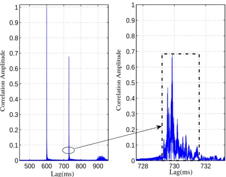
In Fig. 4.2, an example of the normalized correlation between the received sig-nal and the local LFMb sigsig-nal is demonstrated. In the left subfigure, two correlation peaks are observed due to the two-transducer transmission. Either peak indicates the coarse synchronization point. To measure the length of the practical channel, the right correlation ridge in the left subfigure, is zoomed in in the right subfigure. From the subfigure, it is obvious that most of the correlation energy is concentrated inside a time window of size about 2.4 ms, which corresponds to a symbol-spaced channel length of L= 60. For such a channel length, the pilot length is chosen as Np = 220.
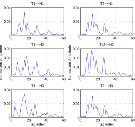
An example of the estimated UWA channels between the transmit array and the receive array R2 is illustrated in Fig. 4.3, where ‘T’ and ‘H’ denote transducer and hydrophone, respectively. The subchannels corresponding to the fourth hydrophone are not shown because during the data processing, it was found that hydrophone failed to function. The same problem happened with R1, thus the detection has been
performed with the three normal hydrophones for both R1 and R2. From the figure, the channel impulse responses are non-minimum phase.
500 600 700 800 900 0 0.1 0.2 0.3 0.4 0.5 0.6 0.7 0.8 0.9 1 Lag(ms) Correlation Amplitude 728 730 732 0 0.1 0.2 0.3 0.4 0.5 0.6 0.7 0.8 0.9 1 Lag(ms) Correlation Amplitude
Figure 4.2. Correlation between the received signal and the local LFMb signal.
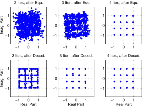
With the estimated channel knowledge, turbo equalization can be performed. To demonstrate the progress of equalization, Fig. 4.4 shows the estimated symbols at the output of the FDE and the soft-decision symbols at the output of the LDPC decoder, respectively, over multiple iterations. The modulation is 16QAM. From the figure, the performance improvement attributed to the iterative operations is intuitively observed.
Detection results for this experiment are next presented. Five packets have been detected for both R1 and R2. Each packet contains twelve Nb = 1024 blocks
for each of the three modulations QPSK, 8PSK and 16QAM. The number of LDPC decoding iterations has been fixed as 15. The detection performance metric is chosen
0 20 40 60 0 0.02 0.04 T1−−H1 0 20 40 60 0 0.02 0.04 T2−−H1 0 20 40 60 0 0.01 0.02 0.03 Normalized Amplitude T1−−H2 0 20 40 60 0 0.01 0.02 0.03 Normalized Amplitude Tx2−−H2 0 20 40 60 0 0.02 0.04 tap index T1−−H3 0 20 40 60 0 0.02 0.04 tap index T2−−H3
Figure 4.3. Estimated channels in WHOI09 experiment.
as the bit error rate (BER), which is defined as the ratio between the total number of error bits and the total number of information bits. The BERs are listed in Table 4.1, where Ndet denotes the number of detection iterations.
From the table, it is obvious that error-free detection has been achieved for QPSK modulation with only two detection iterations. The BERs for the 8PSK and 16QAM modulations are in the order of 10−4 and 10−3 on both hydrophone arrays,
with four detection iterations. It is expected that better performance can be achieved if all four hydrophones are used for detection.
−1 0 1 −1
0 1
Imag. Part
2 Iter., after Equ.
−1 0 1
−1 0 1
3 Iter., after Equ.
−1 0 1
−1 0 1
4 Iter., after Equ.
−1 0 1 −1 0 1 Real Part Imag. Part
2 Iter., after Decod.
−1 0 1
−1 0 1
Real Part 3 Iter., after Decod.
−1 0 1
−1 0 1
Real Part 4 Iter., after Decod.
Figure 4.4. Demonstration of the turbo equalization process (16QAM)
Table 4.1. BER Results for 2×3 MIMO in WHOI09 experiment
P P P P P P P PP Mod. Ndet 1 2 3 4 R1 QPSK 2.3×10⁻⁴ 0 0 0 8PSK 1.5×10⁻² 2.8×10⁻⁴ 9.8×10⁻⁵ 9.8×10⁻⁵ 16QAM 5.8×10⁻² 4.2×10⁻³ 2.0×10⁻³ 1.9×10⁻³ R2 QPSK 2.1×10⁻⁴ 0 0 0 8PSK 1.3×10⁻² 2.1×10⁻⁴ 8.1×10⁻⁵ 8.1×10⁻⁵ 16QAM 5.3×10⁻² 4.1×10⁻³ 1.2×10⁻³ 1.1×10⁻³
4.2 RESULTS OF ACOMM09 EXPERIMENT
In this experiment, the symbol period was 0.2 ms and the carrier frequency was 17 kHz. Three modulation schemes including QPSK, 8PSK and 16QAM, were used.
The transmit equipment was a four-transducer array, for which the number of active transducers was flexibly configured to implement different MIMO transmission during the experiment. Two hydrophone arrays named ACDS2 and ACDS3 were deployed, and each of them consisted of eight elements. The inter-hydrophone spacing was 2.06 m on both arrays. The distances between ACDS2 and ACDS3 to the transmit equipment were 2 km and 3 km, respectively.
The data blocks were again encapsulated into packets for transmission, sim-ilar to the WHOI09 experiment. The block size had two choices: Nb = 1024 and
Nb = 2048, and each block carried one or more LDPC code words. Different from
the WHOI09 experiment, each packet only used one instead of all three modulation schemes.
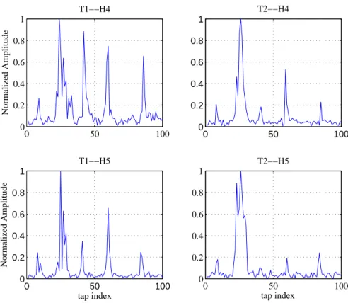
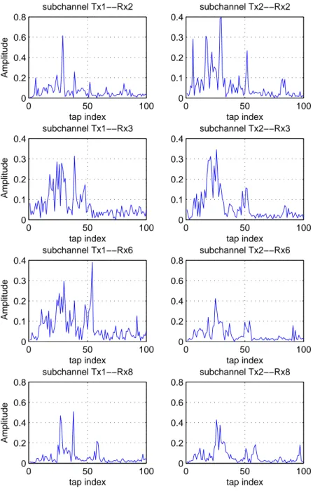
The channel length was measured asL= 100 in this trial, and the pilot block length was selected asNp = 350. In Fig. 4.5, the estimated undersea channels between
the transmit array and the receive array ACDS2 are demonstrated. Clearly, the CIRs are non-minimum phase and sparse, and have several distinct spikes.
Four packets have been detected for each of the three modulations, for both ACDS2 and ACDS3. Each packet contains 50 blocks with a block size Nb = 1024.
The detection results of the two-transducer transmission, are shown in Table 4.2 through Table 4.4 for the three different modulations. The parameter Ndec in all
tables denotes the number of LDPC decoding iterations. From the tables, the BER results corresponding to different combinations of detection iteration number, Ndet,
and decoding iteration number, Ndec, have been provided for comparison. We make
the following observations for the results. First, for a fixed number of detection iterations, Ndet, the system performance increases with the number of decoding
iter-ations, Ndec. Similarly, when the number of decoding iterations, Ndec, is fixed, the
performance improves with the number of detection iterations, Ndet, as we already
0 50 100 0 0.2 0.4 0.6 0.8 1 Normalized Amplitude T1−−H4 0 50 100 0 0.2 0.4 0.6 0.8 1 T2−−H4 0 50 100 0 0.2 0.4 0.6 0.8 1 tap index Normalized Amplitude T1−−H5 0 50 100 0 0.2 0.4 0.6 0.8 1 tap index T2−−H5
Figure 4.5. Estimated channels in ACOMM09 experiment.
detection has been achieved on both ACDS2 and ACDS3. As expected, the 8PSK modulation requires more iterations than the QPSK modulation to reach zero BER. Third, in Table 4.4, performance bound has been observed for ACDS3. Particularly, when (Ndet, Ndec) = (2,7), the BER stops decreasing even both iteration numbers
are increasing. This phenomena is explained by the convergence behavior of turbo detection [21]. This observation provides us the hint to select a proper combination of (Ndet, Ndec), which leads to the best performance-complexity tradeoff. Last, with
a 16QAM modulation, a BER on the order of 10−5 can be achieved for both ACDS2
Table 4.2. BER for 2×8 MIMO in ACOMM09 experiment (QPSK) ACDS2 H H H H H H Ndet Ndec 1 2 3 1 1.8×10⁻⁴ 0 0 2 4.8×10⁻⁵ 0 0 3 4.0×10⁻⁵ 0 0 4 3.9×10⁻⁵ 0 0 ACDS3 1 3.7×10 −6 0 0 2 0 0 0
For the results shown in Table 4.2 through Table 4.4, all eight hydrophone elements have been used for detection. Attributed to the spatial diversity provided by all eight hydrophones, the turbo detection converges very fast. For example, in Table 4.2, perfect detection can be achieved with only one detection iteration and two decoding iterations. More hydrophones provides more diversity gain, however, also incurs higher detection complexity. As a result, hydrophone selection becomes another degree of freedom to balance the performance-complexity tradeoff. To demonstrate that, we re-detect all the packets by using only four hydrophones with indices 1,3,5,7. The new results are given through Table 4.5 to Table 4.7. From Table 4.5, the detection performance for ACDS3 almost does not degrade compared with that in Table 4.2. For ACDS2, performance degradation is observed by comparing with Table 4.2. However, perfect detection can still be achieved with only one detection iteration when the number of decoding iteration increases to 9. For 8PSK and 16QAM modulations, the results for both ACDS2 and ACDS3 degrade compared with those
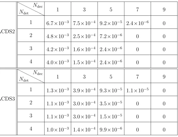
Table 4.3. BER for 2×8 MIMO in ACOMM09 experiment (8PSK) ACDS2 H H H H H H Ndet Ndec 1 3 5 7 9 1 6.7×10⁻³ 7.5×10⁻⁴ 9.2×10⁻⁵ 2.4×10⁻⁶ 0 2 4.8×10⁻³ 2.5×10⁻⁴ 7.2×10⁻⁶ 0 0 3 4.2×10⁻³ 1.6×10⁻⁴ 2.4×10⁻⁶ 0 0 4 4.0×10⁻³ 1.5×10⁻⁴ 2.4×10⁻⁶ 0 0 ACDS3 H H H H H H Ndet Ndec 1 3 5 7 9 1 1.3×10⁻³ 3.9×10⁻⁴ 9.3×10⁻⁵ 1.1×10⁻⁵ 0 2 1.1×10⁻³ 3.0×10⁻⁴ 3.5×10⁻⁵ 0 0 3 1.1×10⁻³ 3.0×10⁻⁴ 1.5×10⁻⁵ 0 0 4 1.0×10⁻³ 1.4×10⁻⁴ 9.9×10⁻⁶ 0 0
obtained using all eight hydrophones. Nevertheless, the achievable BERs on the order of 10−5 and 10−4 are still satisfactory.
Finally, we briefly discussed the signal detection for MIMO transmission with more than two transducers. Due to the increased number of transducers, the pilot block size Np has to be enlarged so as to achieve accurate channel estimations. The
resulting pilot overhead will be very large for each transmission block. To maintain an acceptable pilot percentage, we have adopted a different channel estimation scheme. In the new scheme, transmission blocks within a packet are classified into two cat-egories: pilot blocks and information blocks. The pilot blocks are used specifically for channel estimation, while the detected information blocks are used for channel tracking. For example, we select blocks with indices 1, 11, 21, 31 and 41 as pilot blocks for channel estimation, and use each detected information block to re-estimate
Table 4.4. BER for 2×8 MIMO in ACOMM09 experiment (16QAM) ACDS2 H H H H H H Ndet Ndec 3 5 7 9 11 1 4.4×10⁻³ 1.4×10⁻³ 4.6×10⁻⁴ 1.2×10⁻⁴ 3.3×10⁻⁵ 2 3.0×10⁻³ 7.3×10⁻⁴ 1.4×10⁻⁴ 1.6×10⁻⁵ 1.5×10⁻⁵ 3 2.7×10⁻³ 5.6×10⁻⁴ 1.0×10⁻⁴ 1.6×10⁻⁵ 1.3×10⁻⁵ 4 2.6×10⁻³ 5.4×10⁻⁴ 1.0×10⁻⁴ 1.6×10⁻⁵ 1.3×10⁻⁵ ACDS3 H H H H H H Ndet Ndec 1 3 5 7 9 1 3.8×10⁻³ 5.4×10⁻⁴ 6.4×10⁻⁵ 1.2×10⁻⁵ 1.2×10⁻⁵ 2 2.9×10⁻³ 2.4×10⁻⁴ 1.5×10⁻⁵ 1.0×10⁻⁵ 1.0×10⁻⁵ 3 2.6×10⁻³ 1.2×10⁻⁴ 1.2×10⁻⁵ 1.0×10⁻⁵ 1.0×10⁻⁵ 4 2.6×10⁻³ 1.2×10⁻⁴ 1.1×10⁻⁵ 1.0×10⁻⁵ 1.0×10⁻⁵
the channel for detecting the next adjacent information block. In this case, only 5 out of 50 blocks are used as pilot blocks and the pilot overhead is only 10%. With the modified channel estimation mechanism, perfect detection has been achieved with some QPSK packets measured under 4×8 MIMO transmission. As to 8PSK and 16QAM modulations, the detection becomes much more challenging due to the error propagation in the decision-directed channel tracking. To provide an effective channel tracking in the case of high modulations, will be the focus of our future work.
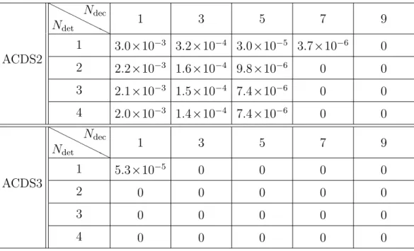
Table 4.5. BER for 2×4 MIMO in ACOMM09 experiment (QPSK) ACDS2 H H H H H H Ndet Ndec 1 3 5 7 9 1 3.0×10⁻³ 3.2×10⁻⁴ 3.0×10⁻⁵ 3.7×10⁻⁶ 0 2 2.2×10⁻³ 1.6×10⁻⁴ 9.8×10⁻⁶ 0 0 3 2.1×10⁻³ 1.5×10⁻⁴ 7.4×10⁻⁶ 0 0 4 2.0×10⁻³ 1.4×10⁻⁴ 7.4×10⁻⁶ 0 0 ACDS3 H H H H H H Ndet Ndec 1 3 5 7 9 1 5.3×10⁻⁵ 0 0 0 0 2 0 0 0 0 0 3 0 0 0 0 0 4 0 0 0 0 0
Table 4.6. BER for 2×4 MIMO in ACOMM09 experiment (8PSK)
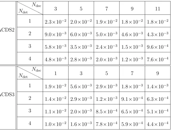
ACDS2 H H H H H H Ndet Ndec 1 3 5 7 9 1 8.0×10⁻³ 6.9×10⁻⁴ 3.5×10⁻⁴ 2.3×10⁻⁴ 2.0×10⁻⁴ 2 7.4×10⁻³ 5.3×10⁻⁴ 2.6×10⁻⁴ 1.3×10⁻⁴ 1.2×10⁻⁴ 3 7.1×10⁻³ 4.8×10⁻⁴ 2.1×10⁻⁴ 1.0×10⁻⁴ 3.8×10⁻⁵ 4 6.7×10⁻³ 4.3×10⁻⁴ 1.7×10⁻⁴ 8.8×10⁻⁵ 2.9×10⁻⁵ ACDS3 H H H H H H Ndet Ndec 1 3 5 7 9 1 1.5×10⁻³ 6.1×10⁻⁴ 2.9×10⁻⁴ 2.1×10⁻⁴ 1.8×10⁻⁴ 2 1.4×10⁻³ 4.6×10⁻⁴ 2.1×10⁻⁴ 1.2×10⁻⁴ 1.1×10⁻⁴ 3 1.4×10⁻³ 4.1×10⁻⁴ 1.8×10⁻⁴ 8.8×10⁻⁵ 2.9×10⁻⁵ 4 1.3×10⁻³ 4.0×10⁻⁴ 1.6×10⁻⁴ 6.8×10⁻⁵ 1.7×10⁻⁵
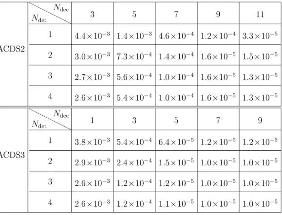
Table 4.7. BER for 2×4 MIMO in ACOMM09 experiment (16QAM) ACDS2 H H H H H H Ndet Ndec 3 5 7 9 11 1 2.3×10⁻² 2.0×10⁻² 1.9×10⁻² 1.8×10⁻² 1.8×10⁻² 2 9.0×10⁻³ 6.0×10⁻³ 5.0×10⁻³ 4.6×10⁻³ 4.3×10⁻³ 3 5.8×10⁻³ 3.5×10⁻³ 2.4×10⁻³ 1.5×10⁻³ 9.6×10⁻⁴ 4 4.8×10⁻³ 2.8×10⁻³ 2.0×10⁻³ 1.2×10⁻³ 7.6×10⁻⁴ ACDS3 H H H H H H Ndet Ndec 1 3 5 7 9 1 1.9×10⁻² 5.6×10⁻³ 2.9×10⁻³ 1.8×10⁻³ 1.4×10⁻³ 2 1.4×10⁻² 2.9×10⁻³ 1.2×10⁻³ 9.1×10⁻⁴ 6.3×10⁻⁴ 3 1.1×10⁻² 2.0×10⁻³ 8.5×10⁻⁴ 6.5×10⁻⁴ 5.1×10⁻⁴ 4 1.0×10⁻² 1.6×10⁻³ 7.8×10⁻⁴ 5.9×10⁻⁴ 4.4×10⁻⁴
5 CONCLUSION
A low-complexity turbo detection scheme was proposed for single-carrier LDPC-coded MIMO UWA communications. The new detector achieved the low-complexity advantage by using the frequency-domain equalization technology combined with the computationally-efficient LDPC decoding. The performance of the proposed detection scheme was tested by real-world data measured in the WHOI09 undersea experiment and the ACOMM09 undersea experiment. With QPSK modulation, it was shown that error-free detection could be achieved under two-transducer transmission for both ex-periments. With 8PSK modulation, the achievable BERs were in the order of 10−4
at a symbol rate of 25 ksps for WHOI09 experiment, while error-free detection can still be achieved at a symbol rate of 5 ksps for ACOMM09 experiment. With 16QAM modulation, achievable BERs were in the order of 10−3 and 10−5, respectively, for the
two experiments. Furthermore, the performance-complexity tradeoff issue was also investigated from two perspectives, i.e., the combination of detection and decoding iteration numbers and the hydrophone selection. In summary, the proposed turbo detection scheme is a promising candidate for high data rate UWA communications.
ACKNOWLEDGMENTS
This work was supported in part by the Office of Naval Research under Grant N00014-10-1-0174 and the National Science Foundation under Grant CCF-0915846. The authors thank Mr. Lee Freitag and Mr. Keenan Ball and their team for conduct-ing the WHOI09 experiment. L. Wang is grateful to Mr. Jian Zhang for his helpful discussion.