LA-13244-MS
Visual Inspection for CTBT Verification
LA-13244-MS
UC-700 and UC-703
Issued: March 1997
TABLE OF CONTENTS
LIST OF FIGURES ..……….. vi LIST OF TABLES .……….. vi ABSTRACT……… 1 I. INTRODUCTION ..……… 2II. FEATURES AND EFFECTS OF UNDERGROUND NUCLEAR TESTING .……….……. 4
1. Surface Geological Effects from Underground Explosions ..……….. 6
2. Subsurface Geological Effects from Underground Explosions ..….……….………. 8
3. Cultural Features (Artifacts) ………..………. 9
4. Floral/Faunal Features …..……….. 10
III. DIAGNOSTIC TECHNIQUES FOR VISUAL INSPECTION ……….……… 12
1. Vertical Emplacement ………. 13
2. Horizontal Emplacement ……… 13
IV. PROCEDURES ……….. 14
1. Activities ………. 15
2. Logistics and Equipment ………. 16
3. Personnel ……….. 18
V. CASE STUDIES ……….………. 20
1. Nevada Test Site ….………. 20
2. Off-Site ….……….. 21
3. Foreign Test Sites ….……… 23
VI. NTS VISUAL INSPECTION EXERCISE .……….……… 24
1. Houston (U-19az) ….……….……… 25
2. Towanda (U-19ab) …..……….………. 28
3. Minero (U-3lt) ……… 30
4. Kinibito (U-3me) ……… 32
5. Carpetbag Area (U-2dg) ……….……… 33
VII. CONCLUSIONS ..………. 34
LIST OF FIGURES
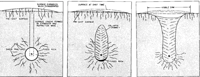
Fig. 1. Schematic illustration of underground testing phenomenology ..……….……….. 5
Fig. 2. Plot of cavity volume vs. crater volume ……….……… 7
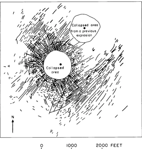
Fig. 3. Map illustrating surface cracks around a collapse crater at NTS .……….………… 10
Fig. 4. Photograph of surface crack through bedrock .……….……….. 11
Fig. 5. Cables typical of sophisticated diagnostic measurements .………..…..……….. 11
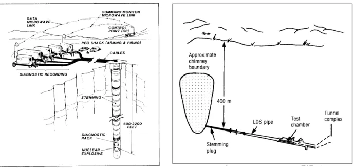
Fig. 6. Illustration of typical vertical and horizontal emplacements ………..………….……… 12
Fig. 7. Photograph of a field-portable GPS system ……… 19
Fig. 8. View of graded surface showing revegetated surface cracks ………. 26
Fig. 9. Crack in bedrock showing offset downward ………..……….……… 27
Fig. 10. Coaxial cables used for test diagnostics ………..……… 28
Fig. 11. Block spall along low cliff ………..……….. 29
Fig. 12. Newly opened crack in bedrock covered by a veneer of soil …..………..……….. 30
Fig. 13. Stemming material and perimeter fence post ………..……….……… 31
Fig. 14. Photograph of expensive fiber-optic cable ………..………..………. 31
Fig. 15. Reactivation of movement along an existing fault ……….……….………. 32
Fig. 16. Photograph of geologists recording field notes ……….……….……….. 33
Fig. 17. Carpetbag fault scarp ………. 33
LIST OF TABLES
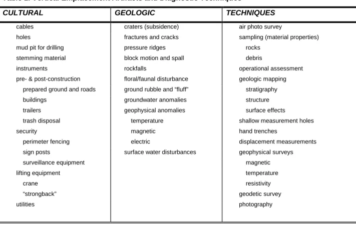
Table 1. Vertical Emplacement Artifacts and Diagnostic Techniques ………..………. 13Table 2. Horizontal Emplacement Artifacts and Diagnostic Techniques ...……… 14
Table 3. Equipment Required for Visual Inspection ………..……… 17
Table 4. Personnel Requirements ………..………. 18
VISUAL INSPECTION FOR CTBT VERIFICATION
by
Ward Hawkins and Ken Wohletz
ABSTRACT
On-site visual inspection will play an essential role in future Comprehensive Test Ban Treaty (CTBT) verification. Although seismic and remote sensing techniques are the best understood and most developed methods for detection of evasive testing of nuclear weapons, visual inspection can greatly augment the certainty and detail of understanding provided by these more traditional methods. Not only can visual inspection offer “ground truth” in cases of suspected nuclear testing, but it also can provide accurate source location and testing media properties necessary for detailed analysis of seismic records. For testing in violation of the CTBT, an offending party may attempt to conceal the test, which most likely will be achieved by underground burial. While such concealment may not prevent seismic detection, evidence of test deployment, location, and yield can be disguised. In this light, if a suspicious event is detected by seismic or other remote methods, visual inspection of the event area is necessary to document any evidence that might support a claim of nuclear testing and provide data needed to further interpret seismic records and guide further investigations. However, the methods for visual inspection are not widely known nor appreciated, and experience is presently limited. Visual inspection can be achieved by simple, non-intrusive means, primarily geological in nature, and it is the purpose of this report to describe the considerations, procedures, and equipment required to field such an inspection.
This report summarizes evidence supporting the validity of visual inspection as a worthwhile component of on-site inspection for CTBT verification. A well-based understanding of the visual features of underground testing is first required before inspection can be implemented for clandestine tests. In this light, further work on the field procedures and case histories, outlined in this report, are needed to develop a comprehensive operational manual for visual inspection. Specifically, field procedures need to be defined in more detail. This will require training, drills, and mock inspections. Case histories must be developed based upon a full literature search to compare and contrast successes/failures of visual inspection techniques.
I. INTRODUCTION
The draft Comprehensive Test Ban Treaty (CTBT) prepared by the Ad Hoc Committee on a Nuclear Test Ban (1996) stipulates on-site inspection (OSI) as a component of the treaty verification. The inspections will be carried out by designated personnel from members of the CTBT Organization. This aspect of the treaty results from conclusions drawn by experts at the 1994 Conference on Disarmament, who stated that OSI “should be an integral part of the overall CTBT verification regime and conducted with the view of obtaining scientific evidence which could be used to determine whether an ‘ambiguous’ event is a nuclear explosion carried out in violation of the Treaty’s provisions.”
Evasion ploys are a reality in potential treaty violations. Edward Teller testified before the Senate Disarmament Subcommittee in 1958 stating:
It would be a mistake to think underground tests are the only means of evasion. It is wrong to think that a net of seismic stations in the Soviet Union will make us safe. There are all kinds of other ways how a test moratorium could be circumvented. I would not like to go into this question because the subject is infinite. I should just like to assure you that the thinking along these lines has just started.
Numerous advances in seismic detection techniques since Teller’s pronouncement have addressed issues of testing in areas of natural or engineered (mining) seismic activity or by decoupling the explosion energy from the surrounding media by testing in a cavity (e.g., Bolt, 1976). One must acknowledge that any attempts at concealment require expensive and advanced engineering techniques, and that these techniques affect the testing environment. For example, Bolt (1976) shows that to optimally decouple a 50-kt explosion at a depth of 1.2 km would require a spherical cavity large enough to contain a thirty-five story building, and “concealment of such mining activity and dispersal of mined rock would be next to impossible.” While for tests of smaller yields or partial decoupling, the requirements for concealment are probably manageable, consider the experience gained from underground nuclear test containment at Nevada Test Site (NTS) where the ability to fully contain underground nuclear explosions required years of empirical and theoretical effort to achieve. One might conclude that concealment is not a trivial engineering feat, and it might dominate the test program if the program depended on it (see for example, “Caging the Dragon—The Containment of Underground Nuclear Explosions, ” Carothers et al., 1995).
Because experience with nuclear testing is dominated by underground deployment, we will limit this report to considerations of such tests. We assert the following statements in justification of our work described in this report.
1) Visual Inspection = Ground Truth: the most likely method for concealing a nuclear test on land is underground deployment
• Teleseismic interpretation is enhanced by detailed geologic knowledge of the source region.
• Testing will leave evidence of cultural activities.
• Visual inspection constrains or confirms possible source mechanisms (e.g., mining, tectonic, testing).
• Visual inspection documents the geology of the testing media (crystalline rock vs. alluvium) and for tamped shots the degree of likely seismic coupling.
• Visual inspection guides radionuclide and seismic aftershock detection by locating surface ground zero (SGZ) and identifying permeable pathways for gas escape.
2) Visual inspection of the “pink elephant” (no observable surface effects) is valid
• If on-site inspection is employed to investigate an area of suspected testing activity, remote (e.g., teleseimic, satellite) signals have prompted the investigation.
• Upon inspection, if no natural (geologic) or manmade (engineering) features explain the remote observations, a false negative is likely, and a major paradox must be explained.
3) Visual inspection can be achieved through simple means, primarily geological in nature
• Several key activities involve simple documentation of cultural, geological, and biological disturbances.
• Key activities have poor documentation and are not publicized, but they can be established by careful assessment of the nuclear testing experience base.
4) Visual inspection procedures must be defined for uniform CTBT implementation
• Presently there are no general procedures for visual inspection, no bounds on activities it encompasses, and no standardized approach.
• A document defining the process, the activities, the equipment, the personnel required, and applications of visual data can provide guidance for treaty negotiations.
Purpose of the work. Our ultimate objective is to produce a visual inspection manual that incorporates experience gained from underground nuclear testing programs in the U.S. and other countries. The manual is intended to define procedures, personnel requirements, and equipment, as well as serving as a reference guide for training designated personnel from the international organization (U.S. Department of Energy, 1994a). The manual will also address the issue of integration of visual inspection with other on-site inspection activities. We acknowledge that for such a manual to be effective for development of treaty protocol, it will require contributions and editing from other treaty countries and
approval through the treaty negotiations. While this report serves only as a primer, our goals for such a complete visual inspection manual include:
1) Describe visual inspection logistics, activities, personnel, and equipment.
2) Define diagnostic features and procedures for determining if an underground explosion has a nuclear source.
3) Suggest follow-on activities for data documentation and interpretation techniques. 4) Illustrate examples of visual inspection case studies.
II. FEATURES AND EFFECTS OF UNDERGROUND NUCLEAR TESTING
In this report we limit our realm of considerations to underground testing. While underground explosion phenomena can have both natural and manmade sources and many large manmade underground explosions are nonnuclear, our experience with nuclear testing has taught us that there are a number of surface/subsurface geologic, floral/faunal, and cultural effects that generally accompany underground nuclear testing. As described in the Threshold Test Ban Treaty (USACDA and USOSIA, 1990), there are two main underground testing designs: (1) vertical emplacement and (2) horizontal emplacement. While surface features can always be inspected, depending upon implementation of these testing geometries, subsurface features may or may not be accessible.
The phenomenology associated with underground nuclear testing (e.g., Houser, 1969; U.S. Congress, Office of Technology Assessment, 1989; Kunkle, 1994) includes these important aspects, illustrated in Figure 1. When an underground nuclear explosion occurs, the shock wave dynamically vaporizes and melts the rock in the immediate vicinity of the detonation point. The shock-induced outward motion and high internal cavity pressure cause the cavity to expand until the pressure has decreased to the point that the rock can no longer be deformed. The material then rebounds to form a large compressive stress field around the cavity. After cavity growth ceases and internal pressure drops below the amount necessary to support the overburden, the rock above the cavity falls into the void, forming a rubble chimney. Depending on the yield and overburden characteristics, collapse may extend to the surface forming a subsidence crater. As a result of cavity growth, rock fracturing may occur within several cavity radii of the detonation point. At the surface, reflection of the shock produces a rarefaction that propagates downward, causing spallation of surface materials. Surface cracks generally form within this zone of surface spallation and as a response to crater subsidence if it occurs. Geologic structure and pretest in situ stresses influence the nature and extent of fracturing in subsurface and surface materials. All of the above phenomena are strongly controlled by the depth of burst, rock lithology and structure, hydrogeology, and topography.
Adushkin and Spivak (1994) compiled one of the most comprehensive reviews of the geologic characterization of underground nuclear explosions. Their review covers experience gained from the underground testing of high-yield explosions for military use, peaceful use, the stimulation of energy and mass exchange in geologic media, and development of long-distance detection techniques. The geological regimes that form in test media after an underground explosion affect the media to ranges (r) scaled to the explosive yield in kilotons (kt). These regimes, though not always observed, include (1) the melt cavity where rock vaporization and motion have produced a void (r = 4 to 12 m/kt1/3); (2) the crushed zone where the medium has lost all of its prior integrity (r = 30 to 40 m/kt1/3); (3) the cracked zone characterized by radial and concentric fissures (r = 80 to 120 m/kt1/3); and (4) the zone of irreversible strain that causes local media deformation (r = 800 to 1100 m/kt1/3). While the scaled ranges of these regimes are highly dependent upon the test media structure and lithology (strength, compressibility, sound speed), rocks within these regimes experience irreversible explosion deformation resulting in changed porosity, permeability/filtration character, and material strength.
The following discussion covers surface and subsurface features and effects by describing their character. This discussion is not intended to be complete, but rather an outline of significant features [see also Hawkins (1983) and Allen et al. (1997) for a more detailed discussion]. Of surface features and effects, geological, cultural, and floral/faunal types can be observed, while subsurface effects are primarily geological in nature. While both surface and subsurface effects are strongly dependent upon the device yield and material properties of the test medium (geology), surface features develop as a function of depth of burial (DOB), scaled to device yield (W in kilotons), giving scaled depth of burst (SDOB): SDOB = DOB/W1/3. From Nevada Test Site experience, an SDOB of ~90 to 125 m/kt1/3 is sufficient to contain an underground test from releasing radioactivity to the atmosphere; this depth is approximately 9 to 10 times the cavity radius. However, surface collapse occurs in most (95%) contained underground tests in tuff with SDOB < 150 m, but only about half of the tests with SDOB < 180 m/kt1/3 cause surface collapse. It is apparent that with greater SDOB, the chance of producing surface effects decreases so that a clandestine test would be overburied with respect to that depth needed for containment. Considering the results provided by Adushkin and Spivak (1994), for which the zone of irreversible strain reaches up to 1100 m/kt1/3, concealment by overburial could be practically achieved for only small yields or decoupled configurations.
1. Surface Geological Effects from Underground Explosions
A) Craters. For underburied tests, surface materials may be accelerated to the point where they are launched as ejecta, leaving a surface crater with a surrounding apron of ejecta. Such craters are typically circular in plan view, conical in profile, and range in diameter and depth from a few tens of meters to several hundred meters, depending upon the yield and depth of burial (Nordyke, 1964; Glasstone and Dolan, 1977). The formation of a crater over an underground nuclear test would only happen in the event of inadequate clandestine test design.
B) Collapse Sinks. The cavity formed around the point of explosion generally collapses, producing a chimney of rubble that migrates upward within several minutes to hours after detonation. If the chimney reaches the surface, the rocks and soil sink, forming a crater that is generally bowl-shaped, ranging in size from a few tens of meters to nearly a kilometer in diameter and a few to several tens of meters deep. There are many notable variations of crater shape, including polygonal, irregular with reentrants, and steep to vertical walls. An important concept illustrated in Figure 2 shows that crater volume is logarithmically proportional to the size of the cavity needed to produce it. For situations of underground explosions, collapse craters of large size require cavity volumes in ranges produced only by nuclear detonations. We note that where testing is designed to avoid detection, surface collapse will be unlikely, but considering the NTS experience, scaled burial depth would have to be >110 m/kt1/3 in hard rock to 240 m/kt1/3 in soft rock in order to avoid surface collapse.
C) Depressions. Recognition of subsidence of broad areas over underground tests generally requires surveying techniques. Generally centered around SGZ and circular in shape, the amount of subsidence is generally greatest at SGZ, decreasing outward to several hundred meters away from SGZ (App, 1985; Houser, 1969, 1970). Where these structures interact with local geological structural features such as faults, the depressed area can take on an oblong shape.
Figure 2. Plot of cavity volume vs. crater volume (m3) for underground nuclear tests in alluvium. Note that the character of this plot should change for testing in different media and depth of burst (Kunkle, 1994).
D) Fractures. Fractures in rock and soil are caused by underground testing and are often referred to as “cracks”. Surface expression of these cracks are a manifestation of rock movement (due to propagation of stress waves and their reflection from the surface downward as a rarefaction) and subsidence of the chimney zone and crater. Cracks often follow zones of rock/soil weakness caused by tectonic faults and naturally occurring rock joints and have various dimensions. Explosion-produced cracks can be classified as radial, linear, and concentric (Figures 3 and 4). 1) Radial - Cracks that extend radially outward from a point at the surface directly above the
2) Concentric - Cracks that form roughly concentric to SGZ.
3) Linear - Cracks that have an orientation other than the radial and concentric cracks; they are indicative of preexisting geologic conditions and cultural features.
E) Other Features.
1) Pressure ridges - Linear zones of broken ground that are elevated from the surrounding surface.
2) Disturbed ground - Elongated zones of ground rubble that have the same elevation as the surrounding surface, or zones of inflated soil (“fluff”) caused by rapid accelerations.
3) Faults - Linear cracks with one side offset from the other (usually vertical).
4) Water table rise - Decrease in the depth to water in wells or new surface seepages. 5) Water impoundments - Evidence of water movement in ponds, tanks, etc.
6) Rock falls - On high angle slopes loose rocks may be displaced downhill. 7) Thermal anomalies - Present only where there has been cavity gas leakage.
8) Ground slump - Downslope movement of soil and rock along natural and manmade slopes.
2. Subsurface Geological Effects from Underground Explosions
A) Fractures. Cracks in the rock that are formed in a tunnel complex as a result of an explosion; they can be almost any orientation and dimension.
B) Bedding Plane Movement. Cracks and/or offsets that occur along contacts of different rock types are usually sub-horizontal.
C) Microfracturing. Zone near explosion that shows little distinguishable cracking but has been significantly weakened by the explosion.
D) Faults. Fractures that have offset (when radially oriented from the explosion point, the motion is always compressive).
E) Others.
1) Water seeps - Free water entering tunnel can be evidence of formation damage. 2) Tunnel deformation - Walls, floor, and ceiling may shift or collapse.
3) Thermal anomalies - Present in rock near the detonation point.
4) Rock hardness variations - Explosive-driven shock waves degrade rock hardness.
To conduct an underground nuclear test requires the utilization of facilities and equipment not normally associated with commercial operations. Additional security and safety issues must be addressed. Utility demands will be increased. Diagnostic instrumentation must be fielded to assess the performance of the explosive device.
A) Structures. Facilities required for the housing of sensitive equipment and special nuclear materials as well as scientific personnel (Boardman, 1970).
1) Roads - Roadways improved beyond what would be necessary for commercial operations. 2) Buildings - Secure and weatherproof facilities for technical activities associated with a test. 3) Surface preparation - Excessive surface excavation, treatment, and grading.
4) Wellheads and casing - Required for emplacement of explosive device (large diameter), subsurface instrumentation, and post-shot sampling tools.
B) Equipment. The execution of an underground nuclear test may require equipment not associated with regular operations and incorporates unusual levels of safety and precision.
1) Emplacement equipment - For a vertical emplacement, this would include lifting and backfilling equipment; for tunnel emplacement, loading and handling equipment not typical of commercial operations.
2) Instrumentation - Utilities (power, compressed air, ventilation, etc.) and sophisticated electronic equipment that are in excess of requirements for commercial activities. Cables which would be associated with data acquisition endeavors are typically expensive coaxial or fiber-optic types, only used for the highest quality data transmissions (Figure 5).
C) Other.
1) Containment features - Materials, equipment, and activities that would be necessary to contain radioactive gas and debris from escaping to the atmosphere (i.e., sealing of shaft/tunnel with low permeability - high strength materials, gas blocked cables)
2) Security precautions - Limited access areas with protective fencing and/or guards, and excessive surveillance equipment.
4. Floral/Faunal Features
Ground acceleration produced by underground nuclear tests can be sufficient to disrupt surface floral and faunal feature. Disruptions include felled trees, disturbed ground at base of trees, vegetation-filled lineations indicating previous cracking, disoriented/agitated wildlife, and renewed or destroyed animal burrows (Allred et al., 1965). These features are very sensitive to site environment.
Figure 3. Map illustrating surface cracks around a collapse crater at NTS. Note the radial, concentric, and linear cracks (Barosh, 1968).
Figure 4. Photograph of surface crack through bedrock.
Figure 5. Cables typical of sophisticated diagnostic measurements and a perimeter security fence post.
III. DIAGNOSTIC TECHNIQUES FOR VISUAL INSPECTION
As described above, underground nuclear testing is generally performed by one of two emplacement techniques: vertical or horizontal. Vertical emplacement requires drilling or mining a large-diameter shaft to the depth necessary to insure containment of explosive effects or conceal the test so that it can not be detected by obvious explosion-induced surface disturbances (Figure 6). On the other hand, horizontal emplacement is achieved by horizontally mining into a mountain or plateau or from a vertical shaft. In the horizontal case surface cultural features near SGZ will be minimal, but in both cases surface geological effects can be evident. Because of the difference in emplacement techniques, we expect that cultural and geological effects may differ and suggested detection techniques will similarly be somewhat different.
The following discussion of diagnostics and detection is based on a informal workshop held with LANL geologists and Bechtel Nevada scientists experienced with post-shot effects at the Nevada Test Site.
Figure 6. Illustration of typical vertical (left) and horizontal (right) emplacements of underground nuclear tests conducted at the Nevada Test Site (U.S. Congress, Office of Technology Assessment, 1989).
1. Vertical Emplacement
Table 1 lists expected cultural artifacts and geological/geophysical effects of underground nuclear testing by vertical emplacement. The table also shows characterization techniques used at the Nevada Test Site and expected to be useful in visual inspection activities.
Further work will expand this table to include site-specific considerations for other testing environments and further description of its contents.
Table 1. Vertical Emplacement Artifacts and Diagnostic Techniques
CULTURAL GEOLOGIC TECHNIQUES
cables craters (subsidence) air photo survey
holes fractures and cracks sampling (material properties)
mud pit for drilling pressure ridges rocks
stemming material block motion and spall debris
instruments rockfalls operational assessment
pre- & post-construction floral/faunal disturbance geologic mapping prepared ground and roads ground rubble and “fluff” stratigraphy
buildings groundwater anomalies structure
trailers geophysical anomalies surface effects
trash disposal temperature shallow measurement holes
security magnetic hand trenches
perimeter fencing electric displacement measurements
sign posts surface water disturbances geophysical surveys
surveillance equipment magnetic
lifting equipment temperature
crane resistivity
“strongback” geodetic survey
utilities photography
2. Horizontal Emplacement
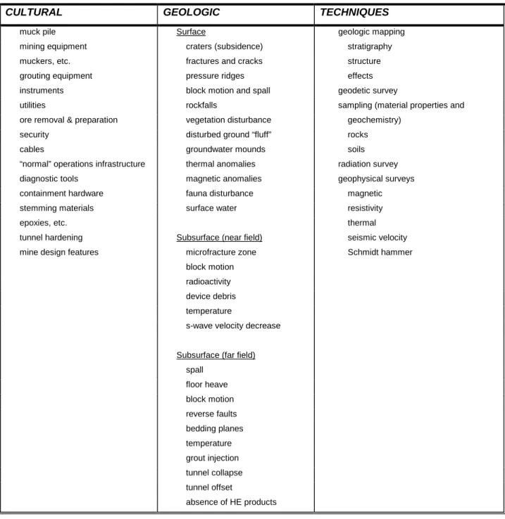
Table 2 lists expected cultural artifacts and geological effects of underground nuclear testing by horizontal emplacement. The table also shows characterization techniques used at the Nevada Test Site and expected to be useful for visual inspection activities.
Further research will expand this table to include site-specific considerations for other testing environments and further description of its contents.
Table 2. Horizontal Emplacement Artifacts and Diagnostic Techniques
CULTURAL GEOLOGIC TECHNIQUES
muck pile Surface geologic mapping
mining equipment craters (subsidence) stratigraphy
muckers, etc. fractures and cracks structure
grouting equipment pressure ridges effects
instruments block motion and spall geodetic survey
utilities rockfalls sampling (material properties and
ore removal & preparation vegetation disturbance geochemistry)
security disturbed ground “fluff” rocks
cables groundwater mounds soils
“normal” operations infrastructure thermal anomalies radiation survey
diagnostic tools magnetic anomalies geophysical surveys
containment hardware fauna disturbance magnetic
stemming materials surface water resistivity
epoxies, etc. thermal
tunnel hardening Subsurface (near field) seismic velocity
mine design features microfracture zone Schmidt hammer
block motion
radioactivity
device debris
temperature
s-wave velocity decrease
Subsurface (far field)
spall floor heave block motion reverse faults bedding planes temperature grout injection tunnel collapse tunnel offset absence of HE products
IV. PROCEDURES
The experts of the 1994 Conference on Disarmament concluded that “OSI should be conducted in the least intrusive, most cost-effective and timely manner, consistent with the effective achievement of its objectives.” Although the study of surface effects of underground testing at the NTS has a long history, documented in numerous reports and memoranda, that effort has been directed at planning and siting of tests (e.g., Howard, 1983), the understanding of geologic phenomena, and identification of features that
might adversely affect containment. For this reason, no standard procedures exist for visual inspection. Garcia et al. (1989) began an effort to standardize and document the procedures used in mapping surface effects at the NTS, but their effort remains unfinished and unpublished. To begin a remedy for this lack of visual inspection procedures, we offer the following section as an outline of the activities, logistics, and personnel we envision as necessary procedural components of a visual inspection.
1. Activities
The basic approach to visual inspection activities involves a remote-to-target strategy. This approach follows these steps: (1) initial efforts will compile as much geological and cultural information around the target site as possible by literature searches, remote sensing techniques, aerial photography, and seismic records; (2) with data from step 1, a rough reconnaissance map will be compiled, showing access routes, target objects such as geologic contacts and structural features, and evidences of human activities; and (3) on-site documentation of features on the reconnaissance map with addition of new features and supporting data. This last step will consist of four components as described below. Each component will add to the observational data base and allow the design of diagnostic geological, geophysical, and sampling tests to be performed. The summarized procedures described below are further discussed by Allen et al. (1997).
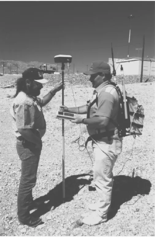
A. Reconnaissance and Initial Visual Survey. After obtaining access to the target area and setup of necessary support facilities (e.g., housing, communications), the rough reconnaissance map will be checked. The area encompassed by this map is expected to range from a few square kilometers to as large as 100 km2 (not to exceed 1000 km2), based upon the scaling relationships for irreversible strain given above where the effects of a large (1 Mt) test might extend 10 km from the explosion point. This range should allow observation of the natural (undisturbed) environment for a comparison basis and to establish “background” conditions. The initial visual survey may require special transport vehicles (e.g., ATVs—all-terrain vehicles) in order for designated personnel to completely cover the area to verify objects found by remote techniques and to add new features. Location of all features will be accomplished through use of a Global Positioning Satellite (GPS) system. For example, Figure 7 shows use of GPS that allows rapid and accurate geodetic measurements for mapping features in a test area. The results of this reconnaissance and initial visual survey will provide a working map serving as a reference for ensuing activities. Sites for geological sampling, geodetic surveys, or detailed geophysical measurements will be designated at this point.
B. Photo Documentation: Aerial, Surface, and/or Subsurface. On-site photography will document all features identified on the working map by location and type (geological, cultural, biological). If the site includes mine shafts and boreholes, subsurface photographs will be made where possible. If permitted, aerial photography by low-altitude (up to 1500 meters above the surface) overflights will provide a photographic basis for the working map and augmentation of previously obtained aerial photos or remote
images. Photogrammetric mapping techniques developed by Van de Werken (1983) and Garcia (1987, 1989) were developed specifically for documentation of surface effects.
C. Geological, Topographic, Cultural Feature Mapping. Detailed mapping activities will focus on the acquisition of as much information as possible on the location of different geological media, their contacts and structure. Detailed mapping will also involve description of topographic/geomorphologic elements, some of which will require precise geodetic surveys. Drellack (1988, 1989) and Baldwin and Townsend (1995) provide a framework upon which mapping procedures can be based. In addition, cultural features, such as roads, buildings, and debris from human activities, will be mapped and described in detail.
D. Sampling, Geological and Geophysical Measurements, and Geodetic Survey. With compilation of
a detailed site map, specific areas will be designated for sampling, geological/geophysical, and geodetic survey activities. The purpose of these activities will be to test hypotheses that nuclear testing has occurred within or under the map area. A complete set of detailed procedures has yet to be defined, but the implementation of those procedures at a given site will be based on the unique characteristics of the site and its studied objects. Apart from radiological/chemical sampling, which is a separate activity, visual inspection sampling is important for activities that will determine any media damage by explosive shock, rock properties important for understanding seismic wave propagation, and relative age of site alterations by human activities. Geological/geophysical measurements (see Tables 1 and 2) will document the existence and location of the possible geological artifacts of nuclear testing. These exercises will require geodetic information from designated surveys.
At the time of writing this report, no standard methodology exists for these general activities, using techniques described in the Tables 1 and 2. However, a document of methods, prepared by Allen et al. (1997), is being drafted, based on their experience with post-shot investigations at the Nevada Test Site (e.g., Drellack, 1988).
2. Logistics and Equipment
Logistics includes the overall infrastructure of the visual inspection team, how the team is deployed, chain of authority, how information is exchanged, communication, reporting, and documentation requirements, on-site support, and negotiations with the testing party. Equipment needs are also part of the overall logistics because such equipment will have to be transported within the host country, certified and regulated by treaty protocol, and strictly maintained for operations and accountability.
Table 3 shows a list of equipment desired for visual inspection by activity type. This equipment represents what is typically applied to geological investigations, and it has proven to be useful for characterization and documentation of nuclear test effects and artifacts. In Section VI of this report we
describe example activities that incorporate some of the equipment listed below. Operational equipment includes notable logistical support (transportation, lodging, interpreters, etc.), materials and supplies for general on-site operations, and provisions for safety and industrial hygiene. Visual and surveying equipment is necessary for effective mapping (location) and documentation. Geological equipment is required to make direct measurements and characterize visually apparent surface and underground features and effects. In contrast, geophysical equipment is useful for non-intrusive measurement of features and effects that are not usually visible but nonetheless important for a complete characterization, especially where observable features have been purposely concealed. For example, radiation detectors used for rock property characterization can make positive detection of underground testing even in areas where there are no visual clues.
Visual inspection logistics for designated personnel, on-site operations, and equipment specifications, costs, training procedures, and transportation alternatives have not been developed for the CTBT, but we suggest the TTBT protocol as a model.
Table 3. Equipment Required for Visual Inspection
OPERATIONAL VISUAL/SURVEYING GEOLOGICAL GEOPHYSICAL
personal computer binoculars Brunton compass Schmidt hammer
drafting and office supplies GPS transit seismometer and geophones
all-terrain vehicle 35 mm cameras thin section machine material properties kit
communications Polaroid cameras petrographic microscope bulk density
industrial hygiene video cameras geologist hammer psychometer
Drager tubes tape measure shovel and pick gas analysis
PPE altimeter Jacob’s staff radiation monitors
combustible gas indicator stereoscope geological maps KUT, beta, gamma, alpha
flame ionization detector aerial photos sample containers magnetometer photoionization detector topographic maps air samplers thermal detector
oxygen meter transit 6’ soil auger shallow borehole logging sondes
decontamination setup bulk density meter
radiation safety neutron logger
3. Personnel
A key component to an OSI will be the personnel involved with visual examination of the site and their systematic recording of their observations. In addition to expertise in specific aspects of visual inspection, the OSI team should include personnel familiar with equipment used in testing and diagnostic evaluation of nuclear explosions as well as normal commercial operations.
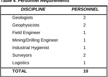
Table 4 lists personnel by discipline and minimum number to complete activities within a reasonable time frame. At the time of writing this report, there is not enough information available to address considerations of actual time needed for operations allowed for visual inspection; however, there is a 60-day limit, which can be extended an additional 70 days. From experience at the Nevada Test Site, 2 geologists can complete field geologic mapping of the effects of a low-yield event in several days, while for larger events in rugged terrain, 4 geologists might require several weeks. Training will play a major role in selection of team members (e.g., the team might benefit from a geologist familiar with the geologic setting of a particular test area).
Safety is a major component of all personnel activities. Work in the vicinity of SGZ might present specific hazards, but weather and natural hazards are always a factor. Considerations of heat and cold, dehydration, indigenous wildlife, topography, and disorientation must be addressed when sending a field team out. Hazards for radiological and chemical exposure are expected in test areas, as are those of operations of vehicles, drilling/construction equipment, and postshot surface collapse, block fall, and gas release.
Table 4. Personnel Requirements
DISCIPLINE PERSONNEL Geologists 2 Geophysicists 2 Field Engineer 1 Mining/Drilling Engineer 1 Industrial Hygienist 1 Surveyors 2 Logistics 1 TOTAL 10
Figure 7. Photograph of a field-portable GPS system using a base station system for precise location.
V. CASE STUDIES
The following summary covers a short-list of underground tests to illustrate some of the environments where test experience is documented and locations where follow-up studies have highlighted visual effects. While information on U.S. tests is emphasized in this present report and that done by Bechtel Nevada staff (Allen et al., 1997), an extensive literature research will be required to uncover experience at foreign localities. Future work should include a comprehensive review of testing experience with respect to geological, cultural, and floral/faunal effects, including characterization techniques.
1. Nevada Test Site
Underground testing at the NTS (U.S. Department of Energy, 1994b) has involved 828 nuclear explosions, dating from 1951, in 3 major areas: (1) Yucca Flat, (2) Pahute Mesa, and (3) Rainier Mesa. From the late 1950s until 1977, the U.S. Geological Survey documented surface effects of many underground tests, compiling composite surface effects maps for these different NTS areas. In addition to efforts by the U.S. Geological Survey, since 1977 responsibility for surface effects mapping has included the individual testing organizations.
A. Yucca Flat. Yucca Flat has been a principal site for underground nuclear tests. An intermontane basin and piedmont area, this area is underlain by alluvium reaching a thickness in excess of 600 m in the south-central part of the basin. Below the alluvium are Tertiary tuffs (~600 m thick), which rest on basement rock of Devonian to Cambrian carbonate rocks containing aquifers.
The surface of Yucca Flat is pockmarked by numerous collapse sinks ranging from 3 to 244 m in radius and 0.6 to 61 m in depth (Houser, 1970). Not all of the sinks are centered at SGZ, but most are well defined with a circular to elliptical shape, and for those tests conducted in the volcanic bedrock, sinks may be elongated.
Underground nuclear tests produce notable fractures in the overlying alluvium in radial and concentric patterns around test SGZ (Figure 3), but many of these fractures rarely extend to a depth beyond 30 m; most are usually widest at the surface and narrow with depth (Carr, 1965). Other fractures commonly align along preferential trends spatially related to the Yucca fault system or parallel bedrock joint patterns in bedrock adjacent to the valley, especially if the tests have been conducted in the bedrock below the alluvium (Barosh, 1968). These fractures in the soft Yucca Flat alluvium tend to fill with sediment relatively quickly. Where faults occur in Yucca Flat, they are subject to displacements up to 0.5 m by nearby underground tests within scaled distances of 150 to 300 m/kt1/3 (Dickey, 1968). In these areas, fractures generally parallel the fault.
B. Pahute Mesa. Events in Pahute Mesa show surface effects generally including movement and extensions along previously known faults, movement on previously unknown faults, often ill-defined, generally asymmetric (with respect to SGZ) sinks, noticeably present radial and concentric fracture patterns, generally widespread cliff spall, and numerous and lengthy pressure ridges (Snyder, 1971; Maldonado, 1977). The high-yield (1.3 Mt) Boxcar event induced 1 m of horizontal and 0.1 m of vertical movement on a fault along which fractures were mapped for more than 6000 m from SGZ.
C. Rainier Mesa. Diamond Sculls was a low-yield (<20 kt) event detonated 424 m under Rainier Mesa in tunnel U-12t.02 in 1972. Surface effects mapping on aerial photographs at a scale of 1:4800 showed bedrock fracturing in areas where previous faults had been mapped (Snyder, 1972). Although no definite sink was apparent, fracture patterns north of SGZ might have indicated an incipient collapse structure. The event caused development of five major sets of fractures extending up to several hundred meters long with displacements of up to 0.3 m. Most of these fractures occurred within 500 m of SGZ.
D. Others. Other localities at the NTS that require more study with regards to surface effects are (1) Frenchman Flat, (2) Mine Mountain, (3) Buckboard Mesa, and (4) Climax mine.
2. Off-Site
A. Alaska (Amchitka Island). Long Shot, an 80-kt nuclear test detonated in October 1965 at a depth of 700 m on Amchitka Island, provided an experiment to record seismic wave arrivals and document the surface geologic, hydrologic, and tectonic (structural) effects of the explosion (McKeown et al.,1967). Extensive pre-shot documentation of existing geologic and hydrologic conditions characterized the site as a mildly undulating, swampy tableland, underlain to a depth of about 6 m by peat and to about 1200 m by the Banjo Point Formation of volcanic breccias and sediments. The site is bounded to the northwest and southeast by two major parallel normal faults, striking northeast and part of a larger tectonic framework of northeast-striking faults. The bedrock is saturated, and surface streams connect numerous small ponds and lakes.
The shot produced many surface effects, including ground cracks, movement of loose manmade/natural objects, rockfalls, slumping, building damage, and hydrologic effects, including mud geysers and tilting of ponds. Road cracks and movement of various materials extended to 2300 m south and 1130 m north of SGZ. The surface effects were sporadically distributed, and the most common ones were ground cracks, ranging from hairline to a few centimeters in width and a few centimeters to over 100 m in length up to 4000 m from SGZ, as discovered by the on-site inspection team. Occurring in relatively loose, unconsolidated ground, cracks generally formed a bread-crust-like pattern, but surface turf and peat concealed more than 90% of the ground within the fractured zone. Major ground cracks were parallel
with the tectonic fabric, striking northeast, and showed as much as 15 cm of vertical displacement. Associated with these major ground cracks were pressure ridges, thought to have been produced by explosion-induced movement along the fault to the north of SGZ. Ground compaction and mud cracking was fairly conspicuous and produced up to 15 cm of settling around manmade structures. Rockfalls occurred within 1700 m of SGZ along the sea cliffs. Minor surface effects included slumping of the sides of trenches and banks of ponds as well as the movement of boulders and other objects for a distance of up to 30 cm over the turf in a direction generally away from SGZ. Hydrologic effects were also visible and included mud geysers, which coated grasses with mud near small bodies of surface water, and changes of pond and lake water levels.
Milrow (1 Mt), conducted on Amchitka in October 1969, was a much larger underground nuclear test than Long Shot. Detonated in lavas and breccias at a depth of 1218 m about 3 km south of Long Shot, visible geologic effects were few and of limited extent (U.S. Geological Survey, 1970). The visible effects were similar to those of Long Shot and included rockfalls, turf falls, slumping, cracking, and soil disturbances. The surface displacements were few and small (compared to those documented at the NTS), which is thought to be a result of the underlying peat formation, which flexed rather than broke in response to the explosion. Although several known faults existed near SGZ, there was no surface indication of induced cracking or displacement along them. The most obvious surface effects of Milrow were numerous rockfalls along the sea coast, several kilometers away from SGZ. Slumps, formed in areas of unconsolidated sand and gravel, especially on steep slopes near borrow pits, road beds, a runway (7 km from SGZ), and a lake, produced large, open, arcuate cracks up to 1.5 m deep. Soil disturbance included displacement of rocks within 2.5 km of SGZ and turf disruption, noted by randomly oriented cracks as much as 15 cm wide and 60 m long within 700 m of SGZ. About 36 hours after the test, chimney collapse formed a depression over SGZ 540 m wide and up to 6 m deep.
Cannikin event (< 5 Mt) surface effects have also been investigated (U.S. Geological Survey, 1972, 1974).
B. Colorado. Rulison was tested 70 km north of Grand Junction in 1969 at a depth of 2570 m in
sandstone and shale. Designed to stimulate natural gas production, this 40-kt explosion increased the wellhead pressure by a factor of six for several months. A similar gas stimulation test (Rio Blanco) was conducted in 1973 at Rifle, Colorado, involving simultaneous firing of three 33-kt devices in a shaft.
C. New Mexico. Gasbuggy was conducted near Farmington, New Mexico, in 1967 to test the
effectiveness of nuclear explosion for large-scale natural gas stimulation. Fired at a depth of 1300 m below the surface in sandstone, this 29-kt explosion produced no documented seismic damage. Gnome (3 kt) was fired in salt near Carlsbad, New Mexico, in 1961. It formed a cavity ~50 m in diameter and ~21 m high.
D. Mississippi. Salmon (5.3 kt) and Sterling (0.38 kt) were conducted near Hattiesburg, Mississippi, in 1966. Emplaced in a salt dome, Salmon was fired to make a cavity to test Sterling.
3. Foreign Test Sites
A. Russia. Reviewed by Adushkin and Spivak (1994), Russian nuclear tests have been conducted in two major areas. The Semipalatinsk Test Site was founded in 1948 with the first nuclear explosion tested in 1949 and the last in 1989. Of the 467 nuclear tests performed there, 345 were underground, the first of these underground experiments conducted in 1961. In the central hummocky, low-mountain topography of Central Kazakhstan, Semipalatinsk geology is dominated by its block structure and a wide range of crustal rock types: the Balapan area is underlain by a hard-rock basement of Paleozoic and Mesozoic age covered by a variable thickness up to 100 m of soft sediments, and the Degelen area is located in a granitic intrusive massif.
Novaya Zemlya, founded in 1954, is the site of 132 nuclear tests (until 1990) of which 45 were underground. The geology of the site is characterized by low epiplatform mountains developed in Upper Cambrian and Silurian sandstones, quartzites, shales, and limestones. Permafrost extends downward from the surface to an average depth of 480 m. Adushkin and Spivak emphasize that the effects of underground nuclear tests are dominated by the preexisting geologic structure, which for these Russian test sites is characterized as “block structure”, individual pieces of the earth’s crust bounded by tectonic faults and fractures. The spacing and orientation of faults and fractures dictate the size of the blocks. While much of the geologic deformation is transferred along these faults and structures, individual blocks can respond to an explosion in different ways depending on how they “filter” the signal produced by the explosion. As mentioned earlier in this report, the results of surface effects studies of Russian tests have been directed toward predictive capabilities in order to determine the types and degrees of rock damage with distance from the explosion as a function of yield.
B. France. France has tested buried nuclear explosions in granite rock in Algeria and in basalt below a coral reef in the Pacific ocean.
C. China. China’s early nuclear tests were atmospheric, but information on any underground testing is not readily available.
VI. NTS VISUAL INSPECTION EXERCISE
In order to evaluate the visual inspection methods that we have outlined in this report, we designed an exercise at the Nevada Test Site. Several historic underground nuclear test locations were visited to conduct the reconnaissance with an initial visual survey, using preliminary photo documentation. The objectives were to (1) use aerial photos and topographic maps to find the likely area where testing occurred; (2) document surface features (cultural, operational artifacts, geologic disturbances, etc.); and (3) analyze the visual data to assess whether enough clues remained to suggest that underground nuclear testing had been conducted and if so, where SGZ was located. We note that this exercise does not include situations where there has been the attempt at concealment by overburial, low yield, decoupling, and/or surface restoration after the test. By establishing a reference basis for obvious surface effects of underground nuclear tests, we will have a foundation upon which to build future methods to address concealed tests. However, for this report, we note that most of the test areas inspected are sufficiently old that natural revegetation and surface modifications have obscured evidence of testing activities to the point where they are not easily distinguished with aerial photos. Eleven candidate underground tests were selected by a third party to represent sites where surface visual features are evident. We chose five sites (Table 5) for the inspection exercise. Only approximate locations were given and our task was first to identify these approximate locations on topographic maps and aerial photos and then plan methods of access by roads or trails. Once in the general area where we suspected the test, we surveyed the area for visual clues of past activities. These clues included ground and vegetation disturbances, operational artifacts, and geologic disturbances.
The following summaries briefly highlight our findings and interpretations, from which we conclude that careful visual inspection can reveal a number of evidence types that indicate the nature of past underground testing activities.
Table 5. Candidate Sites for Visual Inspection Exercise Hole
Name
Event Name Date of
Test DOB (m) Announced Yield (kt) Geologic Setting
U-19az Houston 11/90 594 20 - 150 Tested in hard rock with little soil cover near mesa edge
U-19ab Towanda 5/85 661 20 - 150 Tested in welded tuff below a narrow valley
U-3lt Minero 12/84 244 <20 Center of cluster of tests below sandy alluvium
U-3me Kinibito 12/85 579 20 - 150 Near major fault
U-2dg Carpetbag 12/70 662 220 Along major fault in alluvium-filled valley underlain by tuff
1. Houston (U-19az)
The location of this test area was complicated by the fact that it was in an area of previous cultural activity over 1 to 2 km2, consisting of prepared surfaces and roadways. Inspection of the area quickly showed that a group of security perimeter fences still circled areas of past activities. From aerial photograph inspection, it was determined that Houston was the southernmost fenced area of the group, but accessibility by auto had to be assessed to find a safe means of approach over soft ground. The perimeter fence was still standing and an obvious “strongback” (a steel structure anchored in concrete for supporting heavy downhole weights) indicated the suspension of a large mass. Although no subsidence crater was evident, ground cracking was clearly apparent on the smooth prepared surfaces, which conspicuously lacked the normal vegetation for this area. The cracks were revealed by vegetation (Figure 8), such that linear traces of grass about 15 cm wide formed a crisscross pattern on the surface. This pattern defined traces extending radially away from the perimeter fence as well as concentric about the fence. Upon further inspection, the grass traces formed in linear depressions only a few centimeters wide that had collected enough rainfall to support new vegetation. This crack pattern extended over a roughly circular area more than 200 m wide centered about the strongback. Cracks were also present in the welded tuff bedrock surrounding the prepared surfaces, and these showed evidence of having been formed recently since they were not filled with detritus as one would expect on geologically formed surfaces. Also, some of these cracks in the bedrock showed offset downward towards the strongback (Figure 9). The surface within the perimeter fence was strewn with dozens of coaxial cables (Figure 10)
that extended from the strongback out to the perimeter fence, and a mound of pea gravel typical of stemming material was observed within the fenced area.
The combination of extensively prepared ground, stemming material, surface cracks suggestive of underground subsidence, coaxial cables used for sophisticated monitoring devices, and a strongback typically used to suspend a heavy object are strong indications of an underground explosion. There is no evidence of economic mining in the area, nor did geologic exposures present evidence of minerals. It remains unclear as to whether or not the explosion was nuclear, but it is hard to justify the existence of the numerous cables for anything but a sophisticated test. Follow-up work could use mapped surface features to delineate areas for radionuclide and aftershock monitoring.
Figure 8. U-19az (Houston). View of graded surface showing revegetated surface cracks defining concentric and radial patterns that indicate a central point likely to be SGZ.
Figure 9. Crack in bedrock showing offset downward toward the area of prepared ground and presumably SGZ. Note the 10-cm ruler for scale.
Figure 10. U-19az (Houston). Coaxial cables used for test diagnostics are usual features of nuclear testing.
2. Towanda (U-19ab)
Careful use of topographic maps and aerial photos guided our search up a small valley that showed no signs of any operations other than a poorly defined track. On approach to the test area, our first clue was a graded area in the valley along one side of the track that was unvegetated. Aerial photos showed this area to be of a size necessary for a staging platform. Within several hundred meters of this area, amidst bushes over a meter high, we found a perimeter fence extending across the valley over an area about 200 m wide, and a steel well casing protruding from the ground. Further inspection revealed numerous coaxial cables strewn across the ground and generally leading to a central location within the fenced area. The fenced area was bounded on one side of the valley by low cliffs of bedrock that showed numerous blocks spalled from their face, the blocks showing light-colored unweathered faces in stark contrast to the desert varnish on most bedrock surfaces (Figure 11). Closer inspection of the low cliffs showed open cracks in the bedrock extending radially away from the center of the fenced area (Figure 12). The cracks ranged in width from 4 to 15 cm with exposed lengths of over 10 m. Although much of the bedrock was covered by soil ~0.5 m thick, the cracks were unfilled, empty to a depth approaching 2 m.
The existence of a graded area, a perimeter fence, coaxial cables, and protruding well casing suggests underground operations. But the conspicuous block spall and large rock cracks strongly indicate that large-scale rock movement occurred in this area, rock movement that could only be explained by a recent earthquake or detonation of a very large underground explosion. Because of the proximity to an area showing cultural artifacts not typical of a mining operation, the surface cracking and block spall suggest underground testing of a nuclear device.
Figure 11. Block spall along low cliff near perimeter fence of Towanda. Note the light-colored fracture surfaces (fresh) in contrast to the darker (old) surfaces.
Figure 12. U-19ab (Towanda). Newly opened crack in bedrock covered by a veneer of soil. Such cracks may follow preexisting joint patterns in the bedrock, but to show this much fresh opening, require recent ground motion of large amplitude.
3. Minero (U-3lt)
Located in a wide desert valley, this site was among several possible test locations easily distinguishable on aerial photos. Topographic maps showed numerous access roads crossing the area. The site was marked by a conspicuous subsidence crater ~100 m wide and ~10 m deep (Figure 13). The crater was bounded by a perimeter fence, and numerous cables lay strewn across the area. Many of the cables were of the fiber-optic type (Figure 14). Primarily radial surface cracks were delineated by vegetation along which compass bearings were measured and plotted to pinpoint SGZ.
The large subsidence crater, fiber-optic cables, radial cracking, and stemming material are all typical sorts of geological and cultural effects of nuclear underground testing. For this geologic situation in a desert alluvium-filled valley, where mining activities, maar volcanism, or other crater-forming processes are absent, such a large crater and related cultural features are strongly indicative of nuclear testing.
Figure 13. Minero collapse sink showing stemming material and perimeter fence post in foreground. Geologist is using a radio to communicate with teammate at the other side of the sink (arrow).
Figure 14. Photograph of expensive fiber optic-cable found at Minero. Such cable is used only for high-quality data transmission suggesting a sophisticated application.
4. Kinibito (U-3me)
This test area is located along a desert basin fault, and the area was well marked by an extensive area of prepared ground stretching nearly 0.5 km from a fenced area of prepared ground. Tangential to the fenced area on the flat valley floor was a recent fault scarp that showed up to 0.5 m of vertical offset where it was within ~1 km of the fenced area (Figure 15). The scarp cut a desert pavement and produced disturbed ground (fluff). During our investigations, use of a portable computer saved time in compiling observations and measurements, while allowing rapid access to reference materials (Figure 16).
If underground testing has occurred in a geologic environment characterized by through-going tectonic faults, detonation of nuclear devices will likely produce new movement on those faults, which can be readily observed (Dickey, 1968; Hawkins, 1983). This observation is particularly important for interpretation of teleseismic and aftershock signals because they will be influenced by both the explosive source and renewed fault activity.
Figure 15. Reactivation of movement along an existing fault near the test area (Kinibito), showing offset of desert pavement (just to the top left of the field notebook shown for scale). Along this fault, which was only prominent near the test area, the soil was disturbed, being inflated or “fluffed” as a result of rapid vertical acceleration and slap-down not characteristic of natural tectonic movement.
Figure 16. Photograph of geologists recording field notes and map information on a portable computer during field operations at an inspection site.
5. Carpetbag Area (U-2dg)
The Carpetbag fault was unknown prior to the event of the same name. We offer this example to show how dramatic reactivation of a major fault can be when triggered by a large underground nuclear test. Figure 17 shows the main scarp of the Carpetbag fault.
Figure 17. Carpetbag fault scarp showing ~3 m of vertical offset. The lower 2 m of vertical scarp defines offset produced by the Carpetbag event while the upper 1 m is sloped as a results of erosion on an earlier natural fault movement. The area to the right of this fault is a graben structure ~0.5 km wide and ~2 m deep that was formed during the nuclear test. Such large-scale fault reactivation is unknown by any other human activity other than nuclear testing.
VII. CONCLUSIONS
In this report we have summarized our investigation of visual inspection as an integral component of on-site inspection for CTBT verification. Our approach included literature reviews, an informal workshop and interviews with personnel experienced with post-shot effects, features, and operations of underground nuclear testing, and field exercises to evaluate the effectiveness of visual inspection techniques. In giving a brief overview of underground nuclear test phenomena and their effects on cultural, geological, and floral/faunal features, we have illustrated the basic components of visual inspection. Important considerations include knowledge of the geological setting and test emplacement configuration. Although horizontal and vertical emplacement techniques will produce similar cultural and geological effects, there may be significant differences in inspection techniques required for each. In this report, we have only outlined general procedures, logistics, equipment, and personnel expertise required for visual inspection. Although case histories have been mentioned briefly in this report, we strongly feel that they should be expanded to fully cover available literature with special attention to include foreign test sites. The visual inspection exercise described in this report serves to illustrate the type of work that needs to be done at other test sites in order to more fully develop the procedures. Field studies at foreign sites might afford valuable experience for inspection in territories where less is known about nuclear testing features. In conclusion, with this discussion of visual features and documentation techniques and the brief illustrations of our field exercises, we have shown how visual inspection is accomplished and why it is an essential component of an on-site inspection.
REFERENCES
Ad Hoc Committee on a Nuclear Test Ban, 1996, Draft comprehensive test ban treaty: Conference on Disarmament CD/NT/WP.330/Rev.1, Geneva.
Adushkin, V. V., and Spivak, A. A., 1994, Geologic characterization and mechanics of underground nuclear explosions: Defense Nuclear Agency Tech. Rep. (Contract No. DNA 001-93-C-0026), Alexandria, VA.
Allen, B. M., Drellack, S. L., and Townsend, M. J., 1997, Surface effects of underground nuclear tests: Geology/Hydrology Group report, Bechtel Nevada.
Allred, D. M., Beck, D. E., and Jorgensen, C. D., 1965, A summary of the ecological effects of nuclear testing on native animals at the Nevada Test Site, in Proceedings of the Utah Academy of Sciences, Arts, and Letters, vol. 42, Part 2, pp. 252-260.
App, F. N., 1985, Permanent displacement of the ground surface resulting from underground-nuclear-test-induced ground shock, in Olsen, C. W., and Donohue, M. L., eds., Proceedings of the Third Symposium on Containment of Underground Nuclear Explosions: Lawrence Livermore National Laboratory Proceedings, CONF-850953, v. 2, pp. 409-424.
Baldwin, M. J., and Townsend, D. R., 1995, Geotechnical source book for DNA underground weapons effects tests: Raytheon Services Nevada Report TSP:DGP:071:95.
Barosh, P. J., 1968, Relationship of explosion-produced fracture patterns to geologic structure in Yucca Flat, Nevada Test Site, in Eckel, E. B., ed., Nevada Test Site: Geological Society of America Memoir 110, pp. 199-217.
Boardman, C. R., 1970, Engineering effects of underground nuclear explosions, in Proceedings -Symposium on Engineering with Nuclear Explosives: American Nuclear Society and U.S. Atomic Energy Commission Report CONF-700101, vol. 1, pp. 43-67.
Bolt, B. A., 1976, Nuclear explosions and earthquakes, the parted veil, W. H. Freeman and Company, San Francisco, 309 pp.
Carothers, J. E., et al., 1995, Caging the dragon—The containment of underground nuclear explosions: U.S. Department of Energy Report DOE/NV-388, Defense Nuclear Agency Report DNA-TR-95-74, 726 pp.
Carr, W. J., 1965, Preliminary results of subsurface investigation of fractures in Yucca Flat, Nevada Test Site: U.S. Geological Survey Technical Letter Yucca-57, 15 pp.
Dickey, D. D., 1968, Fault displacement as a result of underground nuclear explosions, in Eckel, E. B., ed., Nevada Test Site: Geological Society of America Memoir 110, pp. 219-232.
Drellack, S. L., 1988, Crack mapping procedures: Informal Memo Geo-0451, Fenix & Scisson, Inc., 6 pp. Drellack, S. L., Jr., 1989, Fenix & Scisson post-shot surface effects mapping procedures: Fenix & Scisson
training procedure GP-001, 8 pp.
Garcia, M. N., 1987, Photogrammetric method for determining sink volumes at the Nevada Test Site, in Olsen, C. W., Donohue, M. L., and Wander, S., eds., Proceedings of the Fourth Symposium on Containment of Underground Nuclear Explosions: Lawrence Livermore National Laboratory Proceedings, CONF-870961, v. 2, pp. 446-455.
Garcia, M. N., 1989, Photogrammetric methods applied to surface mapping and volumetric studies at the Nevada Test Site, Nevada: Photogrammetric Engineering and Remote Sensing, v. 55, no. 8, pp. 1197-1201.
Garcia, M. N., Drellack, S. L., Jr., and McKinnis, W. B., 1989, Field and photogrammetric procedures for mapping surface effects produced by subsurface nuclear testing at the Nevada Test Site, Nye County, Nevada: U.S. Geological Survey unpublished Open-File Report (draft).
Glasstone, S., and Dolan, P. J., 1977, The Effects of Nuclear Weapons (third edition): U.S. Department of Defense and the Energy Research and Development Administration, U.S. Government Printing Office, Washington, D.C., 653 pp.
Hawkins, W., 1983, Review of surface effects from underground nuclear explosions near the Yucca Fault, Nevada Test Site, in Olsen, C. W., compiler, Proceedings of the Second Symposium on the Containment of Underground Nuclear Explosions: Lawrence Livermore National Laboratory Proceedings, CONF-830882, v. 3, pp. 115-137.
Houser, F. N., 1969, Subsidence related to underground nuclear explosions, Nevada Test Site: Seismological Society of America Bulletin, vol. 59, no. 6, pp. 2231-2251.
Houser, F. N., 1970, A summary of information and ideas regarding sinks and collapse, Nevada Test Site: U.S. Geological Survey report USGS-474-41, 129 pp.
Howard, N. W., 1983, LLNL site characterization for containment of nuclear tests: Lawrence Livermore National Laboratory Report UCRL-53446, 33 pp.
Kunkle, T. D., 1994, An Introduction to Underground Nuclear Phenomenology or What Happens When the Bomb Goes Off: Los Alamos National Laboratory Personal Communication - Informal Document. Maldonado, F., 1977, Composite postshot fracture map of Pahute Mesa, Nevada Test Site, June 1973
through March 1976: U.S. Geological Survey report USGS-474-243, 8 pp.
McKeown, F. A., Young, R. A., Williams, W. P., and Brethauser, G. E., 1967, Geologic effects of the LONG SHOT explosion, Amchitka Island, Alaska: U.S. Geological Survey Technical Letter: Long Shot-3, 73 pp.
Nordyke, M. D., 1964, Cratering experience with chemical and nuclear explosives, in Proceedings of the Third Plowshare Symposium—Engineering with Nuclear Explosives: U.S. Atomic Energy Commission Report TID-7695, pp. 51-73.
Snyder, R. P., 1971, Composite postshot fracture map of Pahute Mesa, Nevada Test Site: U.S. Geological Survey report USGS-474-100, 13 pp.
Snyder, R. P., 1972, Surface effects of the DIAMOND SCULLS (U12t.02) event: U.S. Geological Survey report Rainier Mesa-16, 10 pp.
USACDA and USOSIA, 1990, Text of Treaties and Protocols, Treaty Between the United States of America and the Union of Soviet Socialist Republics on the Limitation of Underground Nuclear Weapon Tests, U.S. Arms Control and Disarmament Agency and the U.S. On-Site Inspection Agency.
U.S. Congress, Office of Technology Assessment, 1989, The Containment of Underground Nuclear Explosions, OTA-ISC-414, Washington, D.C., U.S. Government Printing Office.