steels and advanced HVOF-sprayed WC-M coatings.
PhD thesis, University of Nottingham.
Access from the University of Nottingham repository:
http://eprints.nottingham.ac.uk/12118/1/Saied_M_Nahvi_Thesis_2011.pdf Copyright and reuse:
The Nottingham ePrints service makes this work by researchers of the University of Nottingham available open access under the following conditions.
· Copyright and all moral rights to the version of the paper presented here belong to the individual author(s) and/or other copyright owners.
· To the extent reasonable and practicable the material made available in Nottingham ePrints has been checked for eligibility before being made available.
· Copies of full items can be used for personal research or study, educational, or not-for-profit purposes without prior permission or charge provided that the authors, title and full bibliographic details are credited, a hyperlink and/or URL is given for the original metadata page and the content is not changed in any way.
· Quotations or similar reproductions must be sufficiently acknowledged.
Please see our full end user licence at:
http://eprints.nottingham.ac.uk/end_user_agreement.pdf
A note on versions:
The version presented here may differ from the published version or from the version of record. If you wish to cite this item you are advised to consult the publisher’s version. Please see the repository url above for details on accessing the published version and note that access may require a subscription.
Abrasive Wear Behaviour of Steels and
Advanced HVOF Sprayed WC M Coatings
Saied Mehran Nahvi, BEng
Thesis submitted for the degree of
Doctor of Philosophy
Department of Mechanical, Materials, and Manufacturing
Engineering
The University of Nottingham
Abstract
This thesis concerns a study of the three body abrasive wear behaviour of two groups of materials with different abrasive particles using the Dry Sand Rubber Wheel (DSRW) test method. This investigation can be divided into three sections:
In the first section, the abrasion of a range of steels with an ash from a biomass power station was compared with that observed for abrasion with a conventional silica abrasive. It was seen that the wear rate of the steels when abraded with silica increased in proportion to the applied load and decreased with the hardness of the steel. However, the bottom ash was more friable than the silica abrasive, and as such, significantly more abrasive crushing was observed during the tests with the bottom ash abrasive. It is proposed that the wear is dominated by abrasion by the larger particles in the distribution, and that damage is limited by the maximum load which the particles can sustain before failing.
In the second section, the motion of particles in the DSRW test with silica abrasive against a range of steels, as a function of applied load and the hardness of the steels was studied. The results showed that particle rolling through the contact is favoured by low applied loads and low testpiece hardness whereas particle sliding through the contact is favoured by high applied loads and high testpiece hardness. A model was proposed to provide an analysis of the motion of particles in the DSRW test. The effect of hardness on particle rotation is well predicted by the model, but the effect of the applied load on particle motion observed experimentally is opposite to that which is predicted by the model. The
shortcomings of the model are discussed, and the model has been qualitatively modified to account for this discrepancy.
In the third section, five different WC metal cermet powders were deposited as coatings by HVOF thermal spraying. These were a WC nickel alloy, a WC iron alloy and three types of WC Co powders with different carbide grain sizes. Characterisation of the coatings showed decomposition of WC during spray process for all the coatings. The results show different solubilities of W and C in the binders and different precipitation characteristics. DSRW tests were performed to assess the wear resistance of the coatings with silica and alumina abrasives. It was found that the coatings had different wear rates and mechanisms when abraded with silica compared with alumina. The differences in the wear behaviour of the coatings are due to the differences in powder characteristics, the extent of reaction and decarburisation during spraying, and the subsequent development of the microstructure in the coating during splat solidification at high cooling rates.
Publications
1 Particle motion and modes of wear in the dry sand rubber wheel abrasion test
Author(s): Nahvi, SM; Shipway, PH; McCartney, DG
WEAR Volume: 267 Issue: 11 Pages: 2083 2091 Published: 2009
2 Effects of particle crushing in abrasion testing of steels with ash from biomass fired powerplants
Author(s): Nahvi, SM; Shipway, PH; McCartney, DG
Acknowledgement
I wish to express my appreciation to my supervisors, Professors Philip Shipway and Graham McCartney for their supervision, advice and encouragement throughout my PhD.
I especially want to express my gratitude to Professor Philip Shipway who has always been very supportive and patient and his efforts are sincerely appreciated.
It is a pleasure to acknowledge the assistance I have received in the laboratory works from many members of staff, technicians and colleagues in the Wolfson building. Special thanks go to Mr. Keith Dinsdale and Dr. Nigel Neate who have helped me on numerous occasions.
Last but not least, I would like to express my deepest affection and gratitude to my spouse, Safura for her continual support, love and encouragement and also Ahmad, Mahdi and Mohammad, my darling sons for making my stay in UK most enjoyable and memorable.
Contents
Abstract ……… iiPublications ……… iv Acknowledgement ………..……….………… v Contents ……….…….……. vi Nomenclature ………...…..………….. x Chapter 1 Introduction ... 1
Chapter 2 Literature Review 2.1 Abrasive Wear ... 9
2.1.1 Introduction ... 9
2.1.2 Types of Wear ... 10
2.1.3 Abrasive Wear Processes ... 12
2.1.3.1 Two and Three body Abrasion Wear ... 12
2.1.3.2 Open and Closed Abrasive Wear ... 13
2.1.3.3 High and Low stress Abrasive Wear ... 14
2.1.4 Mechanism of Abrasive Wear ... 14
2.1.4.1 Plastic Deformation ... 15
2.1.4.2 Fracture ... 16
2.1.5 Variables Affecting Abrasive Wear ... 17
2.1.5.1 Properties of the Particle ... 17
2.1.5.2 Properties of the Material ... 19
2.1.5.3 Characteristics of the Test setup and Environment ... 20
2.1.6 Abrasive Wear Tests ... 22
2.1.6.1 Laboratory Abrasive Wear Tests ... 22
2.1.6.2 Standard Test of Abrasive Wear ... 23
2.1.6.3 Dry Sand Rubber Wheel Test ... 24
2.1.6.4 Rubber Wheel Variables ... 25
2.1.7 Abrasive Wear Behaviour of Steels ... 27
2.1.8 Abrasive Wear with Ash Particles ... 28
2.1.8.1 Introduction ... 28
2.1.8.2 The Ash Originating From Combustion ... 28
2.1.8.3 Coal Ash ... 29
2.1.8.4 Biomass Ash ... 30
2.1.8.5 Abrasive Testing of the Ash ... 31
2.1.9 Abrasive Wear of WC Metal Coatings ... 31
2.1.9.1 Introduction ... 31
2.1.9.2 Abrasive Wear of Sintered WC Metal Cermets ... 32
Microstructural and Mechanical Properties ... 34
2.1.9.3 Abrasive Wear of Thermally Sprayed WC Coatings ... 37
2.1.9.4 Variables Affects on Abrasion Performance ... 38
Feedstock powder ... 38
Decomposition of WC ... 39
WC Grain Size and Content ... 44
Porosity ... 46
2.1.9.5 Abrasive Wear Mechanisms ... 47
2.1.9.6 Abrasive Wear Resistance ... 48
2.2 HVOF Sprayed WC Cermet Coatings... 51
2.2.1 Introduction ... 51
2.2.2 HVOF Process Variables ... 53
2.2.2.1 Feedstock Powder ... 54
2.2.2.2 Fuel Gas ... 55
2.2.2.3 Powder Carrier Gas ... 55
2.2.2.4 Gun Design ... 56
2.2.2.5 Stand Off Distance ... 56
2.2.2.6 Travers Speed ... 56
2.2.3 Sintered WC Cermet Materials ... 57
2.2.4 Thermally Sprayed WC coatings ... 57
2.2.4.1 Feedstock Powder ... 58
2.2.4.2 Phase Transformation during spraying process ... 59
2.2.4.3 Phase Content and Composition ... 62
2.2.4.4 Microstructure and Mechanical Properties ... 64
Chapter 3 Experimental Procedures 3.1 Abrasive Wear Testing ... 82
3.1.1 Introduction ... 82
3.1.2 Test Method and Apparatus ... 83
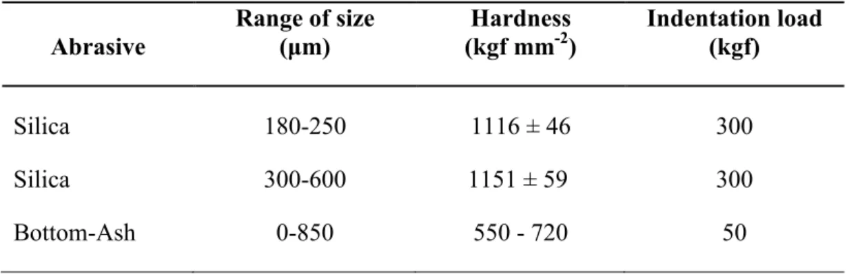
3.1.3 Characterisation of Abrasive Particles ... 84
3.1.3.1 Abrasive Materials ... 84
3.1.3.2 Analysis of Size ... 85
3.1.3.3 Morphology ... 85
3.1.3.4 Hardness ... 85
3.1.3.5 Fracture Strength ... 86
3.1.4 Characterisation of Worn Surfaces ... 86
3.1.4.1 Wear Scar Investigation ... 86
3.1.4.2 Profilometery Assessment ... 86
3.1.4.3 Temperature of Sample during Wear Testing ... 87
3.1.4.4 Particles Fragmentation Following Wear Test ... 87
3.2.5 Abrasive Wear Testing of Steel Substrates ... 88
4.2.5.1 Test Materials ... 88
4.2.5.2 Hardness Testing ... 89
3.1.6 Abrasive Wear Testing of Sprayed Coatings ... 89
3.2 Coating Properties and Characterizations ... 90
3.2.1 Materials ... 90
3.2.2 Spray Systems and Parameters ... 91
3.2.3 Characterisation of Powder Feedstock ... 91
3.2.3.1 Size Analysis ... 91
3.2.3.2 X ray Diffraction (XRD) ... 92
3.2.3.3 Scanning Electron Microscopy (SEM) and EDX Analysis ... 92
3.2.4 Characterisation of Coatings ... 93
3.2.4.1 XRD ... 93
3.2.4.2 SEM ... 93
3.2.4.3 Microhardness ... 93
3.2.4.4 Chemical Analysis ... 94
3.2.4.5 Phase Volume Fraction and WC Grain Size Analysis ... 94
3.2.4.6 Porosity ... 95
3.2.4.7 Fracture Toughness ... 95
Chapter 4 Abrasive Wear of Steel Substrates: Results and Discussion 4.1 Introduction ... 101
4.2 Results... 102
4.2.1 Characterisation of Abrasive Particles ... 102
4.2.1.1 Abrasive Materials ... 102
4.2.1.2 Morphology and Particle Size Analysis ... 102
4.2.1.3 Mechanical Properties ... 103
4.2.1.4 Particle Density ... 104
4.2.2 Characterisation of Steel Substrates ... 105
4.2.2.1 Analysis of Elements ... 105
4.2.2.2 Hardness ... 106
4.2.3 Characterisation of Wear Performance ... 106
4.2.3.1 Abrasion of Steels ... 106
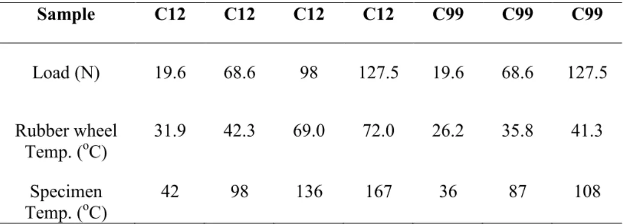
4.2.3.2 Temperature of Wear Samples during the Test ... 108
4.2.3.3 Particles Fragmentation during Wear Test ... 109
4.2.3.4 Particles in Contact Zone during Abrasion ... 111
4.2.3.5 Particle Loading During Abrasion testing ... 112
4.3 Discussion ... 115
4.3.1 Abrasive Wear of steels with Ash ... 115
4.3.1.1 Abrasive Particle Characteristics ... 115
4.3.1.2 Wear Behaviour ... 116
4.3.2 Abrasive Wear of Steels with Silica ... 119
4.3.2.1 Wear Rate and Mechanisms ... 119
4.3.2.2 Particle Motion during Abrasion ... 120
Effect of Sample Hardness ... 121
Effect of Applied Load ... 125
General Observations ... 127
4.3.2.3 Effect of Silica Particle Size and Shape on Wear ... 128
Chapter 5 Characterisation of Coatings: Results and Discussion 5.1 Introduction ... 158
5.2 Results... 159
5.2.1 Characterisation of Powders ... 159
5.2.1.1 Chemical Analysis ... 159
5.2.1.2 Morphology and Particle Size Analysis ... 159
5.2.1.3 Microstructure and Phase Analysis ... 160
5.2.2 Characterisation of As Sprayed Coating ... 161
5.2.2.1 Chemical Analysis ... 161
5.2.2.2 Microstructure and Phase Analysis ... 161
5.2.2.3 Mechanical properties ... 165
5.3 Discussion ... 165
5.3.1 Characterisation of Powders ... 165
5.3.2 Characterisation of As Sprayed Coating ... 166
Chapter 6 Abrasive Wear of HVOF Sprayed Coatings: Results and Discussion 6.1 Introduction ... 187
6.2 Results... 188
6.2.1 Characterisation of Abrasive Particles ... 188
6.2.1.1 Abrasive Materials ... 188
6.2.1.2 Morphology and Particle Size Analysis ... 188
6.2.1.3 Hardness ... 189
6.2.2 Characterisation of Worn Surfaces ... 189
6.2.2.1 Abrasion of Coatings ... 189
6.2.2.2 Wear Scar Investigation ... 191
6.3 Discussion ... 195
6.3.1 General Observations ... 195
6.3.2 Abrasive Wear with Silica ... 197
6.3.3 Abrasive Wear with Alumina ... 202
Chapter 7 Conclusions 7.1 Abrasion of Steel Substrates ... 236
7.2 HVOF Sprayed WC Cermet Coatings... 238
7.3 Abrasion of the WC Cermet Coatings ... 239
7.4 Industrial Aspects ... 242
Chapter 8 Future Work ... 244
References ..…………...……..……...……… 246
Nomenclature
Al aluminium
Al2O3 aluminium oxide (alumina)
APS air plasma spraying ARp particle aspect ratio
ASTM
the American Society for Testing and Materials at% atomic percent
BCC body centered cubic BOD ball on disc
BSE backscattered electron
C carbon
oC degree Celsius
Cermet ceramic metal composite C3H8 propane
CO carbon monoxide CO2 carbon dioxide
Co cobalt
Co I powder or coating of WC 17wt% Co with carbide size of ~1 Gm Co II powder or coating of WC 17wt% Co with carbide size of ~0.8 Gm Co III powder or coating of WC 17wt% Co with carbide size of ~0.5 Gm
Cr chromium
Cu copper
D Gun detonation gun
DSRW dry sand rubber wheel dp particle diameter
DWC tungsten carbide grain size
EDX energy dispersive X ray analysis FCC face centred cubic
Fe Iron
Fe (powder/coating) powder or coating of WC 15wt% iron alloy (FeCrAl) with carbide size of ~0.5 Gm
HCP hexagonal closed packed gf gram force H2 Hydrogen H hardness, kgf mm2 Ha abrasive hardness, kgf mm2 Hs surface hardness, kgf mm2 Hv Vickers hardness, kgf mm2
HVAF high velocity air fuel
HVOGF high velocity oxygen gaseous fuel HVOF high velocity oxy fuel
HVOLF high velocity oxygen liquid fuel
IRHD International Rubber Hardness Degrees
K Kelvin
kgf kilogram force KIC fracture toughness
kV kilovolt
λ binder mean free path
λ wavelenghth
LPPS low pressure plasma spraying
m metre
mA miliamper
M6C generic formula for eta carbides Co2W4C and Co3W3C
M12C generic formula for eta carbides Co6W6C
MPa megapascal where 1MPa = 1000000 Pa
N Newton
Ni nickel
Ni (powder/coating) powder or coating of WC 15wt% nickel alloy (NiMoCrFeCo) with carbide size of ~0.6 Gm
Q volume wear per unit sliding distance Ra mean roughness (Gm)
rpm revolution per minute
s second
SEM scanning electron microscopy SiC silicon carbide
SiO2 silicon oxide (silica)
TEM transmission electron microscopy Top Gun a type of HVOF gun
VfCo cobalt volume fraction
VfWC tungsten carbide volume fraction
VPS vacuum plasma spraying Vol% volume percent
W total applied normal load, N
W tungsten
WC tungsten carbide W2C di tungsten carbide
WC Co tungsten carbide with cobalt binder wt% weight percent
XRD X ray diffraction XRF X ray fluorescence
Chapter 1
Introduction
Wear occurs in many different industrial situations, and results in high costs due to equipment failure, replacement of wear parts and downtime during repairs. In addition, wear may influence the quality of the products involved. Wear is defined as the progressive removal of material from a surface due to mechanical movement with or without chemical processes. Among the various wear mechanisms, abrasive wear is the most important one due to its destructive character and its high occurrence frequency 50% of total wear failures [1]. In abrasive wear, detachment of material from surfaces in relative motion is caused by hard particles between the opposing surfaces or fixed in one of them. Its control and minimisation depends essentially on not only the appropriate selection of materials, but also understanding the mechanisms which are responsible for the abrasive wear of these materials.
Due to its importance, much work has been conducted in the area of abrasive wear and a correspondingly large number of test methods have been used to evaluate abrasion resistance of materials. Often, test apparatus are designed with a specific service application in mind [2]. Test methods can be broadly divided into those
where the abrading medium is loose as it passes over the testpiece (commonly termed three body abrasion) and those where the abrading medium is fixed in orientation as it passes over the testpiece (commonly termed two body abrasion) [3]. The most commonly employed test setup for three body abrasion is that encompassed in the ASTM standard G65 [4], commonly known as the dry sand– rubber wheel (DSRW) test (Fig. 1.1). In this test, a stream of particles is fed through the loaded contact between a test specimen and a rotating rubber wheel; the abrasive particles pass through the contact region once only. Since the rubber wheel rotates and the abrasive passes through the gap, it is clear that no permanent embedment of the particles onto the sample surfaces can take place. Instead a particle can traverse through the contact either by rolling or by becoming temporarily embedded into the rubber wheel and being dragged through and forming a groove in the metal sample as it does so.
The DSRW test has been employed to examine the abrasion behaviour of a very wide range of materials. In many programmes, the test is used simply to provide a quantitative ranking of the abrasion resistance of different materials. For example, the behaviour of a series of steels with a wide range of hardness has been tested, and whilst good correlation was found between wear rates and hardness, the operative mechanisms of wear were never examined [5, 6].
In DSRW abrasion, the operative mechanisms of wear depend largely upon the material properties (e.g. hardness, ductility, toughness) along with the manner in which the particles move through the contact between the wheel and specimen. The particles may embed into the moving rubber wheel and slide across the
sample material through the contact region (generally termed two body abrasion) or pass through the contact region by rolling between the rubber wheel and the sample (generally termed three body abrasion). Whilst it has been recognised that the manner in which the particles move through the contact affects the mode of wear and thus ultimately the rate of material removal, the motion of particles through the contact zone has itself been shown to depend upon a number of parameters associated with the system, amongst them particle shape, applied load and the hardnesses of the test surface and counterbody [7 9].
However, despite the recognition of the critical role of the particle motion in controlling the mode and thus (potentially) the rate of abrasive wear, surprisingly little work has examined the basic mechanics of the particle motion in the DSRW test. In a few papers, models to describe the motion of individual particles have been formulated and presented, which examine the moments upon such particles during a test [8, 10]. The model of Fang et al. [10] considers the motion of a particle in terms of the turning moment acting upon the particle; the simplicity of this model makes it useful for studying the effects of various external parameters on particle motion.
In the first part of this work, two investigations on the abrasive wear behaviour of steels using the DSRW test are carried out; firstly, the abrasion of three steels with an ash from a biomass power station are compared with that observed for abrasion with a conventional silica abrasive. In the burning of biomass in thermal power stations, ash is produced which commonly leads to damage of the powerplant through a combination of abrasion, erosion and corrosion [11] and can be
considered as an abrasive media. The aim of this investigation is assessment of wear behaviour of this type of ash in order to reduce its harmful effects on the powerplant components. The second investigation is a study on the motion of particles in the DSRW test with silica abrasive against a range of steels, both as a function of applied load, but also as a function of the hardness of the steels. The changes in behaviour are rationalised in terms of the mechanics governing particle motion. The aim of this work is achievement of a robust model in order to describe the motion of particles in contact in DSRW test which addresses the detail of the particle rubber wheel contact mechanics.
Most engineering materials used for applications in which abrasive wear resistance is a major requirement, such as tool steels, white cast irons, cobalt based alloys and metallic matrix composites, are multiphase materials formed of a metallic matrix reinforced by a dispersion of hard particles [12]. The reason for the success of this type of material in tribological applications can be explained, in a simplified form, by stating that the toughness of the matrix together with the hardness of the reinforcement particles enables optimal wear resistance to be achieved. The abrasive wear resistance of materials consisting of mixtures of hard and soft phases depends on several microstructural parameters, e.g. hardness, shape, size, volume fraction and distribution of the hard phase particles, the properties of the matrix and the interfacial bonding between the two phases. They are composite materials with a hard phase, normally WC that has a hexagonal crystal form and a binder phase which is normally cobalt. To increase the corrosion resistance of the materials other metallic or alloyed binders such as nickel are used.
The characteristic high hardness and fracture toughness of sintered WC cermets has made them materials of choice for use as abrasive wear resistant components in a variety of industrial applications. These composites combine the hard, brittle WC phase and a ductile metallic binder phase in different proportions to produce materials with a wide range of properties [13]. Tungsten carbide grain size distribution, as well as the content and composition of the cementing metal binder phase, play a decisive role in determining the fracture mode, mechanical properties, and wear resistance of these materials [14, 15]. Studies of WC Co materials have shown that abrasion typically involves rounding, fragmentation, and pullout of WC grains and removal of exposed binder, and have suggested that the material removal process involves both plastic deformation and fracture [16, 17].
An alternative to the use of wear resistant bulk materials is surface engineering to produce materials that are wear resistant, with the objective of maximising the benefit cost relationship Surface engineering aims to produce composite materials where the substrate and the coating or surface modification provide superior performance to that which would be obtained by each of the parts individually. The performance obtained is always a combination of various physical, chemical, mechanical, metallurgical and thermal properties of the substrate and coating. In this context, the use of high velocity oxy fuel HVOF thermal sprayed WC cermet deposits looks promising for wear protection due to the excellent combination of mechanical properties of these cermets [18].
HVOF spraying is one of many processes used for spraying coatings with tribologically attractive properties. In this process, the combustion reactions between oxygen and a fuel propel particles at high temperature and high velocity towards the substrate. The coatings produced have low porosity, high adhesion to the substrate and low oxide content due to the high velocities used The coating is formed by particles of liquid and or mushy materials that strike against the substrate where they form thin platelets called lamellae or ‘‘splats’’, which cover the surface irregularities. The lamellae cool rapidly depending on the thermal spray process used, and solidify. Other particles that are projected over the already deposited material acquire the same lamellar shape, forming anisotropic structures parallel to the interface. The result of such a deposition process is a coating with a structure of splats, voids and oxides.
The properties and performance of WC cermet coatings are attributed to a complex function of size, shape and distribution of carbides, hardness and toughness of matrix, binder matrix composition and content, and microstructural changes which occur during the spray process. The investigations of the causal relationship between deposition process parameters, microstructure and wear performance have shown that to reach the best output, the coating should have high retained WC content which is finely dispersed [19, 20]. This depends essentially on minimising decarburisation and dissolution of WC during spraying, which is a function of the powder characteristics, flame temperature and particle velocity. The tungsten and carbon from the dissolving carbides diffuse into the matrix and react with binder and promoting the formation of amorphous phases that are hard and brittle. This change to the microstructure of the matrix has a
significant effect on the coating properties [19, 20]. These reactions have generally a negative effect on coating performance in wear.
In recent decades, the processing, properties and applications of the WC Co coatings with different cobalt content have been extensively studied. There are also a considerable works on the characterisation and properties of thermally sprayed WC cermets with other binders such as CoCr and Ni. However, there is little information in the literature about the new WC cermet coatings with complicated alloyed binders (e.g., nickel base and iron base alloys) and their wear behaviour, especially in relation to abrasive processes. Therefore, the second part of this investigation focuses on characterisation and three body abrasion of WC– NiMoCrFeCo and WC FeCrAl coatings which were deposited using a Top Gun HVOF system. For comparison, three types of the WC 17 wt% Co powder feedstocks with different carbide grain sizes were also deposited. The aim of this study is characterisation of the new WC coatings (i.e. WC composite coatings with Ni base alloy and Fe base alloy binders) and their abrasive wear behaviour under “hard abrasion” and “soft abrasion” regimes.
This thesis comprises eight chapters. Chapter 2 presents a review of the literature about the main subjects presented in this thesis. In chapter 3 the methodology and the experimental equipments and materials which are utilised are described. Chapter 4 includes the results and discussion of abrasive wear of steel substrates whereas chapters 5 and 6 present results and discussions of the characterisation of the coatings and their abrasive wear behaviour respectively. The conclusions and future work are presented in chapters 7 and 8.
Chapter 2
Literature Review
This chapter presents a review of the literature about the main subjects presented in this thesis. Keeping in view the themes of the thesis, the chapter is divided into following main parts; i) Abrasive Wear and ii) HVOF Sprayed WC Cermet Coatings. Section 2.1 addresses abrasive wear process in general followed by reviews of abrasive wear in steels, abrasive wear ash from power plants and abrasive wear in WC cermet materials and coatings. Section 2.2 comprises a brief background to HVOF process, WC cermet materials, and microstructural developments during spraying of these materials.
2.1
Abrasive Wear
2.1.1
Introduction
In general, wear may be defined as the progressive loss of material from a solid surface by the mechanical action of a contacting solid, liquid, or gas [21]. Many wear studies have focused on surface damage in terms of material removal mechanisms, including transfer layer formation, plastic deformation, brittle fracture and tribochemistry [22]. Wear has been classified in various ways; one of the usual classifications of wear is based on the fundamental mechanism that is operating. Wear can be divided into different modes such as adhesion, abrasion, erosion, surface fatigue and tribochemical reaction. Each wear mode can also be
behaviour of materials, a specific mechanism of material removed may be dominant; however, commonly, several wear mechanisms operate at the same time [23].
Wear occurs in many different industrial situations, and results high costs due to equipment failure, replacement of worn parts and downtime during repairs. In addition, wear may influence the quality of the products involved. The cost of wear is high; findings have shown that the cost of wear to the U.S. economy was about $20 billion in 1978 [24].
2.1.2
Types of Wear
Wear encountered in industrial situations can be broadly grouped as: abrasive 50%, adhesive 15%, erosion 8%, fretting 8%, and chemical 5% [1].
Abrasive Wear
Abrasive wear is the displacement or detachment of material by the passage of hard particles or hard bulges which are forced against and slide along a solid surface [16]. In this type of wear, a material is seriously abraded or scratched by a counterbody harder than itself. Under a normal load, the asperities on the harder surface indent into the softer surface thus, producing plastic deformation. When a tangential motion is introduced, the material is removed from the softer surface by the combined action of micro ploughing and micro cutting.
This type of wear occurs due to localised bonding or welding between contacting solid surfaces leading to material transfer between the two surfaces and loss from either surface.
Fatigue Wear
Fatigue wear of a solid surface caused by fracture resulting from material fatigue. This wear is caused by deformation sustained by the asperities and surface layers in contact. Contact between asperities accompanied by very high local stresses generate fatigue propagated cracks, hence the term fatigue wear [25].
Erosive Wear
This type of wear occurs when individual solid particles impact with a surface. This wear is defined as the process of material removal from a surface subjected to impingement attack by solid or liquid media, being particulate in nature for the former and in the form of droplet for the latter [21]. In erosion, several forces of different origins may act on a particle in contact with a solid surface [25].
Fretting Wear
Fretting wear is defined as a type of wear which occurs as a result of slip by a small amplitude of two surfaces relative to each other. Like all tribological systems, the surfaces are loaded. As the amplitude is increased the material losses by fretting tend to be similar to that due to reciprocating sliding under comparable conditions of load and environment [21].
Chemical or corrosive and oxidative wear occur in a wide diversity of situations with both lubricated and unlubricated surfaces. The main cause of this form of wear is a chemical reaction between the wearing material and a corroding medium which can be a chemical reagent, reactive lubricant or even air. This type of wear occurs when a film of material is formed by chemical attack of either contacting body and while this may provide some lubrication, this film is commonly readily removed by the mechanical action associated with one of the other mechanisms of wear [25].
2.1.3
Abrasive Wear Processes
The abrasive wear process has been classified according to three factors [26]:
• The number of bodies involved in the contact, two or three body;
• The stress level; low if the abrasive does not fracture significantly and high if it does;
• Freedom of the abrasive; open if the abrasive is free to move in the direction of the normal load, closed if it is constrained.
Classifications such as two body and three body, high and low stress conditions have been developed over the years to describe abrasion processes in order facilitate meaningful discussion [27].
2.1.3.1
Two and Three body Abrasion Wear
In abrasive wear, material is removed or displaced from a surface by hard particles, or sometimes by hard protuberances on a counterface (hard rough surface), forced against and sliding along a soft surface [3]. The nature of abrasive wear is determined by the way which particles traverse the worn surface. Particles
may roll and/or slide over the surface (Fig. 2.1). Therefore two basic modes have been identified: two body and three body abrasive wear.
Two body abrasive wear involves the removal of material by abrasive particles which are held fixed (as in abrasive paper) while being moved across a surface. This process produces a grooving form of wear.
Three body abrasion involves loose particles which may rotate as well as slide as they contact the wearing surface. Compared to two body abrasion, three body abrasion is much more common and also much more complicated than two body abrasion. Plastic indentation wear will be much more important in three body abrasion than that in two body abrasion [28]. Furthermore, in three body abrasion, the movement patterns of abrasives are more complicated than in two body abrasion, since the abrasives not only slide, but also roll. Thus, a relatively wide range of wear rates have been variously reported for three body abrasion conditions, which depend not only on the material being tested, but also on the testing apparatus. In three body abrasion of metals, cutting wear and plastic deformation wear coexist [29]. As a consequence, two body abrasion tests are said to produce wear rates one to three orders of magnitude higher than three body abrasion under comparable loading conditions [30, 31].
2.1.3.2
Open and Closed Abrasive Wear
Misra and Finnie [32] proposed a further subdivision of three body abrasion into “closed” and ”open” groups. The closed group covers the cases of fine abrasives between closely mating surfaces. Open three body abrasion covers cases where
there is a thick bed of abrasive, or the particles are so large, that the two opposed surfaces are so far apart that the mechanical properties of one have no influence on the other.
2.1.3.3
High and Low stress Abrasive Wear
Abrasive wear processes have also typically been grouped into two regimes: high or low stress [2]. When abrasive particles are compressed between two solid surfaces, high stress or grinding abrasion occurs. The high pressure produces dents and scratching of the surfaces and fractures and crushes the abrasive particles [33]. Low stress or scratching abrasion happens when lightly loaded abrasive particles move across the wearing surface, generating cutting and ploughing on a microscopic scale but with no damage to the abrasive particles. The distinction between low stress and high stress conditions is not sharp [27].
2.1.4
Mechanisms of Abrasive Wear
Several mechanisms have been proposed to explain how material is removed from a surface during abrasion. These mechanisms include plastic deformation, fracture, fatigue, grain pull out and corrosion [3, 23, 25, 34]. In order to understand abrasive wear in simple terms, these mechanisms shall be separated into the two main mechanisms: plastic deformation and fracture (Fig.2.2). Under some circumstances, plastic flow may occur alone, but because of the complexity of abrasion, rarely does one mechanism completely account for all the loss. Although the plastic deformation mechanism is often linked with ductile materials
and the fracture mechanism is linked with brittle materials, both can occur together.
2.1.4.1
Plastic Deformation
Two major processes take place when abrasive particles contact the surface of a relatively ductile material [34]:
• The formation of grooves which do not involve direct material removal.
• The separation of material in the form of primary wear debris or microchips.
In both cases, material is deformed to the side of the grooves and can become detached to form secondary microchips. Ultimately, material is removed by fracture, but plastic deformation processes control the rate at which material is removed. If fracture did not occur, the material would continue to deform until it was able to elastically support the load on the contacting particles.
Robinowicz suggested a simple model for the abrasive wear process by plastic deformation [35]. This model is based on an abrasive particle, idealized as a sharp cone of semiangle θ, being dragged across the surface of a ductile material which flows under an indentation load F (Fig. 2.3). It forms a groove in the material with hardness H, and wear is assumed to occur by removal of some proportion of the material which is displaced by the particle from the groove. The volume of groove V per unit length can be obtained:
H F L V θ πtan 2 =
(2.1)
H F K
Q= (2.2)
which is the well known Rabinowicz equation [31]. K is the wear coefficient and defined as: θ π η tan 2 = K (2.3)
where η is the fraction of material displaced from the groove. According to the Rabinowicz model, wear in homogeneous materials only depends on the attack angle θ, the normal load F, the hardness H of the material and the geometry of the indenter (in this case a conical indenter). This simple model suggests that the wear rate per length of sliding will be directly proportional to the load, and will vary inversely as the hardness of the surface.
2.1.4.2
Fracture
Although plastic deformation occurs during abrasive wear of brittle materials, fracture is often the rate controlling mechanism. Even during the wear of ductile materials, fracture may occur. For a ductile material, fracture is most likely to occur just behind a contacting abrasive particle since this region is subject to a tensile stress. The material removal in brittle materials is likely to be controlled by fracture rather than by plastic deformation except during wear by very lightly loaded blunt abrasive particles [36].
One model for the abrasive wear by fracture is based on the removal of material by lateral cracks which grow upwards to the free surface from the base of the subsurface deformed region and are driven by the residual stresses associated with
the deformed material (Fig. 2.4). Evans and Wilshaw developed a model using fracture mechanics to describe removal of material by lateral cracking [37]. In this model, the volume wear rate per unit sliding distance Q is given by:
2 1 4 3 4 1 2 1 4 5 H K A d F Q C α = (2.4) where F, d, A, Kc and H are load, diameter of abrasive particle, contact area,
fracture toughness and hardness of material respectively. α is a material independent constant.
2.1.5
Variables Affecting Abrasive Wear
There are several factors which influence the wear of material during the abrasive wear process. These factors can be grouped under three main headings; particle, material and environment.
2.1.5.1
Properties of the Particle
Geometric properties (Particle shape, orientation and size)
Both theoretical predictions and experimental results confirm that the abrasive particle shape has an effect on the rate of wear [38]. This is because it influences the transition load from elastic to plastic contact and the critical indentation size for fracture. If particle load and surface hardness are constant, the projected area of plastic contact will be constant, but the cross sectional area of a groove resulting from such a contact will depend on the particle shape. Moore showed that the ratio of cross sectional to projected area of contact for pyramidal, conical and spherical indenter increase as the included angle, cone angle and radius,
respectively, decrease [39]. In addition, this ratio is generally less for a spherical than for a pyramidal or a conical contact. Thus, for both plastic and brittle mechanisms of material removal, it is expected that the wear rate will be higher for “sharp” pointed abrasives than for “blunt” round abrasives [40]. Fig. 2.5 shows a comparison of the wear rate obtained in abrasive wear testing for steel against two types of abrasive sands namely rounded and crushed silica sands. Both sands had the same particle size distribution and differed only in their shape. The sharp, crushed particles resulted in rates of wear typically two to five times higher than that produced by their rounded counterparts. Swanson and Klann [41] have reported a factor of ten in the volume loss of the plain carbon and low alloy steels examined using the wet and dry sand rubber wheel abrasion tests with round and angular silica abrasives.
The abrasive particle size also affects the wear rate of materials. When the materials and the abrasive type remain fixed, the wear rate increases with increasing particle size up to a certain size; above this critical size, the wear rate becomes almost independent of further size increases. This critical size is often cited as about 100 Gm (Fig. 2.6) [42].
Particle Hardness
The hardness of abrasive particles can influence the rate of wear. Particles with lower hardness than that of the surface cause much less wear than harder particles. It has been found that the rate of material removal decreases significantly when the hardness of the surface Hs, approaches the hardness of the abrasive, Ha [43].
ceramics, abraded by two different types of abrasive particles. The wear rate becomes much more sensitive to the ratio of the abrasive hardness Ha to surface
hardness Hs when Ha/Hs is less than ~1. The critical value of Ha/Hs has in fact
been estimated as 1.2 [3, 44, 45]. Abrasive particles of any shape will cause plastic scratching only if Ha/Hs >1.2. Abrasion under conditions where Ha/Hs <1.2
is sometimes termed soft abrasion, in contrast to hard abrasion when Ha/Hs >1.2.
The critical transition point between hard and soft abrasion appears to be the point at which plastic deformation in the form of grooves and scratches occurs [46].
Particle Strength
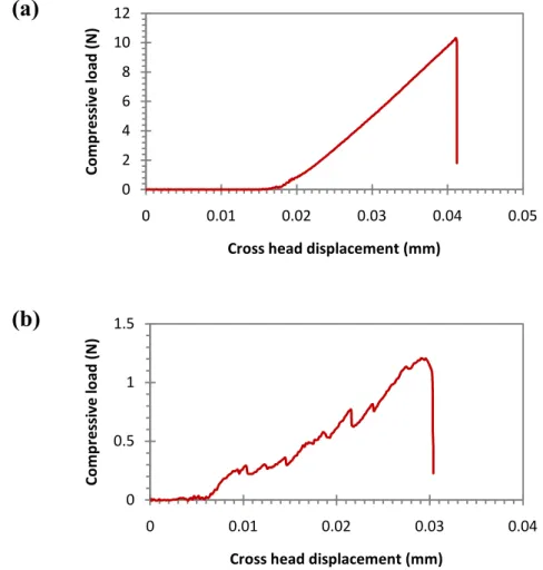
Plastic deformation of the surface will occur as the normal load on the particle is increased only if the particle can sustain this contact pressure without deforming or crushing. Thus, the strength and toughness of an abrasive particle are important factors in abrasive wear. Gahlin and Jacobson [47] described abrasive with quartz and chert, which have similar hardness, but with chert having a greater resistance to fracture than quartz; wear generated by chert was between two and three times that quartz.
2.1.5.2
Properties of the Material
Microstructure of the Specimen
The microstructure of materials affects their wear properties. For ferrous materials, various factors like retained austenite, carbide content and size, heat treatment regime and alloy content impact on the wear properties [48]. In heterogeneous materials like composites synthesized from two or more distinct components, the structural properties are important in abrasive particle contact.
Parameters such as volume fraction and distribution of a dispersed phase, its coherency and hardness all affect abrasive particle indentation, strain hardening, strain distribution, fracture, and recovery processes [49]. Fig. 2.8 shows that a finely dispersed hard second phase can result in homogeneous behaviour of a composite which leads, in general, to an increase in wear resistance.
Hardness of Specimen
The relationship between wear resistance and material hardness is complicated [9], but it is generally recognized that hard materials exhibit lower abrasive wear rates than softer materials. Eq. 2.2 suggests that the wear rate varies inversely with the hardness of the material. Many pure metals do behave in this way, although alloys often exhibit more complex behaviour (Fig. 2.9) [50]. The loss of proportionality between hardness and the relative wear rate for hardened metals is the result of defining the wear resistance in terms of the undeformed hardness of the metal [25]. The materials at the worn surface will have been strain hardened by plastic flow, and that hardness will generally be greater than that of the bulk. Moreover, the microcutting mechanism becomes more dominant as the hardness of the material increases. This was observed not only for abrasion with angular abrasives, but also for abrasives with a more rounded morphology [40].
2.1.5.3
Characteristics of the Test setup and Environment
Load
Eq. 2.2 predicts that the wear rate varies directly with the applied load. Although for many systems the wear rate varies proportionally with load over limited ranges, sudden transitions from low to high wear rate, (and sometimes back again)
are often found with increasing load associated with changes in mechanism of material removal [3, 51].
Temperature
The temperature of a wearing surface is controlled not only by the ambient temperature, but also by the heat generated (and carried away) by the wear process itself. The difference between those is that in the first, the abrasives remain relatively cool due to the transient nature of abrasion. During wear, a surface is subject to applied stress and temperature rises. At least 90% of the energy expended in plastic deformation during wear must be dispersed as heat [1]. The temperature increase caused by plastic deformation during abrasion is associated with the speed of sliding [52]. This may cause plastic deformation, recrystallization, and phase changes, all of which affect the mechanical properties of the surface material and, consequently, the abrasive wear rate. In general, with increasing temperature there is a corresponding decline in the hardness of both the worn material and the abrasive. Increasing temperature influences materials such as metals in decreasing their hardness more significantly than for the non metallic abrasive materials [53]. Therefore the ratio of abrasive hardness to metal hardness increases with increase in temperature leading to a higher wear rate. In addition, in three body abrasive wear, contact between an abrasive and the worn surface would be particularly short compared with that in the two body abrasive mode. Thus, in three body abrasion, heat generated in the deformed material would not easily diffuse into the abrasive particles. This causes thermal softening of the surface material while the abrasive remains with its hardness virtually unaltered [25]. Another effect of high temperatures is to induce a form of wear which
depends on the combined action of oxidation and removal of oxide layers by abrasion. The oxidation of steels in air is much more rapid at 600oC than at 20oC , and as temperature rises, the removal of steel as oxide becomes more significant [54].
Moisture
Moisture has a strong influence on abrasive wear rates. Usually, abrasive wear rates increase with moisture content in the atmosphere, but there are occasions when opposite effects have been observed [55]. The abrasive may either be just sufficiently weakened by moisture to produce a large number of new cutting edges, or severe grit weakening may occur causing disintegration of the grits into non–abrasive, fine particles. Both the worn material and the abrasive may be weakened by moisture [56]. Indeed, for the same abrasive and worn material, two body abrasive wear may increase with humidity while the three body abrasive wear rate may either increase or decrease [25].
2.1.6
Abrasive Wear Tests
2.1.6.1
Laboratory Abrasive Wear Tests
In selecting and specifying laboratory wear tests, attention must be paid to the fact that wear performance is system related, depending not only on materials properties but also on the characteristics of the abrasive and the sliding and loading conditions. There are two major groups of laboratory test methods for abrasive wear:
2 Those in which the abrasive is loose or free with respect to the wearing specimen.
In fixed abrasive tests, the type and size of abrasive is limited by the availability of bonded abrasive papers or cloths whereas in loose abrasive tests, there is (theoretically) complete freedom on the choice of abrasive which might even include abrasive material from a service environment. The load per unit area in some loose abrasive tests (particularly wheel tests and bin tests) is difficult to characterise and may vary widely throughout the duration of the test.
For fixed abrasive tests, the mechanics of abrasive particle wearing surface contact is consistent over a wide range of loading conditions and material types. This can vary with load, counterface properties, abrasive shape and test material. In attempting to devise or specify a laboratory test to simulate a service wear environment, the following system parameters should be considered [57]:
• Test conditions such as: Abrasive type, size, shape and distribution, fixed or loose abrasive, sliding distance, abrasive path length, sliding speed, load, and properties of counterface.
• Test materials such as: chemical/ physical/ mechanical properties and microstructural dimensions of materials.
2.1.6.2
Standard Test of Abrasive Wear
It is important to thoroughly characterize the test conditions, to determine the precision of the test technique, and to consider these as the results are interpreted. Reproducibility (an essential feature of any good test) can be achieved by careful
control of variables. The most commonly used laboratory tests for abrasive wear employ either a pin shaped specimen sliding against fixed abrasive giving two body wear (Figs. 2.10a to 2.10c), or a rotating (rubber or steel) wheel sliding against a plane specimen with loose abrasive particles being continually fed between the two, giving three body wear (Fig. 2.10d).
Typical laboratory abrasive wear tests are [31]:
1. Dry/wet sand rubber wheel three body (low stress) abrasion; 2. Dry/wet sand steel wheel three body (high stress) abrasion; 3. pin on drum two body (high stress) abrasion;
4. Jaw crusher (high stress) gouging abrasion; 5. High speed, impeller–tumbler impact abrasion.
The dry sand rubber wheel (DSRW) abrasion test apparatus has been used widely to simulate low stress, three body abrasive wear [58]. The pin on drum abrasive wear test (POD) involves high stress, two body abrasive wear. The jaw crusher test is a type of high stress wear test that may result in either two body or three body conditions [59].
2.1.6.3
Dry Sand Rubber Wheel Test
The most commonly used test configuration for three body abrasion is that of a specimen loaded against a rotating wheel with abrasive particles being entrained into the contact zone. This is the basic principle of the tests described by ASTM standard G65 [4]. The rubber wheel tester, which was standardized by ASTM, has been said to produce low stress three body abrasion [5]. Even before the test
became an ASTM standard, it had been used by a number of laboratories for many years. The test is widely used to rank materials for components that will be subjected to low stress abrasion in service like agricultural tools, chutes and hoppers in ore processing plant, and construction equipment [60]. This test has a longer history, and has generated more data than other types of abrasion testing machines [61]. However, this test configuration has some limitations. For example, the abrasive particles may get embedded in the rubber wheel and scratch the test specimen in a manner similar to two body abrasion [2].
The apparatus is shown schematically in Fig. 2.11. In the test, a plane specimen is loaded against the rim of a rotating rubber wheel; sand is fed into the gap between the wheel and specimen and is carried past the specimen and thus abrades it. The behaviour of a material in a rotating wheel abrasion test depends not only on the intrinsic properties of the test sample itself, but also on the conditions of the test, such as nature of the abrasive particle type, size, shape, brittleness, the wheel hardness, its stiffness and the nature of the environment. The rubber wheel abrasion test has been the subject of a large body of research [62].
2.1.6.4
Rubber Wheel Variables
In the sand rubber wheel test, the rate of wear increases with rubber hardness, which is measured with a Shore A Durometer tester, as described in ASTM D 2240 [4]. It has been shown that the weight loss of some steels exhibits an exponential dependence on the rubber hardness (Fig. 2.12). This function could be linearized by means of a semi log plot (Fig. 2.13). The plot represents results in the form of parallel straight lines displaced in a vertical direction. The effect of
rubber wheel hardness on wear rate can be explained in the way that particles groove or roll. It has been also suggested that the hard wheel tends to distribute the total load only over the largest grains, with particles too small to be loaded by the rubber probably being ineffective (Fig. 2.14) [62].
Avery [62] used concept of “opportunity vs. severity” to explain the independence of the wear rate on the sand feed rate. Sand feed rate is partly opportunity, but it also affects severity, and thus would not be altered to merely change weight loss. In a low feed rate condition, a few particles are in contact between the rubber wheel and the surface resulting in high load per each particle, whereas in the high feed rate of abrasive, a large number of articles are in contact causing a low load per particle. Therefore, the wear rate is independent of feed rate of abrasive [63]. The Rabinowicz [35] wear model (Eq. 2.2) show two wearing parameters (F and H) that are obvious and others are concealed in the wear coefficient ,K , which has been given a physical definition but actually is a factor of ignorance.
It has been found that the velocity of the wheel (sliding speed) only slightly affects the wear rate. This is thought to be due to surface temperature changes. Stevenson and Hutchings [63] remark that in the rubber wheel dry sand abrasion test, the observed dependence of wear rate on sliding speed is more probably related to variations in the mechanical properties of the rubber with strain rate and temperature than with the properties of the test material. As the temperature of the rubber increases, its hardness declines (Fig. 2.15). A maximum was seen in the dependence of wear rate on sliding speed. This was attributed to a balance
between strain rate effects increasing the modulus of the rubber, and heating effects reducing the modulus.
2.1.7
Abrasive Wear Behaviour of Steels
Many investigators [1, 50, 64] have shown that the abrasive wear resistance of steels increases with carbon content and with increase in hardness due to heat treatment. Studies also show that the wear behaviour of steels greatly depend on their microstructural features. The nature of phases present such as pearlite and martensite and changes in volume fraction of martensite in a ferrite matrix (dual phase structure) have been observed to strongly control the overall wear response [48]. Fig. 2.16 shows that the abrasive wear ratio is a strong function of the carbon content and microstructure within a range from 0 to 0.8 wt%. However, the wear resistance does not increase with any hardening associated with work hardening [65]. Fig. 2.17 shows that the wear resistance of steel increases rapidly only when the surfaces being abraded exceeds some critical ratio of the hardness of the abrasive. Moreover, there is a direct correlation between carbide volume fraction in steels and their resistance to abrasive wear in which the wear rate of steel decreases as the carbide content increases [34]. Swanson and Klann [41] showed that the use of an angular abrasive produces a significant increase in the volume loss of the plain carbon and low alloy steels examined. The shape of the abrasive certainly is a significant factor; however the change in the number of particles that slid across the interface when the abrasive is changed from a round grain to a sharp grain sand is also a contribution factor to take into account.
2.1.8
Abrasive Wear with Ash Particles
2.1.8.1
Introduction
Due to sanitary and environmental problems and operational costs related to either the discharge, land disposal or re use of wastes, the utilization of biomass as a fuel is significant issue [66, 67]. It is found that different types of biomass materials have a high heat content which can be classified as carbon neutral energy content. Therefore as a renewable energy source, it can be employed for firing in power plants [68]. Recently its use as a fuel source for thermal power plants has increased, both as a main fuel, and for co firing with coal.
In combustion processes, ash is produced in the form of fly ash and bottom ash. Both types of ash particles can result in mechanical and chemical damage to the related components. Depending on the system, this damage may be erosion or abrasion; and it may be complicated by corrosion [11].
There is a wide range of feedstock materials which are termed “biomass”; the ash produced from them is also different. The behaviour of the ash associated with these types of fuel sources is of concern, particularly in terms of their abrasiveness [66]. Ash associated with conventional coal burning plants has been seen to lead to significant abrasive wear of components of the power plant [69].
2.1.8.2
The Ash Originating From Combustion
During combustion, the mineral matter present in fuels may undergo chemical changes, such as oxidation, loss of water of crystallization, decomposition of the
less stable compounds, and calcination of carbonates to oxides. It may also undergo physical changes: some particles may melt, others may soften allowing rounding the corners of the particles, and the mineral within the coal and biomass material may accrete during the combustion of the particles to form hollow spheres (agglomeration) [67]. The extent of these changes will depend on the combustion process itself, and in particular on the maximum temperature attained and the residence time of the mineral matter in the hot zone. Some of the ash may be present as large particles; some of it may form a liquid slag which may freeze on cooler parts of the system and eventually separate as large fragments. These parts of the ash generally fall to the bottom of the combustion system, where they are removed: collectively they are referred to as bottom ash. Other parts of the ash are present as relatively small particles, and are carried along with the combustion gas as it flows through the system. This is called the fly ash. The chemistry of the bottom ash and the fly ash may be different; the relative amounts depend on the chemistry of the mineral matter in the fuel, and on the detailed characteristics of the combustion system. The wastage process may involve both mechanical effects and chemical effects. The mechanical effects include erosion, (which involves the impact of particles on the wasting surface, with the particles moving freely before and after the impact) and abrasion (where the particles are loaded onto the surface and move in contact with it for some time) [11].
2.1.8.3
Coal Ash
The coal used in thermal power plants for generating electricity may result in 30 to 40% ash and even more [70]. About 80% of the ash is entrained in the flue gas
bottom ash, a dark gray, granular, porous, predominantly sand sized (< 12.7mm) material that is collected in a water filled hopper at the bottom of the furnace [71]. The coal ash itself is extremely abrasive. The aggressive nature of this mixture leads to rapid wear of the components. The mechanism of wear has been found to be a combination of corrosion and abrasion acting synergistically [69]. The fly ash particles can result in mechanical damage to the boiler tubes [11] whereas bottom ash generated from fluidized bed combustion (FBC) boilers causes significant wear in ash cooling screws (Fig. 2.18) [72].
2.1.8.4
Biomass Ash
The wear of the equipment in power plants is associated with the hard particles present in the fuel and ash, particularly those that are harder than the steels and other materials which are used for construction. The only mineral species that is commonly found in clean biomass materials in significant levels which is in this category is quartz, and only high quartz biomass materials or those contaminated with significant levels of tramp materials are expected to present problems with erosion and abrasion in the fuel handling and firing equipment [73].
In general, biomass usually creates less ash than coal, and the composition of its ash tends to reflect the inorganic material required for plant growth [74]. For this reason, wear processes tend to be less important than they are in coal fired plants. There are however, some specific areas where wear can be significant issues:
• Some biomass materials such as rice husk have high quartz content [66].
• The formation fused ash materials, particularly the bottom ash from grate fired systems.
• In biomass boiler systems which suffer severe convective section fouling problems, there are excessive rates of particle impact erosive wear of boiler tubes and erosive wear associated with the regular use of convective pass soot blowers [73].
2.1.8.5
Abrasive Testing of the Ash
Characterization of the abrasive wear resistance of the components against ash is best achieved by loose abrasive testing, in which the particles are free to roll and or reorient themselves as they pass across a wearing surface. The most common tests which fall into this category utilize either the wet sand or dry sand rubber wheel abrasion tests.
2.1.9
Abrasive Wear of WC Metal Coatings
2.1.9.1
Introduction
The abrasive wear properties of WC–Co composites in the coated [20, 75 80] and sintered [81 84] forms have been extensively studied for the last two to three decades in light of their high resistance to wear. There is also a large body of work on WC cermets with other metallic binders such as Ni and CoCr [85 89] which are used in order to improve the corrosion resistance of these materials. In many of these works, research has sought to compare the behaviour of sintered and sprayed WC cermet systems to understand the microstructure–performance relationships, to enable the performance of coated systems to be improved towards that of sintered materials.
2.1.9.2
Abrasive Wear of Sintered WC Metal Cermets
Because of a favourable combination of hardness and toughness, cemented tungsten carbides are commonly used in applications where the material is exposed to abrasive wear conditions such as in cutting tools [90]. The abrasive wear resistance of materials consisting of mixtures of hard and soft phases depends on several microstructural parameters such as hardness, shape, size, volume fraction and distribution of the WC grains, the properties of the matrix and the interfacial bonding between the two phases [91]. The mechanism of abrasion depends on the hardness ratio of the abrasive particle and the cermet which controls the resistance of the cermet to penetration by the abrasive particle [82]. Studies of WC cermets have shown that abrasion typically involves rounding, fragmentation, and pullout of WC grains and removal of exposed binder, and have suggested that the material removal processes involve both plastic deformation and fracture [17].
Wear Mechanisms
The mechanism of abrasion in ductile materials is plastic deformation (section 2.2.4.1) while for brittle materials such as ceramics, it is dominated by fracture (section 2.2.4.2). Cemented WC cermets made up of two distinct hard and soft phases are more complex than homogeneous materials and it has been shown that their abrasion typically occurs by different mechanisms and at different rates, depending on the hardness ratio of abrasive and cermet [17]. If the abrasive hardness Ha is more than 20% harder than the cermet hardness Hc, it is termed a
removed by plastic deformation and grooves formed in the surface. Surface deformation is primarily by plastic flow, assisted, occasionally, by microfracture in the binder phase. The scale of each removal event is typically one or more orders of magnitude greater than the WC grain size and bulk hardness is the property which best correlates with resistance to abrasion in this region of abrasion by relatively hard abrasives [92]. Relatively soft abrasives, on the other hand, give a much reduced rate of wear and the mechanism of material removal is preferential removal of the binder followed by fragmentation and pullout of carbide grains [44, 93].
Jia and Fischer [94] investigated wear behaviour of cemented WC Co cermets under hard and soft abrasion. Under a hard abrasion regime, their results showed that material was being removed by plastic deformation of the binder and fragmentation of the WC grains. Moreover, the fracture resistance of WC grains increased with decreasing grain size. Under soft abrasion, low penetration of the abrasive particle in to the cermet without clear grooving was observed, but instead binder removal was observed which left exposed WC grains which themselves were removed by cracking or pull out. It was also found that the abrasive wear resistance increased sharply with cermet hardness. They suggested that dependence of abrasion on the local fracture strength and therefore carbide grain size under the soft abrasion was less than that under the hard abrasion.
Larsen Basse and Koyangi [44] studied what they termed the scale effect in cemented WC Co cermets. They concluded that an abrasive particle like silicon
![Fig. 2.7 Relative abrasive wear resistance versus hardness ratio of worn to abrasive material [34]](https://thumb-us.123doks.com/thumbv2/123dok_us/1394045.2686704/83.892.361.614.108.469/relative-abrasive-resistance-versus-hardness-ratio-abrasive-material.webp)
![Fig. 2.13 Weight loss of various materials as determined from the rubber wheel abrasive test at different levels of rubber hardness [61]](https://thumb-us.123doks.com/thumbv2/123dok_us/1394045.2686704/85.892.341.633.108.471/weight-various-materials-determined-rubber-abrasive-different-hardness.webp)


![Fig. 4.1 SEM morphology images of the abradants employed for abrasion testing on steels; (a) bottom ash 0 850]m; (b) silica sand 180 250 ]m; (c) silica sand 300 600 ]m](https://thumb-us.123doks.com/thumbv2/123dok_us/1394045.2686704/148.892.320.662.117.970/morphology-images-abradants-employed-abrasion-testing-steels-silica.webp)