Protocols and Practice
Release 0.25
Olivier Bonaventure
Information on The Saylor Foundation???s Open Textbook Challenge can be found at www.saylor.org/otc/.
Universit?? catholique de Louvain for teaching Local Area Networks. After The Saylor Foundation accepted
his submission to Wave I of the Open Textbook Challenge, this textbook was relicensed as CC-BY 3.0.
1 Preface 3
2 Introduction 5
2.1 Services and protocols . . . 11
2.2 The reference models . . . 20
2.3 Organisation of the book . . . 25
3 The application Layer 27 3.1 Principles . . . 27
3.2 Application-level protocols . . . 32
3.3 Writing simple networked applications . . . 55
3.4 Summary . . . 61
3.5 Exercises . . . 61
4 The transport layer 67 4.1 Principles of a reliable transport protocol . . . 67
4.2 The User Datagram Protocol . . . 87
4.3 The Transmission Control Protocol . . . 89
4.4 Summary . . . 113
4.5 Exercises . . . 114
5 The network layer 127 5.1 Principles . . . 127
5.2 Internet Protocol . . . 140
5.3 Routing in IP networks. . . 170
5.4 Summary . . . 195
5.5 Exercises . . . 195
6 The datalink layer and the Local Area Networks 211 6.1 Principles . . . 211
6.2 Medium Access Control . . . 214
6.3 Datalink layer technologies . . . 228
6.4 Summary . . . 246
6.5 Exercises . . . 246
7 Glossary 249
Bibliography 259
Preface
This textbook came from a frustration of its main author. Many authors chose to write a textbook because there are no textbooks in their field or because they are not satisfied with the existing textbooks. This frustration has produced several excellent textbooks in the networking community. At a time when networking textbooks were mainly theoretical,Douglas Comerchose to write a textbook entirely focused on the TCP/IP protocol suite [Comer1988], a difficult choice at that time. He later extended his textbook by describing a complete TCP/IP implementation, adding practical considerations to the theoretical descriptions in[Comer1988]. Richard Stevens approached the Internet like an explorer and explained the operation of protocols by looking at all the packets that were exchanged on the wire[Stevens1994].Jim KuroseandKeith Rossreinvented the networking textbooks by starting from the applications that the students use and later explained the Internet protocols by removing one layer after the other[KuroseRoss09].
The frustrations that motivated this book are different. When I started to teach networking in the late 1990s, students were already Internet users, but their usage was limited. Students were still using reference textbooks and spent time in the library. Today???s students are completely different. They are avid and experimented web users who find lots of information on the web. This is a positive attitude since they are probably more curious than their predecessors. Thanks to the information that is available on the Internet, they can check or obtain additional information about the topics explained by their teachers. This abundant information creates several challenges for a teacher. Until the end of the nineteenth century, a teacher was by definition more knowledgeable than his students and it was very difficult for the students to verify the lessons given by their teachers. Today, given the amount of information available at the fingertips of each student through the Internet, verifying a lesson or getting more information about a given topic is sometimes only a few clicks away. Websites such aswikipediaprovide lots of information on various topics and students often consult them. Unfortunately, the organisation of the information on these websites is not well suited to allow students to learn from them. Furthermore, there are huge differences in the quality and depth of the information that is available for different topics.
The second reason is that the computer networking community is a strong participant in the open-source move-ment. Today, there are high-quality and widely used open-source implementations for most networking protocols. This includes the TCP/IP implementations that are part oflinux,freebsdor theuIPstack running on 8bits con-trollers, but also servers such asbind,unbound,apacheorsendmailand implementations of routing protocols such asxorporquagga. Furthermore, the documents that define almost all of the Internet protocols have been devel-oped within the Internet Engineering Task Force (IETF) using an open process. The IETF publishes its protocol specifications in the publicly availableRFCand new proposals are described inInternet drafts.
This open textbook aims to fill the gap between the open-source implementations and the open-source network specifications by providing a detailed but pedagogical description of the key principles that guide the operation of the Internet. The book is released under acreative commons licence. Such an open-source license is motivated by two reasons. The first is that we hope that this will allow many students to use the book to learn computer networks. The second is that I hope that other teachers will reuse, adapt and improve it. Time will tell if it is possible to build a community of contributors to improve and develop the book further. As a starting point, the first release contains all the material for a one-semester first upper undergraduate or a graduate networking course.
Introduction
When the first computers were built during the second world war, they were expensive and isolated. However, after about twenty years, as their prices gradually decreased, the first experiments began to connect computers together. In the early 1960s, researchers includingPaul Baran,Donald DaviesorJoseph Lickliderindependently published the first papers describing the idea of building computer networks [Baran] [Licklider1963]. Given the cost of computers, sharing them over a long distance was an interesting idea. In the US, the ARPANET
started in 1969 and continued until the mid 1980s[LCCD09]. In France,Louis Pouzindeveloped the Cyclades network[Pouzin1975]. Many other research networks were built during the 1970s[Moore]. At the same time, the telecommunication and computer industries became interested in computer networks. The telecommunication industry bet on theX25. The computer industry took a completely different approach by designing Local Area Networks (LAN). Many LAN technologies such as Ethernet or Token Ring were designed at that time. During the 1980s, the need to interconnect more and more computers led most computer vendors to develop their own suite of networking protocols. Xerox developed[XNS], DEC chose DECNet[Malamud1991], IBM developed SNA[McFadyen1976], Microsoft introduced NetBIOS[Winston2003], Apple bet on Appletalk[SAO1990]. In the research community, ARPANET was decommissioned and replaced by TCP/IP[LCCD09]and the reference implementation was developed inside BSD Unix[McKusick1999]. Universities who were already running Unix could thus adopt TCP/IP easily and vendors of Unix workstations such as Sun or Silicon Graphics included TCP/IP in their variant of Unix. In parallel, theISO, with support from the governments, worked on developing an open
1Suite of networking protocols. In the end, TCP/IP became the de facto standard that is not only used within the
research community. During the 1990s and the early 2000s, the growth of the usage of TCP/IP continued, and today proprietary protocols are seldom used. As shown by the figure below, that provides the estimation of the number of hosts attached to the Internet, the Internet has sustained large growth throughout the last 20+ years.
Figure 2.1: Estimation of the number of hosts on the Internet
Recent estimations of the number of hosts attached to the Internet show a continuing growth since 20+ years. However, although the number of hosts attached to the Internet is high, it should be compared to the number of mobile phones that are in use today. More and more of these mobile phones will be connected to the Inter-net. Furthermore, thanks to the availability of TCP/IP implementations requiring limited resources such asuIP [Dunkels2003], we can expect to see a growth of TCP/IP enabled embedded devices.
Figure 2.2: Estimation of the number of mobile phones
Before looking at the services provided by computer networks, it is useful to agree on some terminology that is widely used in networking literature. First of all, computer networks are often classified in function of the geographical area that they cover
??? LAN: a local area network typically interconnects hosts that are up to a few or maybe a few tens of kilome-ters apart.
??? MAN: a metropolitan area network typically interconnects devices that are up to a few hundred kilometers apart
??? WAN: a wide area network interconnect hosts that can be located anywhere on Earth2
Another classification of computer networks is based on their physical topology. In the following figures, physical links are represented as lines while boxes show computers or other types of networking equipment.
Computer networks are used to allow several hosts to exchange information between themselves. To allow any host to send messages to any other host in the network, the easiest solution is to organise them as a full-mesh, with a direct and dedicated link between each pair of hosts. Such a physical topology is sometimes used, especially when high performance and high redundancy is required for a small number of hosts. However, it has two major drawbacks :
??? for a network containingnhosts, each host must haven-1physical interfaces. In practice, the number of physical interfaces on a node will limit the size of a full-mesh network that can be built
??? for a network containingnhosts, n??(n2???1) links are required. This is possible when there are a few nodes in the same room, but rarely when they are located several kilometers apart
The second possible physical organisation, which is also used inside computers to connect different extension cards, is the bus. In a bus network, all hosts are attached to a shared medium, usually a cable through a single interface. When one host sends an electrical signal on the bus, the signal is received by all hosts attached to the bus. A drawback of bus-based networks is that if the bus is physically cut, then the network is split into two isolated networks. For this reason, bus-based networks are sometimes considered to be difficult to operate and maintain, especially when the cable is long and there are many places where it can break. Such a bus-based topology was used in early Ethernet networks.
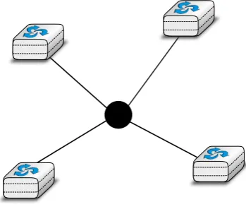
A third organisation of a computer network is a star topology. In such topologies, hosts have a single physical interface and there is one physical link between each host and the center of the star. The node at the center of the star can be either a piece of equipment that amplifies an electrical signal, or an active device, such as a piece
Figure 2.3: A Full mesh network
Figure 2.4: A network organised as a Bus
[image:11.595.209.384.423.571.2]of equipment that understands the format of the messages exchanged through the network. Of course, the failure of the central node implies the failure of the network. However, if one physical link fails (e.g. because the cable has been cut), then only one node is disconnected from the network. In practice, star-shaped networks are easier to operate and maintain than bus-shaped networks. Many network administrators also appreciate the fact that they can control the network from a central point. Administered from a Web interface, or through a console-like connection, the center of the star is a useful point of control (enabling or disabling devices) and an excellent observation point (usage statistics).
Figure 2.5: A network organised as a Star
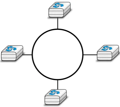
A fourth physical organisation of a network is the Ring topology. Like the bus organisation, each host has a single physical interface connecting it to the ring. Any signal sent by a host on the ring will be received by all hosts attached to the ring. From a redundancy point of view, a single ring is not the best solution, as the signal only travels in one direction on the ring; thus if one of the links composing the ring is cut, the entire network fails. In practice, such rings have been used in local area networks, but are now often replaced by star-shaped networks. In metropolitan networks, rings are often used to interconnect multiple locations. In this case, two parallel links, composed of different cables, are often used for redundancy. With such a dual ring, when one ring fails all the traffic can be quickly switched to the other ring.
A fifth physical organisation of a network is the tree. Such networks are typically used when a large number of customers must be connected in a very cost-effective manner. Cable TV networks are often organised as trees.
Figure 2.6: A network organised as a Ring
Or an ISP network may have a full mesh of devices in the core of its network, and trees to connect remote users.
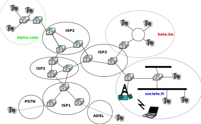
Throughout this book, our objective will be to understand the protocols and mechanisms that are necessary for a network such as the one shown below.
[image:13.595.130.465.132.339.2]S R R R R R R R R R R R R R S R tux@linux# PSTN ISP1 ISP2 ISP2 ISP2 alpha.com beta.be societe.fr ADSL
Figure 2.8: A simple internetwork
The figure above illustrates an internetwork, i.e. a network that interconnects other networks. Each network is illustrated as an ellipse containing a few devices. We will explain throughout the book the different types of devices and their respective roles enabling all hosts to exchange information. As well as this, we will discuss how networks are interconnected, and the rules that guide these interconnections. We will also analyse how the bus, ring and mesh topologies are used to build real networks.
The last point of terminology we need to discuss is the transmission modes. When exchanging information through a network, we often distinguish between three transmission modes. In TV and radio transmission,broadcastis often used to indicate a technology that sends a video or radio signal to all receivers in a given geographical area. Broadcast is sometimes used in computer networks, but only in local area networks where the number of recipients is limited.
The first and most widespread transmission mode is calledunicast. In the unicast transmission mode, information is sent by one sender to one receiver. Most of today???s Internet applications rely on the unicast transmission mode. The example below shows a network with two types of devices : hosts (drawn as computers) and intermediate nodes (drawn as cubes). Hosts exchange information via the intermediate nodes. In the example below, when hostSuses unicast to send information, it sends it via three intermediate nodes. Each of these nodes receives the information from its upstream node or host, then processes and forwards it to its downstream node or host. This is calledstore and forwardand we will see later that this concept is key in computer networks.
A second transmission mode ismulticasttransmission mode. This mode is used when the same information must be sent to a set of recipients. It was first used in LANs but later became supported in wide area networks. When a sender uses multicast to send information toNreceivers, the sender sends a single copy of the information and the network nodes duplicate this information whenever necessary, so that it can reach all recipients belonging to the destination group.
A E
S
D
C B
Figure 2.9: Unicast transmission
A E
S
D
C B
The last transmission mode is the anycasttransmission mode. It was initially defined in RFC 1542. In this transmission mode, a set of receivers is identified. When a source sends information towards this set of receivers, the network ensures that the information is delivered toonereceiver that belongs to this set. Usually, the receiver closest to the source is the one that receives the information sent by this particular source. The anycast transmission mode is useful to ensure redundancy, as when one of the receivers fails, the network will ensure that information will be delivered to another receiver belonging to the same group. However, in practice supporting the anycast transmission mode can be difficult.
A *
S
*
*
B
Figure 2.11: Anycast transmission
In the example above, the three hosts marked with * are part of the same anycast group. When hostS sends information to this anycast group, the network ensures that it will reach one of the members of the anycast group. The dashed lines show a possible delivery via nodes1,2 and4. A subsequent anycast transmission from host S to the same anycast group could reach the host attached to intermediate node3 as shown by the plain line. An anycast transmission reaches a member of the anycast group that is chosen by the network in function of the current network conditions.
2.1 Services and protocols
An important aspect to understand before studying computer networks is the difference between aserviceand a protocol.
In order to understand the difference between the two, it is useful to start with real world examples. The traditional Post provides a service where a postman delivers letters to recipients. The Post defines precisely which types of letters (size, weight, etc) can be delivered by using the Standard Mail service. Furthermore, the format of the envelope is specified (position of the sender and recipient addresses, position of the stamp). Someone who wants to send a letter must either place the letter at a Post Office or inside one of the dedicated mailboxes. The letter will then be collected and delivered to its final recipient. Note that for the regular service the Post usually does not guarantee the delivery of each particular letter, some letters may be lost, and some letters are delivered to the wrong mailbox. If a letter is important, then the sender can use the registered service to ensure that the letter will be delivered to its recipient. Some Post services also provide an acknowledged service or an express mail service that is faster than the regular service.
In computer networks, the notion of service is more formally defined in[X200]. It can be better understood by considering a computer network, whatever its size or complexity, as a black box that provides a service tousers, as shown in the figure below. These users could be human users or processes running on a computer system.
User A User B
Service provider ("the network") Service Access Point
Primitives
Figure 2.12: Users and service provider
Throughout this book, we will define a service as a set of capabilities provided by a system (and its underlying elements) to its user. A user interacts with a service through aservice access point. Note that as shown in the figure above, users interact with one service provider. In practice, the service provider is distributed over several hosts, but these are implementation details that are not important at this stage. These interactions between a user and a service provider are expressed in[X200]by using primitives, as show in the figure below. These primitives are an abstract representation of the interactions between a user and a service provider. In practice, these interactions could be implemented as system calls for example.
User A User B
Service provider ("the network")
X.indication X.response
X.confirm X.request
Figure 2.13: The four types of primitives
Four types of primitives are defined :
??? X.request. This type of primitive corresponds to a request issued by a user to a service provider
??? X.indication. This type of primitive is generated by the network provider and delivered to a user (often related to an earlier and remoteX.requestprimitive)
??? X.response. This type of primitive is generated by a user to answer to an earlierX.indicationprimitive
??? X.confirm. This type of primitive is delivered by the service provide to confirm to a user that a previous X.requestprimitive has been successfully processed.
Primitives can be combined to model different types of services. The simplest service in computer networks is called theconnectionless service3. This service can be modelled by using two primitives :
??? Data.request(source,destination,SDU). This primitive is issued by a user that specifies, as parameters, its (source) address, the address of the recipient of the message and the message itself. We will useService Data Unit(SDU) to name the message that is exchanged transparently between two users of a service.
??? Data.indication(source,destination,SDU). This primitive is delivered by a service provider to a user. It contains as parameters aService Data Unitas well as the addresses of the sender and the destination users.
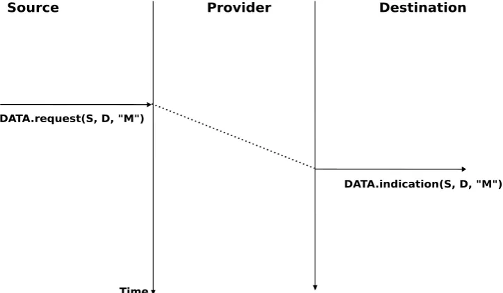
When discussing the service provided in a computer network, it is often useful to be able to describe the inter-actions between the users and the provider graphically. A frequently used representation is thetime-sequence diagram. In this chapter and later throughout the book, we will often use diagrams such as the figure below. A time-sequence diagram describes the interactions between two users and a service provider. By convention, the users are represented in the left and right parts of the diagram while the service provider occupies the middle of the diagram. In such a time-sequence diagram, time flows from the top, to the bottom of the diagram. Each primitive
is represented by a plain horizontal arrow, to which the name of the primitive is attached. The dashed lines are used to represent the possible relationship between two (or more) primitives. Such a diagram provides information about the ordering of the different primitives, but the distance between two primitives does not represent a precise amount of time.
The figure below provides a representation of the connectionless service as atime-sequence diagram. The user on the left, having addressS, issues aData.requestprimitive containing SDUMthat must be delivered by the service provider to destinationD. The dashed line between the two primitives indicates that theData.indicationprimitive that is delivered to the user on the right corresponds to theData.requestprimitive sent by the user on the left.
Source Provider Destination
DATA.request(S, D, "M")
DATA.indication(S, D, "M")
[image:17.595.117.479.185.396.2]Time
Figure 2.14: A simple connectionless service
There are several possible implementations of the connectionless service, which we will discuss later in this book. Before studying these realisations, it is useful to discuss the possible characteristics of the connectionless service. Areliable connectionless serviceis a service where the service provider guarantees that all SDUs submitted in Data.requestsby a user will eventually be delivered to their destination. Such a service would be very useful for users, but guaranteeing perfect delivery is difficult in practice. For this reason, computer networks usually support anunreliable connectionless service.
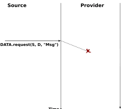
Anunreliable connectionlessservice may suffer from various types of problems compared to areliable connec-tionless service. First of all, anunreliable connectionless servicedoes not guarantee the delivery of all SDUs. This can be expressed graphically by using the time-sequence diagram below.
In practice, anunreliable connectionless servicewill usually deliver a large fraction of the SDUs. However, since the delivery of SDUs is not guaranteed, the user must be able to recover from the loss of any SDU.
A second imperfection that may affect anunreliable connectionless serviceis that it may duplicate SDUs. Some unreliable connectionless service providers may deliver an SDU sent by a user twice or even more. This is illustrated by the time-sequence diagram below.
Finally, some unreliable connectionless service providers may deliver to a destination a different SDU than the one that was supplied in theData.request. This is illustrated in the figure below.
When a user interacts with a service provider, it must precisely know the limitations of the underlying service to be able to overcome any problem that may arise. This requires a precise definition of the characteristics of the underlying service.
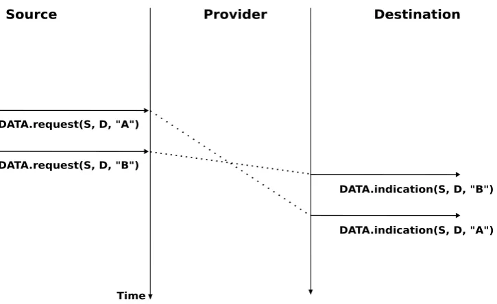
Another important characteristic of the connectionless service is whether it preserves the ordering of the SDUs sent by one user. From the user???s viewpoint, this is often a desirable characteristic. This is illustrated in the figure below.
Source Provider Destination
DATA.request(S, D, "Msg")
[image:18.595.119.371.121.343.2]Time
Figure 2.15: An unreliable connectionless service may loose SDUs
Source Provider Destination
DATA.request(S, D, "Msg")
DATA.indication(S, D, "Msg")
Time
DATA.indication(S, D, "Msg")
[image:18.595.117.480.482.688.2]Source Provider Destination
DATA.request(S, D, "Msg")
DATA.indication(S, D, "XYZ")
[image:19.595.118.478.71.287.2]Time
Figure 2.17: An unreliable connectionless service may deliver erroneous SDUs
Figure 2.18: A connectionless service that preserves the ordering of SDUs sent by a given user
Source Provider Destination
Time DATA.request(S, D, "A")
DATA.indication(S, D, "B") DATA.request(S, D, "B")
DATA.indication(S, D, "A")
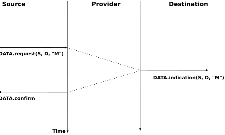
[image:19.595.118.481.525.747.2]Theconnectionless serviceis widely used in computer networks as we will see later in this book. Several variations to this basic service have been proposed. One of these is theconfirmed connectionless service. This service uses aData.confirmprimitive in addition to the classicalData.requestandData.indicationprimitives. This primitive is issued by the service provider to confirm to a user the delivery of a previously sent SDU to its recipient. Note that, like the registered service of the post office, theData.confirmonly indicates that the SDU has been delivered to the destination user. TheData.confirmprimitive does not indicate whether the SDU has been processed by the destination user. Thisconfirmed connectionless serviceis illustrated in the figure below.
Source Provider Destination
Time DATA.request(S, D, "M")
DATA.indication(S, D, "M")
[image:20.595.119.480.166.383.2]DATA.confirm
Figure 2.20: A confirmed connectionless service
The connectionless servicewe have described earlier is frequently used by users who need to exchange small SDUs. Users needing to either send or receive several different and potentially large SDUs, or who need structured exchanges often prefer theconnection-oriented service.
An invocation of theconnection-oriented serviceis divided into three phases. The first phase is the establishment of aconnection. Aconnectionis a temporary association between two users through a service provider. Several connections may exist at the same time between any pair of users. Once established, the connection is used to transfer SDUs. Connectionsusually provide one bidirectional stream supporting the exchange of SDUs between the two users that are associated through theconnection. This stream is used to transfer data during the second phase of the connection called thedata transferphase. The third phase is the termination of the connection. Once the users have finished exchanging SDUs, they request to the service provider to terminate the connection. As we will see later, there are also some cases where the service provider may need to terminate a connection itself.
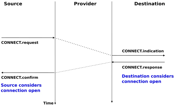
The establishment of a connection can be modelled by using four primitives :Connect.request,Connect.indication, Connect.responseandConnect.confirm. TheConnect.requestprimitive is used to request the establishment of a connection. The main parameter of this primitive is theaddressof the destination user. The service provider delivers aConnect.indicationprimitive to inform the destination user of the connection attempt. If it accepts to establish a connection, it responds with aConnect.responseprimitive. At this point, the connection is considered to be open and the destination user can start sending SDUs over the connection. The service provider processes theConnect.responseand will deliver aConnect.confirmto the user who initiated the connection. The delivery of this primitive terminates the connection establishment phase. At this point, the connection is considered to be open and both users can send SDUs. A successful connection establishment is illustrated below.
Source Provider Destination
Time CONNECT.request
CONNECT.indication
CONNECT.confirm
CONNECT.response
Source considers connection open
Destination considers connection open
Figure 2.21: Connection establishment
cases, the service provider responds to theConnect.requestwith aDisconnect.indicationprimitive whosereason parameter contains additional information about the failure of the connection.
Source Provider Destination
Time CONNECT.request
CONNECT.indication
DISCONNECT.indication
DISCONNECT.request
Connection rejected by provider
Connection rejected by destination
CONNECT.request
[image:21.595.115.479.69.289.2]DISCONNECT.indication
Figure 2.22: Two types of rejection for a connection establishment attempt
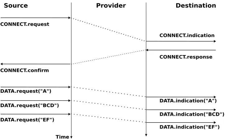
Once the connection has been established, the service provider supplies two data streams to the communicating users. The first data stream can be used by the initiating user to send SDUs. The second data stream allows the responding user to send SDUs to the initiating user. The data streams can be organised in different ways. A first organisation is themessage-modetransfer. With themessage-modetransfer, the service provider guarantees that one and only oneData.indicationwill be delivered to the endpoint of the data stream for eachData.request primitive issued by the other endpoint. Themessage-modetransfer is illustrated in the figure below. The main advantage of themessage-transfermode is that the recipient receives exactly the SDUs that were sent by the other user. If each SDU contains a command, the receiving user can process each command as soon as it receives a SDU.
Source Provider Destination
Time CONNECT.request
CONNECT.indication
CONNECT.confirm
CONNECT.response
DATA.request("A")
DATA.request("BCD")
DATA.request("EF")
DATA.indication("A")
DATA.indication("BCD")
[image:22.595.117.479.68.293.2]DATA.indication("EF")
Figure 2.23: Message-mode transfer in a connection oriented service
of the stream are delivered correctly in the same order at the other endpoint. However, the service provider does not attempt to preserve the boundaries of the SDUs. There is no relation enforced by the service provider between the number ofData.requestand the number ofData.indicationprimitives. Thestream-modeis illustrated in the figure below. In practice, a consequence of the utilisation of thestream-modeis that if the users want to exchange structured SDUs, they will need to provide the mechanisms that allow the receiving user to separate successive SDUs in the byte stream that it receives. As we will see in the next chapter, application layer protocols often use specific delimiters such as the end of line character to delineate SDUs in a bytestream.
Source Provider Destination
Time CONNECT.request
CONNECT.indication
CONNECT.confirm
CONNECT.response
DATA.request("AB")
DATA.request("CD")
DATA.request("EF")
DATA.indication("A")
DATA.indication("B")
DATA.indication("C")
DATA.indication("DEF")
Figure 2.24: Stream-mode transfer in a connection oriented service
[image:22.595.120.474.426.648.2]service provider is forced to terminate a connection it cannot guarantee that all SDUs sent by each user have been delivered to the other user. This connection release is said to be abrupt as it can cause losses of data.
Source Provider Destination
Time DATA.request("A")
DATA.request("B")
DATA.indication("A")
DATA.indication("C")
Connection opened Connection opened
DISCONNECT.indication DISCONNECT.indication
Figure 2.25: Abrupt connection release initiated by the service provider
An abrupt connection release can also be triggered by one of the users. If a user needs, for any reason, to terminate a connection quickly, it can issue aDisconnect.request primitive and to request an abrupt release. The service provider will process the request, stop the two data streams and deliver theDisconnect.indicationprimitive to the remote user as soon as possible. As illustrated in the figure below, this abrupt connection release may cause losses of SDUs.
Source Provider Destination
Time DATA.request("A")
DATA.request("B")
DATA.indication("A")
DATA.request("C")
Connection opened Connection opened
DISCONNECT.req(abrupt)
DISCONNECT.indication
Figure 2.26: Abrupt connection release initiated by a user
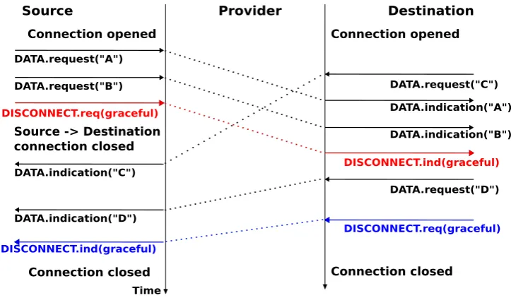
point, all data has been delivered and the two streams have been released successfully and the connection is completely closed.
Source Provider Destination
Time DATA.request("A")
Source -> Destination connection closed
Connection opened Connection opened
DATA.request("B") DATA.request("C")
DATA.indication("A")
DATA.indication("B") DISCONNECT.req(graceful)
DISCONNECT.ind(graceful) DATA.indication("C")
DATA.indication("D")
DATA.request("D")
DISCONNECT.ind(graceful)
DISCONNECT.req(graceful)
[image:24.595.116.478.105.316.2]Connection closed Connection closed
Figure 2.27: Graceful connection release
Note: Reliability of the connection-oriented service
An important point to note about the connection-oriented service is its reliability. Aconnection-orientedservice can only guarantee the correct delivery of all SDUs provided that the connection has been released gracefully. This implies that while the connection is active, there is no guarantee for the actual delivery of the SDUs exchanged as the connection may need to be released abruptly at any time.
2.2 The reference models
Given the growing complexity of computer networks, during the 1970s network researchers proposed various reference models to facilitate the description of network protocols and services. Of these, the Open Systems Interconnection (OSI) model[Zimmermann80]was probably the most influential. It served as the basis for the standardisation work performed within the ISOto develop global computer network standards. The reference model that we use in this book can be considered as a simplified version of the OSI reference model4.
2.2.1 The five layers reference model
Our reference model is divided into five layers, as shown in the figure below.
Starting from the bottom, the first layer is the Physical layer. Two communicating devices are linked through a physical medium. This physical medium is used to transfer an electrical or optical signal between two directly connected devices. Several types of physical mediums are used in practice :
??? electrical cable. Information can be transmitted over different types of electrical cables. The most common ones are the twisted pairs that are used in the telephone network, but also in enterprise networks and coaxial cables. Coaxial cables are still used in cable TV networks, but are no longer used in enterprise networks. Some networking technologies operate over the classical electrical cable.
??? optical fiber. Optical fibers are frequently used in public and enterprise networks when the distance be-tween the communication devices is larger than one kilometer. There are two main types of optical fibers : multimode and monomode. Multimode is much cheaper than monomode fiber because a LED can be
Application
Transport
Network
Datalink
Physical
Physical transmission medium
Figure 2.28: The five layers of the reference model
used to send a signal over a multimode fiber while a monomode fiber must be driven by a laser. Due to the different modes of propagation of light, monomode fibers are limited to distances of a few kilometers while multimode fibers can be used over distances greater than several tens of kilometers. In both cases, repeaters can be used to regenerate the optical signal at one endpoint of a fiber to send it over another fiber.
??? wireless. In this case, a radio signal is used to encode the information exchanged between the communi-cating devices. Many types of modulation techniques are used to send information over a wireless channel and there is lot of innovation in this field with new techniques appearing every year. While most wireless networks rely on radio signals, some use a laser that sends light pulses to a remote detector. These optical techniques allow to create point-to-point links while radio-based techniques, depending on the directionality of the antennas, can be used to build networks containing devices spread over a small geographical area.
An important point to note about the Physical layer is the service that it provides. This service is usually an unreliable connection-oriented service that allows the users of the Physical layer to exchange bits. The unit of information transfer in the Physical layer is the bit. The Physical layer service is unreliable because :
??? the Physical layer may change, e.g. due to electromagnetic interferences, the value of a bit being transmitted
??? the Physical layer may delivermorebits to the receiver than the bits sent by the sender
??? the Physical layer may deliverfewerbits to the receiver than the bits sent by the sender
The last two points may seem strange at first glance. When two devices are attached through a cable, how is it possible for bits to be created or lost on such a cable ?
This is mainly due to the fact that the communicating devices use their own clock to transmit bits at a given bit rate. Consider a sender having a clock that ticks one million times per second and sends one bit every tick. Every microsecond, the sender sends an electrical or optical signal that encodes one bit. The sender???s bit rate is thus 1 Mbps. If the receiver clock ticks exactly5every microsecond, it will also deliver 1 Mbps to its user. However, if the receiver???s clock is slightly faster (resp. slower), than it will deliver slightly more (resp. less) than one million bits every second. This explains why the physical layer may lose or create bits.
Note: Bit rate
In computer networks, the bit rate of the physical layer is always expressed in bits per second. One Mbps is one million bits per second and one Gbps is one billion bits per second. This is in contrast with memory specifica-tions that are usually expressed in bytes (8 bits), KiloBytes ( 1024 bytes) or MegaBytes (1048576 bytes). Thus transferring one MByte through a 1 Mbps link lasts 8.39 seconds.
Bit rate Bits per second
1 Kbps 103
1 Mbps 106
1 Gbps 109
1 Tbps 1012
Physical layer Physical layer
Bits
Physical transmission medium 01010010100010101001010
Figure 2.29: The Physical layer
The physical layer allows thus two or more entities that are directly attached to the same transmission medium to exchange bits. Being able to exchange bits is important as virtually any information can be encoded as a sequence of bits. Electrical engineers are used to processing streams of bits, but computer scientists usually prefer to deal with higher level concepts. A similar issue arises with file storage. Storage devices such as hard-disks also store streams of bits. There are hardware devices that process the bit stream produced by a hard-disk, but computer scientists have designed filesystems to allow applications to easily access such storage devices. These filesystems are typically divided into several layers as well. Hard-disks store sectors of 512 bytes or more. Unix filesystems group sectors in larger blocks that can contain data orinodes representing the structure of the filesystem. Fi-nally, applications manipulate files and directories that are translated in blocks, sectors and eventually bits by the operating system.
Computer networks use a similar approach. Each layer provides a service that is built above the underlying layer and is closer to the needs of the applications.
TheDatalink layerbuilds on the service provided by the underlying physical layer. TheDatalink layerallows two hosts that are directly connected through the physical layer to exchange information. The unit of information exchanged between two entities in theDatalink layer is a frame. A frame is a finite sequence of bits. Some Datalink layers use variable-length frames while others only use fixed-length frames. SomeDatalink layers provide a connection-oriented service while others provide a connectionless service. SomeDatalink layersprovide reliable delivery while others do not guarantee the correct delivery of the information.
An important point to note about theDatalink layeris that although the figure below indicates that two entities of theDatalink layerexchange frames directly, in reality this is slightly different. When theDatalink layerentity on the left needs to transmit a frame, it issues as manyData.requestprimitives to the underlyingphysical layer as there are bits in the frame. The physical layer will then convert the sequence of bits in an electromagnetic or optical signal that will be sent over the physical medium. Thephysical layeron the right hand side of the figure will decode the received signal, recover the bits and issue the correspondingData.indicationprimitives to itsDatalink layerentity. If there are no transmission errors, this entity will receive the frame sent earlier.
Datalink Physical
Frames Datalink
Physical
Figure 2.30: The Datalink layer
contains information about its origin and its destination, and usually passes through several intermediate devices called routers on its way from its origin to its destination.
Physical layer Datalink Network Physical layer Datalink Network Physical layer Datalink Network Packets Packets
Figure 2.31: The network layer
Most realisations of the network layer, including the internet, do not provide a reliable service. However, many applications need to exchange information reliably and so using the network layer service directly would be very difficult for them. Ensuring the reliable delivery of the data produced by applications is the task of the transport layer. Transport layer entities exchangesegments. A segment is a finite sequence of bytes that are transported inside one or more packets. A transport layer entity issues segments (or sometimes part of segments) asData.requestto the underlying network layer entity.
There are different types of transport layers. The most widely used transport layers on the Internet are TCP
,that provides a reliable connection-oriented bytestream transport service, andUDP,that provides an unreliable connection-less transport service.
Physical layer Datalink Network Physical layer Datalink Network Transport Physical layer Datalink Network Transport Segments
Figure 2.32: The transport layer
The upper layer of our architecture is theApplication layer. This layer includes all the mechanisms and data structures that are necessary for the applications. We will use Application Data Unit (ADU) to indicate the data exchanged between two entities of the Application layer.
Physical layer Datalink Network Physical layer Datalink Network Transport Physical layer Datalink Network Transport ADU Application Application
Figure 2.33: The Application layer
2.2.2 The TCP/IP reference model
In contrast with OSI, the TCP/IP community did not spend a lot of effort defining a detailed reference model; in fact, the goals of the Internet architecture were only documented after TCP/IP had been deployed[Clark88].RFC 1122, which defines the requirements for Internet hosts, mentions four different layers. Starting from the top, these are :
??? an Application layer
??? a Transport layer
??? an Internet layer which is equivalent to the network layer of our reference model
??? a Link layer which combines the functionalities of the physical and datalink layers of our five-layer reference model
2.2.3 The OSI reference model
Compared to the five layers reference model explained above, theOSI reference model defined in [X200] is divided in seven layers. The four lower layers are similar to the four lower layers described above. The OSI reference model refined the application layer by dividing it in three layers :
??? the Session layer. The Session layer contains the protocols and mechanisms that are necessary to organize and to synchronize the dialogue and to manage the data exchange of presentation layer entities. While one of the main functions of the transport layer is to cope with the unreliability of the network layer, the session???s layer objective is to hide the possible failures of transport-level connections to the upper layer higher. For this, the Session Layer provides services that allow to establish a session-connection, to support orderly data exchange (including mechanisms that allow to recover from the abrupt release of an underlying transport connection), and to release the connection in an orderly manner.
??? the Presentation layer was designed to cope with the different ways of representing information on comput-ers. There are many differences in the way computer store information. Some computers store integers as 32 bits field, others use 64 bits field and the same problem arises with floating point number. For textual information, this is even more complex with the many different character codes that have been used6. The
situation is even more complex when considering the exchange of structured information such as database records. To solve this problem, the Presentation layer contains provides for a common representation of the data transferred. TheASN.1notation was designed for the Presentation layer and is still used today by some protocols.
??? the Application layer that contains the mechanisms that do not fit in neither the Presentation nor the Session layer. The OSI Application layer was itself further divided in several generic service elements.
Note: Where are the missing layers in TCP/IP reference model ?
The TCP/IP reference places the Presentation and the Session layers implicitly in the Application layer. The main motivations for simplifying the upper layers in the TCP/IP reference model were pragmatic. Most Internet applications started as prototypes that evolved and were later standardised. Many of these applications assumed that they would be used to exchange information written in American English and for which the 7 bits US-ASCII character code was sufficient. This was the case for email, but as we???ll see in the next chapter, email was able to evolve to support different character encodings. Some applications considered the different data representations explicitly. For example,ftpcontained mechanisms to convert a file from one format to another and the HTML language was defined to represent web pages. On the other hand, many ISO specifications were developed by committees composed of people who did not all participate in actual implementations. ISO spent a lot of effort analysing the requirements and defining a solution that meets all of these requirements. Unfortunately, some of the specifications were so complex that it was difficult to implement them completely and the standardisation bodies defined recommended profiles that contained the implemented sets of options...
Figure 2.34: The seven layers of the OSI reference model
2.3 Organisation of the book
This document is organised according to theTCP/IPreference model and follows a top-down approach. Most of the classical networking textbooks chose a bottom-up approach, i.e. they first explained all the electrical and optical details of the physical layer then moved to the datalink layer. This approach worked well during the infancy of computer networks and until the late 1990s. At that time, most students were not users of computer networks and it was useful to explain computer networks by building the corresponding protocols from the simplest, in the physical layer, up to the application layer. Today, all students are active users of Internet applications, and starting to learn computer networking by looking at bits is not very motivating. Starting from [KuroseRoss09], many textbooks and teachers have chosen a top-down approach. This approach starts from applications such as email and web that students already know and explores the different layers, starting from the application layer. This approach works quite well with today???s students. The traditional bottom-up approach could in fact be considered as an engineering approach as it starts from the simple network that allows the exchange of bits, and explains how to combine different protocols and mechanisms to build the most complex applications. The top-down approach could on the other hand be considered as a scientific approach. Like biologists, it starts from an existing (man-built) system and explores it layer by layer.
Besides the top-down versus bottom-up organisation, computer networking books can either aim at having an in-depth coverage of a small number of topics, or at having a limited coverage of a wide range of topics. Covering a wide range of topics is interesting for introductory courses or for students who do not need a detailed knowledge of computer networks. It allows the students to learn alittle about everything and then start from this basic knowledge later if they need to understand computer networking in more detail. This books chose to cover, in detail, a smaller number of topics than other textbooks. This is motivated by the fact that computer networks often need to be pushed to their limits. Understanding the details of the main networking protocols is important to be able to fully grasp how a network behaves or extend it to provide innovative services7.
The book is organised as follows: We first describe the application layer in chapterThe application Layer. Given the large number of Internet-based applications, it is of course impossible to cover them all in detail. Instead we focus on three types of Internet-based applications. We first study the Domain Name System (DNS) and then explain some of the protocols involved in the exchange of electronic mail. The discussion of the application layer ends with a description of the key protocols of the world wide web.
All these applications rely on the transport layer that is explained in chapterThe transport layer. This is a key layer in today???s networks as it contains all the mechanisms necessary to provide a reliable delivery of data over an unreliable network. We cover the transport layer by first developing a simple reliable transport layer protocol and then explain the details of the TCP and UDP protocols used in TCP/IP networks.
After the transport layer, we analyse the network layer in chapterThe network layer. This is also a very important layer as it is responsible for the delivery of packets from any source to any destination through intermediate routers. In the network layer, we describe the two possible organisations of the network layer and the routing protocols based on link-state and distance vectors. Then we explain in detail the IPv4, IPv6, RIP, OSPF and BGP protocols that are actually used in today???s Internet.
The last chapter of the book is devoted to the datalink layer. In chapterThe datalink layer and the Local Area Networks, we begin by explaining the principles of the datalink layers on point-to-point links. Then, we focus on the Local Area Networks. We first describe the Medium Access Control algorithms that allow multiple hosts to share one transmission medium. We consider both opportunistic and deterministic techniques. We then explain in detail two types of LANs that are important from a deployment viewpoint today : Ethernet and WiFi.
The application Layer
The Application Layer is the most important and most visible layer in computer networks. Applications reside in this layer and human users interact via those applications through the network.
In this chapter, we first briefly describe the main principles of the application layer and focus on the two most important application models : the client-server and the peer-to-peer models. Then, we review in detail two families of protocols that have proved to be very useful in the Internet : electronic mail and the protocols that allow access to information on the world wide web. We also describe the Domain Name System that allows humans to use user-friendly names while the hosts use 32 bits or 128 bits long IP addresses.
3.1 Principles
The are two important models used to organise a networked application. The first and oldest model is the client-server model. In this model, a client-server provides services to clients that exchange information with it. This model is highly asymmetrical : clients send requests and servers perform actions and return responses. It is illustrated in the figure below.
Figure 3.1: The client-server model
The client-server model was the first model to be used to develop networked applications. This model comes naturally from the mainframes and minicomputers that were the only networked computers used until the 1980s. Aminicomputeris a multi-user system that is used by tens or more users at the same time. Each user interacts with the minicomputer by using a terminal. Those terminals, were mainly a screen, a keyboard and a cable directly connected to the minicomputer.
Networked applications do not exchange random messages. In order to ensure that the server is able to understand the queries sent by a client, and also that the client is able to understand the responses sent by the server, they must both agree on a set of syntactical and semantic rules. These rules define the format of the messages exchanged as well as their ordering. This set of rules is called an application-levelprotocol.
Anapplication-level protocolis similar to a structured conversation between humans. Assume that Alice wants to know the current time but does not have a watch. If Bob passes close by, the following conversation could take place :
??? Alice :Hello
??? Bob :Hello
??? Alice :What time is it ?
??? Bob :11:55
??? Alice :Thank you
??? Bob :You???re welcome
Such a conversation succeeds if both Alice and Bob speak the same language. If Alice meets Tchang who only speaks Chinese, she won???t be able to ask him the current time. A conversation between humans can be more complex. For example, assume that Bob is a security guard whose duty is to only allow trusted secret agents to enter a meeting room. If all agents know a secret password, the conversation between Bob and Trudy could be as follows :
??? Bob :What is the secret password ?
??? Trudy :1234
??? Bob :This is the correct password, you???re welcome
If Alice wants to enter the meeting room but does not know the password, her conversation could be as follows :
??? Bob :What is the secret password ?
??? Alice :3.1415
??? Bob :This is not the correct password.
Human conversations can be very formal, e.g. when soldiers communicate with their hierarchy, or informal such as when friends discuss. Computers that communicate are more akin to soldiers and require well-defined rules to ensure an successful exchange of information. There are two types of rules that define how information can be exchanged between computers :
??? syntactical rules that precisely define the format of the messages that are exchanged. As computers only process bits, the syntactical rules specify how information is encoded as bit strings
??? organisation of the information flow. For many applications, the flow of information must be structured and there are precedence relationships between the different types of information. In the time example above, Alice must greet Bob before asking for the current time. Alice would not ask for the current time first and greet Bob afterwards. Such precedence relationships exist in networked applications as well. For example, a server must receive a username and a valid password before accepting more complex commands from its clients.
Let us first discuss the syntactical rules. We will later explain how the information flow can be organised by analysing real networked applications.
Application-layer protocols exchange two types of messages. Some protocols such as those used to support electronic mail exchange messages expressed as strings or lines of characters. As the transport layer allows hosts to exchange bytes, they need to agree on a common representation of the characters. The first and simplest method to encode characters is to use theASCIItable. RFC 20provides the ASCII table that is used by many protocols on the Internet. For example, the table defines the following binary representations :
??? A:1000011b
??? 0:0110000b
??? @:1000000b
??? space:0100000b
In addition, theASCIItable also defines several non-printable or control characters. These characters were de-signed to allow an application to control a printer or a terminal. These control characters includeCRandLF, that are used to terminate a line, and theBellcharacter which causes the terminal to emit a sound.
??? carriage return(CR) :0001101b
??? line feed(LF) :0001010b
??? Bell:0000111b
TheASCIIcharacters are encoded as a seven bits field, but transmitted as an eight-bits byte whose high order bit is usually set to0. Bytes are always transmitted starting from the high order or most significant bit.
Most applications exchange strings that are composed of fixed or variable numbers of characters. A common solution to define the character strings that are acceptable is to define them as a grammar using a Backus-Naur Form (BNF) such as the Augmented BNF defined inRFC 5234. A BNF is a set of production rules that generate all valid character strings. For example, consider a networked application that uses two commands, where the user can supply a username and a password. The BNF for this application could be defined as shown in the figure below.
Figure 3.2: A simple BNF specification
The example above defines several terminals and two commands : usercommand andpasswordcommand. The ALPHAterminal contains all letters in upper and lower case. In theALPHA rule,%x41corresponds to ASCII character code 41 in hexadecimal, i.e. capitalA. TheCRandLFterminals correspond to the carriage return and linefeed control characters. TheCRLFrule concatenates these two terminals to match the standard end of line termination. TheDIGITterminal contains all digits. TheSPterminal corresponds to the white space characters. The usercommand is composed of two strings separated by white space. In the ABNF rules that define the messages used by Internet applications, the commands are case-insensitive. The rule???user???corresponds to all possible cases of the letters that compose the word between brackets, e.g.user,uSeR,USER,usER, ... Ausername contains at least one letter and up to 8 letters. User names are case-sensitive as they are not defined as a string between brackets. Thepasswordrule indicates that a password starts with a letter and can contain any number of letters or digits. The white space and the control characters cannot appear in apassworddefined by the above rule.
Besides character strings, some applications also need to exchange 16 bits and 32 bits fields such as integers. A naive solution would have been to send the 16- or 32-bits field as it is encoded in the host???s memory. Unfortunately, there are different methods to store 16- or 32-bits fields in memory. Some CPUs store the most significant byte of a 16-bits field in the first address of the field while others store the least significant byte at this location. When networked applications running on different CPUs exchange 16 bits fields, there are two possibilities to transfer them over the transport service :
??? send the most significant byte followed by the least significant byte
??? send the least significant byte followed by the most significant byte
libraries1used to write networked applications contain functions to convert multi-byte fields from memory to the network byte order and vice versa.
Besides 16 and 32 bit words, some applications need to exchange data structures containing bit fields of various lengths. For example, a message may be composed of a 16 bits field followed by eight, one bit flags, a 24 bits field and two 8 bits bytes. Internet protocol specifications will define such a message by using a representation such as the one below. In this representation, each line corresponds to 32 bits and the vertical lines are used to delineate fields. The numbers above the lines indicate the bit positions in the 32-bits word, with the high order bit at position0.
Figure 3.3: Message format
The message mentioned above will be transmitted starting from the upper 32-bits word in network byte order. The first field is encoded in 16 bits. It is followed by eight one bit flags (A-H), a 24 bits field whose high order byte is shown in the first line and the two low order bytes appear in the second line followed by two one byte fields. This ASCII representation is frequently used when defining binary protocols. We will use it for all the binary protocols that are discussed in this book.
We will discuss several examples of application-level protocols in this chapter.
3.1.1 The peer-to-peer model
The peer-to-peer model emerged during the last ten years as another possible architecture for networked appli-cations. In the traditional client-server model, hosts act either as servers or as clients and a server serves a large number of clients. In the peer-to-peer model, all hosts act as both servers and clients and they play both roles. The peer-to-peer model has been used to develop various networked applications, ranging from Internet telephony to file sharing or Internet-wide filesystems. A detailed description of peer-to-peer applications may be found in [BYL2008]. Surveys of peer-to-peer protocols and applications may be found in[AS2004]and[LCP2005].
3.1.2 The transport services
Networked applications are built on top of the transport service. As explained in the previous chapter, there are two main types of transport services :
??? theconnectionlessordatagramservice
??? theconnection-orientedorbyte-streamservice
The connectionless service allows applications to easily exchange messages or Service Data Units. On the Internet, this service is provided by the UDP protocol that will be explained in the next chapter. The connectionless transport service on the Internet is unreliable, but is able to detect transmission errors. This implies that an application will not receive an SDU that has been corrupted due to transmission errors.
The connectionless transport service allows networked application to exchange messages. Several networked applications may be running at the same time on a single host. Each of these applications must be able to exchange SDUs with remote applications. To enable these exchanges of SDUs, each networked application running on a host is identified by the following information :
??? thehoston which the application is running
??? theport numberon which the applicationlistensfor SDUs
On the Internet, theport numberis an integer and thehostis identified by its network address. As we will see in chapterThe network layerthere are two types of Internet Addresses :
??? IP version 4addresses that are 32 bits wide
??? IP version 6addresses that are 128 bits wide
[image:35.595.116.480.498.715.2]IPv4 addresses are usually represented by using a dotted decimal representation where each decimal number corresponds to one byte of the address, e.g. 203.0.113.56. IPv6 addresses are usually represented as a set of hexadecimal numbers separated by semicolons, e.g. 2001:db8:3080:2:217:f2ff:fed6:65c0. Today, most Internet hosts have one IPv4 address. A small fraction of them also have an IPv6 address. In the future, we can expect that more and more hosts will have IPv6 addresses and that some of them will not have an IPv4 address anymore. A host that only has an IPv4 address cannot communicate with a host having only an IPv6 address. The figure below illustrates two that are using the datagram service provided by UDP on hosts that are using IPv4 addresses.
Figure 3.4: The connectionless or datagram service
The second transport service is the connection-oriented service. On the Internet, this service is often called the byte-stream serviceas it creates a reliable byte stream between the two applications that are linked by a transport connection. Like the datagram service, the networked applications that use the byte-stream service are identified by the host on which they run and a port number. These hosts can be identified by an IPv4 address, an IPv6 address or a name. The figure below illustrates two applications that are using the byte-stream service provided by the TCP protocol on IPv6 hosts. The byte stream service provided by TCP is reliable and bidirectional.
3.2 Application-level protocols
Many protocols have been defined for networked applications. In this section, we describe some of the important applications that are used on the Internet. We first explain the Domain Name System (DNS) that enables hosts to be identified by human-friendly names instead of the IPv4 or IPv6 addresses that are used by the network. Then, we describe the operation of electronic mail, one of the first killer applications on the global Internet, and the protocols used on world wide web.
3.2.1 The Domain Name System
In the early days of the Internet, there were only a few number of hosts (mainly minicomputers) connected to the network. The most popular applications were remote login and file transfer. By 1983, there were already five hundred hosts attached to the Internet. Each of these hosts were identified by a unique IPv4 address. Forcing human users to remember the IPv4 addresses of the remote hosts that they want to use was not user-friendly. Human users prefer to remember names, and use them when needed. Using names as aliases for addresses is a common technique in Computer Science. It simplifies the development of applications and allows the developer to ignore the low level details. For example, by using a programming language instead of writing machine code, a developer can write software without knowing whether the variables that it uses are stored in memory or inside registers.
Because names are at a higher level than addresses, they allow (both in the example of programming above, and on the Internet) to treat addresses as mere technical identifiers, which can change at will. Only the names are stable. On today???s Internet, where switching to another ISP means changing your IP addresses, the user-friendliness of domain names is less important (they are not often typed by users) but their stability remains a very important, may be their most important property.
The first solution that allowed applications to use names was thehosts.txtfile. This file is similar to the symbol table found in compiled code. It contains the mapping between the name of each Internet host and its associated IP address2. It was maintained by SRI International that coordinated the Network Information Center (NIC). When
a new host was connected to the network, the system administrator had to register its name and IP address at the NIC. The NIC updated thehosts.txtfile on its server. All Internet hosts regularly retrieved the updatedhosts.txt
file from the server maintained bySRI. This file was stored at a well-known location on each Internet host (see
RFC 952) and networked applications could use it to find the IP address corresponding to a name.
Ahosts.txtfile can be used when there are up to a few hundred hosts on the network. However, it is clearly not suitable for a network containing thousands or millions of hosts. A key issue in a large network is to define a suitable naming scheme. The ARPANet initially used a flat naming space, i.e. each host was assigned a unique name. To limit collisions between names, these names usually contained the name of the institution and a suffix to identify the host inside the institution (a kind of poor man???s hierarchical naming scheme). On the ARPANet few institutions had several hosts connected to the network.
However, the limitations of a flat naming scheme became clear before the end of the ARPANet andRFC 819
proposed a hierarchical naming scheme. WhileRFC 819discussed the possibility of organising the names as a directed graph, the Internet opted eventually for a tree structure capable of containing all names. In this tree, the top-level domains are those that are directly attached to the root. The first top-level domain was.arpa3. This
top-level name was initially added as a suffix to the names of the hosts attached to the ARPANet and listed in thehosts.txt file. In 1984, the.gov,.edu,.com, .miland.orggeneric top-level domain names were added and
RFC 1032proposed the utilisation of the two letterISO-3166country codes as top-level domain names. Since
ISO-3166defines a two letter code for each country recognised by the United Nations, this allowed all countries to automatically have a top-level domain. These domains include.befor Belgium,.frfor France,.usfor the USA, .iefor Ireland or.tvfor Tuvalu, a group of small islands in the Pacific and.tmfor Turkmenistan. Today, the set of top-level domain-names is managed by the Internet Corporation for Assigned Names and Numbers (ICANN). Recently,ICANNadded a dozen of generic top-level domains that are not related to a country and the.cattop-level domain has been registered for the Catalan language. There are ongoing discussions withinICANN to increase the number of top-level domains.
2 The hosts.txt file is not maintained anymore. A historical snapshot retrieved on April 15th, 1984 is available from http://ftp.univie.ac.at/netinfo/netinfo/hosts.txt
Each top-level domain is managed by an organisation that decides how sub-domain names can be registered. Most top-level domain names use a first-come first served system, and allow anyone to register domain names, but there are some exceptions. For example,.govis reserved for the US government,.intis reserved for international organisations and names in the.caare mainlyreservedfor companies or users who are present in Canada.
Figure 3.6: The tree of domain names
RFC 1035recommended the followingBNFfor fully qualified domain names, to allow host names with a syntax which works with all applications (the domain names themselves have a much richer syntax).
Figure 3.7: BNF of the fully qualified host names
This grammar specifies that a host name is an ordered list of labels separated by the dot (.) character. Each label can contain letters, numbers and the hyphen character (-)4. Fully qualified domain names are read from left to right. The first label is a hostname or a domain name followed by the hierarchy of domains and ending with the root implicitly at the right. The top-level domain name must be one of the registered TLDs5. For example, in the above figure,www.whitehouse.govcorresponds to a host namedwwwinside thewhitehousedomain that belongs to thegovtop-level domain. info.ucl.ac.becorresponds to theinfodomain inside theucldomain that is included in theacsub-domain of thebetop-level domain.
This hierarchical naming scheme is a key component of the Domain Name System (DNS). The DNS is a dis-tributed database that contains mappings between fully qualified domain names and IP addresses. The DNS uses the client-server model. The clients are hosts that need to retrieve the mapping for a given name. Eachnameserver
stores part of the distributed database and answers the queries sent by clients. There is at least onenameserverthat is responsible for each domain. In the figure below, domains are represented by circles and there are three hosts inside domaindom(h1,h2andh3) and three hosts inside domaina