Smith, C. C. (2012).Ge´otechnique 62, No. 7, 563–571 [http://dx.doi.org/10.1680/geot.10.P.136]
563
Limit loads for a shallow anchor/trapdoor embedded in a non-associative
Coulomb soil
C . C . S M I T H
A theoretical methodology for determining the range of possible plane-strain limit loads acting on an anchor or trapdoor buried within a non-associative Coulomb soil is presented. Solutions are given for shallow anchors and trapdoors underlying both weightless soil with surface load and soil possessing self-weight with no surface load. A method for determining limit loads for combined scenarios is additionally outlined. Solutions are shown to correlate favourably with experimental and finite-element data in the literature.
KEYWORDS: anchors; limit state design/analysis; plasticity
Cette communication pre´sente une me´thodologie the´ori-que pour la de´termination de la plage de charges limites de de´formation plane agissant sur un dispositif d’ancrage ou une trappe enterre´s dans un sol de Coulomb non associatif. Des solutions sont propose´es pour des disposi-tifs d’ancrage ou des trappes a` faible profondeur place´s sous un sol de´pourvu de poids avec charge surfacique, et un sol posse´dant son propre poids sans charge surfaci-que. En outre, on pre´sente e´galement une me´thode de de´termination des charges limites pour des sce´narios mixtes. Les solutions pre´sentent une bonne corre´lation avec des donne´es expe´rimentales et aux e´le´ments finis contenues dans des documents techniques sur ce sujet.
INTRODUCTION
An associative geotechnical limit analysis requires that the angle of dilation ł of a soil be taken equal to the angle of shearing resistance. This assumption underpins the power-ful upper- and lower-bound theorems of plasticity, and the existence of a unique limit load. However, it is known that real soils are non-associative with dilation angleł,. If a soil is modelled as a non-associative plastic material, then it is found that: (a) the limit load is not unique, and may be dependent on initial conditions and stress path to failure; (b) the limit load will always be less than or equal to the associative limit load (Chen, 1975).
Non-associativity can potentially reduce the limit load through two main processes: (a) a direct change to the collapse kinematics; (b) softening in shear bands (due purely to non-associativity), as discussed for example by Vermeer (1990).
These observations apply to materials that are rigid and perfectly plastic, with a non-associated flow rule, and which do not require the additional consideration of (true) strain-softening (e.g. transition from peak to critical state strength), which is beyond the scope of this paper.
Static determinacy
Although there exist a large number of associative solu-tions in the literature to a wide range of geotechnical problems, very few closed-form solutions exist for non-associative limit loads. Drescher & Detournay (1993), for example, considered the kinematic analysis of statically determinate non-associative problems on the assumption that full (non-associative) strain-softening was able to manifest itself along slip planes. Without strain-softening, the collapse load for a statically determinate mechanism may otherwise be unaffected by non-associativity.
This paper, in contrast, examines the class of statically
indeterminate problems, and specifically the anchor/trapdoor problem. In these cases, static indeterminacy provides one vehicle by which the non-associative and associative solu-tions can differ. This indeterminacy manifests itself in the anchor/trapdoor problem, in that the horizontal stresses are not constrained to a single value at collapse. Such problems are attractive for the derivation of a closed-form solution, in that they retain a useful degree of simplicity.
The primary aim of this paper is to illustrate how the range of possible non-associative limit loads might be bracketed in the context of closed-form solutions to the anchor/trapdoor problem.
DERIVATION OF A NON-ASSOCIATIVE SOLUTION The procedure outlined by Davis (1968) is adopted. An admissible plastic stress distribution is first generated, to which a corresponding pattern of velocity characteristics is mapped according to the appropriate flow rule. A distribu-tion of velocities corresponding to this pattern of velocity characteristics and satisfying the deformation boundary con-ditions is then derived. For the solution to be considered admissible (although not necessarily unique), the stress distribution must extend over the whole soil mass in a statically admissible manner without exceeding the strength. Additionally, as pointed out by Drescher & Detournay (1993), it is necessary to confirm that the combined stress and velocity fields are thermodynamically admissible.
In a previous paper, Smith (1998) presented a rigorous, almost identical set of upper- and lower-bound solutions applicable to the anchor/trapdoor problem in an associative Coulomb material. These solutions will be used as the basis of the derivation of non-associative limit loads. Simple solutions involving only one velocity discontinuity at each edge of the trapdoor will be adopted.
The condition of co-axiality is adopted in this paper. In this case, the principal axes of strain increment and stress are assumed to be coincident. Solutions are derived for both weightless soil with surface load and soil possessing self-weight with no surface load. The former case lends itself more readily to straightforward analysis, and will be used to explore the solution space in detail, whereas the latter case, Manuscript received 5 December 2010; revised manuscript accepted
22 September 2011. Published online ahead of print 19 May 2012. Discussion on this paper closes on 1 December 2012, for further details see p. ii.
Geotechnical Engineering Group, Department of Civil and
which is of more general practical relevance, will be exam-ined in a single context.
A comparison is then made with finite-element and ex-perimental data in the literature to contextualise the derived solutions. Finally, examination of translational failure me-chanism analysis for the trapdoor problem is undertaken, which leads to a method for determining limit loads for combined surface load and self-weight scenarios.
PROBLEM DEFINITION
It is required to find compatible equilibrium stress and velocity fields consistent with the stress and displacement boundary conditions relevant to a rigid anchor/trapdoor of width B underlying a uniform body of cohesionless soil of angle of shearing resistance , unit weight ª and depth D, as depicted in Fig. 1. The surface of the soil above the anchor/trapdoor carries a uniform vertical surcharge load q>0.
The solutions presented in this paper will be restricted to the plane-strain case of a horizontal anchor/trapdoor. Follow-ing the conventions applied in a previous paper (Smith, 1998), the term ‘trapdoor’ will be used to indicate both an anchor (passive) and a trapdoor (active). Strictly, the solu-tions are directly applicable only to a trapdoor in a basement layer. The behaviour of an anchor plate will differ, in that a rising anchor plate leaves a void beneath itself, allowing localised flow around the anchor. This may affect the limit load, and will usually affect large-displacement loading, but is beyond the scope of this paper.
Solutions will be derived in terms of stress state described by mean stress and major principal stress direction measured anticlockwise from the negative x-axis. In this framework the magnitude of the major principal stress is given by(1þsin):
WEIGHTLESS SOIL WITH A SURFACE LOAD Solution characteristics
Where the soil is assumed to have zero self-weight (ª¼0) and uniformly distributed properties of angle of shearing resistance () and angle of dilation (ł), then the limit load F per unit length for the anchor or trapdoor may be expressed in a dimensionless form as
F
qB¼12 D
Bð,łÞ (1)
where the sign depends on whether displacement is active () or passive (+).
The same general arguments as given by Smith (1998) for a soil possessing self-weight may be applied to this scenario, and are briefly summarised here. The attributes of a stress field compatible with an underlying displacing trapdoor within a rigid basement layer are as follows.
(a) The orientation of the principal stresses within the soil just beneath the soil surface can only be vertical or horizontal, and will generally differ for soil lying directly above the trapdoor (e.g. in the region of R in Fig. 1) and for soil lying some distance to the side (e.g. in the region of P). A transition zone (in the region of O) must therefore exist between the two.
(b) The direction of shear stresses along, for example, a line joining O and E in Fig. 1 must act as to oppose the soil motion (this ensures thermodynamic admissibility). (c) Any velocity characteristics in the problem must pass
through a zone in which the stress field is limiting. For the purposes of the initial analysis, a shallow trapdoor will be considered, and is defined as one buried at a sufficiently small embedment ratio (D/B) such that the soil stress fields generated at each edge (E and E9) of the trapdoor do not interact. A complete analysis therefore requires the investigation of the stress field at one edge only, as shown in Fig. 2, and will be applicable to both active and passive trapdoors, depending on whether point E is taken as the left- or right-hand edge of the trapdoor.
The simplest plausible stress and velocity field for this problem compatible with the required attributes above is one that is scale independent or geometrically self-similar with vertical or horizontal major principal stresses at the surface and varying only with angle about O, and with a single velocity discontinuity OE separating two rigid blocks, where E is the edge of the trapdoor. This stress field also requires the assumption of a partially rough basement layer with interface frictiontypically less than .
Although an infinite number of continuous stress fields exist that satisfy such conditions, a much simpler, but still broadly representative, subset of solutions can be examined through the use of a small number of stress discontinuities.
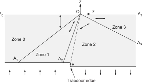
As depicted in Fig. 2, an arrangement of three disconti-nuities OA1, OA2 and OA3 can be shown to give the
required form of equilibrium stress field. (E may lie either side of A2.) This produces a considerably simpler solution
than for the self-weight problem, as there are only four distinct stress states in zones 0, 1, 2 and 3, where zone i represents the area AiOAiþ1: Let discontinuity Ai be
orien-tated at angle Łi anticlockwise from OA0, and the mean
stress and major principal stress direction (measured antic-lockwise from OA0) in each zone i be denoted i and i
respectively. From the problem definition,0is thus equal to
908and3¼08. Limiting conditions are required only in the
zone (j) in which the velocity characteristic (OE in Fig. 2) is manifested: thus each zone imay be assigned a mobilised angle of shearing resistance mi <, with the condition that m
j ¼: Derivation of the equations that may be used to
E⬘ E
B
Passive mode
Active mode R O
P
S
Trapdoor
q
D Soil unit
[image:2.595.320.550.607.739.2]weightγ
Fig. 1. The trapdoor problem: active and passive modes
A4
A3
x
A2
A1
O
E
Trapdoor edge
A0
y
Zone 0
Zone 1
Zone 2
[image:2.595.61.293.642.760.2]Zone 3
relate the stress states in adjacent zones is given in Appen-dix 1.
Normally it would be expected that the velocity disconti-nuities would emerge at an angle 45ł/2 to the surface. However, for the proposed solution, this does not occur, owing to the velocity discontinuity emerging at a singularity.
Solutions with limiting stresses in all zones
In the first instance the case where m1,2,3,4¼ will be considered. In general, solutions may be derived using the iterative approach described in Appendix 1. However, it is insightful to consider the range of distinct equilibrium stress fields that may be determined for all values of Ł1 from 0 to
45 +/2. Values of Ł1, Ł2,Ł3, 1,2 are plotted against Ł1
in Fig. 3 for the case¼308.
The above stress field solution may be used to determine the corresponding velocity characteristics that are orientated at v to the principal stress directions, where v¼
=4ł=2 for the coaxial flow rule.
For kinematic compatibility the line OE must be orien-tated at ł to the vertical away from the upward-displacing basement layer (or towards the downward-displacing base-ment layer), where ł is the angle of dilation. For this to occur the following relationship must exist betweenłand in the yielding zone, as shown in Fig. 6.
þv¼ŁE (2)
whereŁE(angle A0OE) is given by
ŁE¼=2ł (3)
Hence
ł¼=22 (4)
and
ŁE¼2 (5)
However, there is only a narrow range of stress fields for which equation (4) is satisfied with 0,ł,. If OE lies in zone A1OA2, thenŁE must be less thanŁ2, and if OE lies in
zone A2OA3, then ŁE must be greater thanŁ2:Values of ŁE,
determined from equation (5), for each zone are also plotted in Fig. 3, where ŁE1 represents ŁE derived for zone 1
(A1OA2), andŁE2 representsŁE derived for zone 2 (A2OA3).
For zone 1, valid points are below point A in Fig. 3 (ŁE1,Ł2). These are impossible, as they imply ł..
However, in zone 2, valid values ofŁE2 exist between points
B and C in Fig. 3, giving a range of 0,ł,14.488. For simple velocity fields of this nature, there exists a
valuełmax for each angle such that viable solutions occur
only for 0,ł,łmax: For ł.łmax the simple velocity
field solution is not possible. However, from a practical point of view, this is not a problem, as łmax typically exceeds that
expected for real soils.
Velocity and stress characteristics are shown in Fig. 4 for an example problem with ¼308, ł¼48 and Ł1¼418.
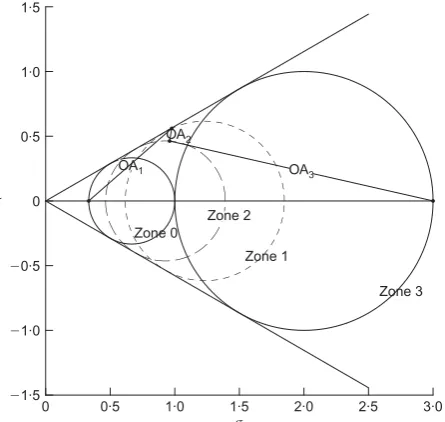
The corresponding Mohr’s circles are given in Fig. 5. If the stress state (mean stress , major principal stress direction ) along OE is known, then the load on a finite-width trapdoor or anchor may be determined from equation (1), where
¼cotŁEþ
sinŁE
sincos 2ð ŁEÞ cosŁE
½ (6)
Values of against are plotted for viable values of ł in 58 increments in Fig. 7. Also plotted in this graph are the associative case upper and lower bounds U and L:
The upper bound is given by tan , as demonstrated later. The lower bound is found by the same method as described by Smith (1998) for soil possessing self-weight; all possible sets of Ł1, Ł2, Ł3 are searched, and the value of ŁE that
gives the largest value of determined. It is found that ŁE¼Ł2 always. It is seen that the lower and upper bounds
are almost identical, thus defining the true associative load to within 4%.
θ1
θ2
ξ1
ξ2
θE1
θE2
60 50 40
30 20
0 0 30 60 90 120 150 180
Discontinuity angles and principal stress
directions: deg
rees
10
θ1: degrees
A
B C
[image:3.595.306.531.347.464.2]θ3
Fig. 3. Variation of discontinuity angles and major principal stress directions withŁ1 for 308for a trapdoor underlying a weightless soil with surface load
A4
A3
O
A2 E
A1
A0
[image:3.595.309.532.527.738.2]εvε v
Fig. 4. Velocity characteristics (thin lines) for weightless soil with surface load ( 308, ł 48, Ł1 418). Bold lines indicate the pattern of stress characteristics
3·0
0 0·5 1·0 1·5 2·0 2·5
σ
⫺1·5 ⫺1·0 ⫺0·5 0 0·5 1·0 1·5
τ
OA3
OA1
Zone 3 Zone 2
Zone 1 Zone 0
OA2
Fig. 5. Mohr’s circles for the stress states in each zone for a weightless soil problem with surface loadqB 1 ( 308,ł 48, Ł1 418)
[image:3.595.46.276.588.740.2]Solutions with yield only in deforming zone
So far, only solutions with yield in all zones have been considered. As stated earlier, yield is required only in the zone(s) where deformation takes place. Thus m may be
lower than in all other zones. In these cases, it is found that the largest (smallest) anchor (trapdoor) capacity occurs with the assumption of m¼ in all zones, and the lowest
values occur for low values of m3: In all analyses carried
out, it was found that was unaffected by the value of m 0
orm1 (except where an invalid solution was produced), and that the velocity discontinuity always lay in zone 2. Selected results are presented in Table 1.
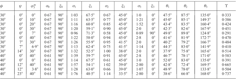
It is seen that values of ranging from 0.333 to 0.451 are possible for ¼308andł¼0 (compare with 0.577 for the associative case). The lowest value occurs for m
3 ¼0:
This indicates that it may be possible to find a solution where the sense of the Mohr’s circle in zone 3 is reversed, that is, where 3¼908. Solutions may in fact be found, and
are listed in the second part of Table 1. In these cases it is possible to reach lower values of , down to 0.291 for ¼308andł¼0, which is almost half that of the associa-tive value.
Higher values are also possible if values of m
3 . are
considered, as shown in the second part of Table 1. This may be a possibility where is considered a critical state value whilem
3 is considered a peak value.
Solutions for non-zero values of ł and for ¼408 are given in the third and fourth parts of Table 1.
A wider range may exist if other solution types other than that considered in this paper exist.
Scope of validity of solutions
The solutions so derived may be considered to be valid for all depths (although not necessarily critical). For exam-ple, for an active trapdoor, A3 intersects the line of
symme-try, as depicted in Fig. 8. However, a further discontinuity line may be employed downwards from A3 to the
intersec-tion with OE such that the major principal stress direcintersec-tion in the zone between it and the symmetry line remains horizon-tal. It is possible to show that this sequence of intersecting discontinuity zones can be continued downwards, but this is beyond the scope of this paper. Similar arguments may be made for the passive trapdoor case.
O
A4
ξ
A0
E
ψ ψ
[image:4.595.65.289.48.155.2]εv θE
Fig. 6: Relationship between, v, andł andŁE on right-hand edge of sliding-wedge boundary
1·8
1·6
1·4
1·2
1·0
0·8
0·6
0·4
0·2
0 ⌼
10 20 30 40 50 60
φ: degrees
Lower bound Upper bound
ψ⫽5°
ψ⫽0°
ψ⫽10°
ψ⫽15°
ψ⫽20°
ψ⫽25°
ψ⫽30°
ψ⫽35°
[image:4.595.64.293.205.361.2]ψ⫽40°
Fig. 7. Variation of associative upper and lower bounds and non-associative values of with for a trapdoor underlying a weightless soil with surface load
Table 1. Example sets of equilibrium discontinuities for weightless soil showing range of possiblevalues for non-associative shearing
ł jm
3 0 0 1 1 2 2 3 3 Ł1 Ł2 Ł3
308 08 08 0.67 908 1.03 67.58 0.67 45.08 1.0 08 47.58 87.58 135.08 0.333
308 08 108 0.67 908 1.11 63.58 0.77 45.08 1.21 08 45.08 85.18 149.38 0.386
308 08 208 0.67 908 1.16 60.88 0.85 45.08 1.52 08 43.48 83.58 160.48 0.424
308 08 308 0.67 908 1.20 59.18 0.90 45.08 2.0 08 42.38 82.68 167.98 0.451
308 08 78 0.67 908 0.96 71.38 0.58 45.08 0.89 908 49.88 89.88 124.88 0.291
308 08 408 0.67 908 1.22 58.08 0.94 45.08 2.8 08 41.68 81.98 172.78 0.470
308 78 308 0.67 908 1.26 55.98 0.95 41.58 2.0 08 40.28 79.28 166.78 0.484
308 78 6.98 0.67 908 1.13 62.48 0.75 41.58 1.14 08 44.38 83.08 141.98 0.410
308 148 308 0.67 908 1.32 52.58 1.00 38.08 2.0 08 37.98 75.88 165.68 0.514
408 08 408 0.61 908 1.39 59.78 0.91 45.08 2.8 08 46.78 78.18 171.08 0.583
408 08 08 0.61 908 1.14 67.58 0.61 45.08 1.0 08 52.08 83.08 135.08 0.391
408 128 408 0.61 908 1.57 54.18 1.02 39.08 2.80 08 42.88 72.48 169.58 0.665
408 128 3.88 0.61 908 1.28 63.08 0.66 39.08 1.07 08 48.98 78.08 133.88 0.504
408 238 408 0.61 908 1.76 48.58 1.14 33.58 2.80 08 38.68 66.88 168.08 0.737
A2
A1
A3
O
E
A0
D
B/2
[image:4.595.321.547.391.539.2] [image:4.595.57.554.611.779.2]SOIL POSSESSING SELF-WEIGHT WITH NO SURFACE LOAD
The method of generating limiting stress fields for such problems has been described in detail by Smith (1998), who used the approach to generate lower-bound solutions to the associative flow case. Where the soil is assumed to have uniformly distributed properties of angle of friction (), angle of dilation (ł) and self-weightª, then the limit loadF per unit length for the anchor or trapdoor may be expressed in a dimensionless form as
F ªDB¼1
D
BØð,łÞ (7)
where the sign depends on whether displacement is active () or passive (+).
While a similar pattern of three stress discontinuities is required to generate valid solutions, the stress characteristics in zones A1OA2 and A2OA3 are curved, owing to the soil
self-weight. However, velocity characteristics may still be generated from the stress fields, as outlined for the weight-less soil, and simple velocity fields with a single velocity discontinuity can be found, as depicted in Fig. 9. From these
solutions, values of Ø and łmax may be found for each
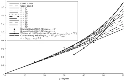
value of. In this paper solutions are presented only for the assumption of limiting conditions in all zones. Values of Ø are given in Fig. 10, together with values of the associative upper and lower bounds ØU and ØL: The methodology for
determining solution validity limits on the embedment ratio D/B for the case of soil possessing self-weight has been outlined by Smith (1998).
INTERPRETATION OF THE LIMIT LOAD
Unlike associative solutions, non-associative solutions are not necessarily unique, and a number of solutions may exist, depending on initial conditions and the stress path to failure. The work here attempts to bracket the range of possible solutions. For example, for the solution type depicted in Fig. 4 it is not necessary that the soil in zones 1, 2, 3 and 4 be in a state of limiting equilibrium, as the only plastic deformation is taking place in zone 2. If non-limiting states are considered in these zones, then values ofandØlower than for the full limiting case are obtained (as would be expected), and łmax also reduces.
It is suggested that higher non-associative limit loads are unlikely to be found. The solutions presented are likely to be an upper bound to the set of non-associative solutions.
Comparison with finite-element and experimental data Rowe & Davis (1982) undertook elasto-plastic FE analysis of the anchor uplift problem, and presented data for both ł¼0 and ł¼ cases. These are plotted in Fig. 10 (averaged from data for D/B ¼1, 2 and 3) and show excellent agreement, providing support for the current the-ory. Examination of the velocity fields presented by Rowe & Davis (1982) for shallow anchors also shows similar behav-iour to that predicted by the current theory.
White et al. (2008) provided an extensive survey of the experimental data available in the literature for model anchor and pipe tests, together with a proposed limit equilibrium
O
A0
A1 A2
A3
A4
[image:5.595.50.277.307.436.2]E
Fig. 9. Velocity characteristics for soil possessing self-weight with no surface load ( 308,ł 108). Trapdoor edge located at E
1·8
1·6
1·4
1·2
1·0
0·8
0·6
0·4
0·2
0
Ψ
10 20 30 40 50 60
φ: degrees
Lower bound Upper bound
ψ⫽5°
ψ⫽0°
ψ⫽10°
ψ⫽15°
ψ⫽20°
ψ⫽25°
ψ⫽30°
ψ⫽35°
ψ⫽40°
0
ψ⫽45°
Rowe & Davis (1982) FE dataψ⫽0°
Rowe & Davis (1982) FE dataψ⫽φ
Whiteet al. (2008) adjusted LE model,ψmeasured(φcrit⫽32°)
Current theory assuming 32°, ,
( ) 0·8
φ φ φ
ψ φ φ
crit peak
peak crit
⫽ ⫽
⫽ ⫺
Fig. 10. Variation of associative upper and lower bounds and non-associative values ofØwithfor a trapdoor underlying a soil possessing self-weight with no surface load
[image:5.595.88.496.484.748.2]model for predicting anchor and pipe uplift capacity that requires values ofcrit,peak andł (see Appendix 2). They
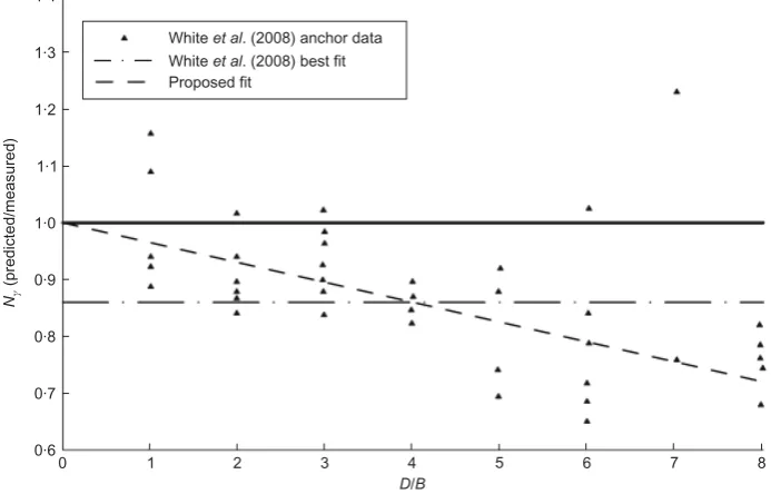
demonstrated that their model underpredicts the anchor data on average by 14%, as shown in Fig. 11, in which their anchor data are reproduced (where Nª¼F/ªDB). This un-derprediction is averaged over all burial depth/width ratios, and unfortunately (a) does not directly include dilation data, and (b) is also in terms of Nª¼1 +Ø(D/B) rather than Ø, which is where the uncertainty lies. However, an approx-imate comparison can be made. Examination of Fig. 11, where Nª is plotted against burial depth ratio, indicates broad increase of error with burial depth ratio to the order of 28% (approximately double the average, as expected) at D/B¼8, that is, at a gradient of 0.28/8¼0.035. Thus
Nª,measured
Nª,predicted
10:035D=B¼
1þðD=BÞØW
10:035ðD=BÞ (8)
where ØW is the predicted value of Ø from White et al.
(2008); see Appendix 2. Hence Nª,measured 1þ
D BØW
1þ0:035D B
1þ ØW 1þ0:035
D B
þ0:035
D B
(9)
To avoid the (D/B)2 term, the middle term on the right-hand side will be approximately taken atD/B¼4. Hence
Ømeasured1:14ØWþ0:035 (10)
The values of Ømeasured assuming crit¼328, ¼peak
and ł¼(peakcrit)=0:8, as proposed in White et al.
(2008), are plotted in Fig. 10 for values of ¼35–558, together with values predicted by the current theory for the same parameters. It is seen that the modified White et al. (2008) values are reasonable fits to the current data at the higher values of . The lower values are still within the expected range of the current theory, based on the trends observed for the weightless soil problem. Of course, the current model pertains to shallow anchors only, and the comparison is seen through the filter of the White et al. (2008) limit equilibrium solution. Also, other effects such as
geometrical change prior to failure have not been accounted for.
Broadly, the FE and experimental data seem to support the assumption that yield is occurring in all zones. On this basis, based on Fig. 10, non-associativity leads to an approx-imate 12% reduction in the value of Ø, compared with the associative value for practical cases.
COMBINED ANALYSIS FOR SOIL POSSESSING SELF-WEIGHT AND SUBJECTED TO SURFACE LOAD Translational failure mechanism analysis of combined problem
A simple translational mechanism appropriate to the trap-door/anchor problem has been outlined by Murray & Geddes (1987). This employs two velocity discontinuities emerging upwards from each trapdoor edge, as illustrated for the passive case in Fig. 12.
The analysis presented here extends previous analyses by considering both self-weight and surface loading. From the corresponding force polygon relating U, Vand W it can be shown that
V ¼WcosðÆÞ
sinðÆþÞ (11)
1·4
1·3
1·2
1·1
1·0
0·8
0·7
1 2 5 6 7 8
D B/ 0·9
0·6
0 3 4
Nγ
(predicted/measured)
Whiteet al. (2008) anchor data
Whiteet al. (2008) best fit
[image:6.595.322.549.289.472.2]Proposed fit
Fig. 11. Anchor data reproduced from Whiteet al. (2008) Fig. 5(d), illustrating the best fit proposed by Whiteet al.(2008) and alternative fit proposed in the current work
S G
α β
F
D γ
q B/2
E
R
[image:6.595.131.478.527.749.2]U V W
whereWis given by the self-weight and surface loading on triangle EFG
W¼ qDþ1
2ªD
2
tanÆþtan
ð Þ (12)
The actual force per unit length, Fp, on the (passive) half
trapdoor ES is given by Fp
B ¼q 1 2D
B tan
þªD 1D
Btan
þ2V
B sinðþÞ (13) Fp
B ¼q 1þ 2D
B Yp
ªD 1þD BYp
(14)
where
Yp¼ tanþ
sinðþÞcosðÆÞðtanÆþtanÞ
sinðÆþÞ
(15) the subscript p denoting the passive case. In general, for both active (a) and passive (p) cases, it can be shown that
1 B
Fp
Fa
¼q 12D B Y
þªD 1D
BY
(16)
and Yp
Ya
¼ tanðÞ þsinðÞcosðÆÞðtanÆþtanÞ
sinðÆþÞ
(17) For an upper bound associative analysis, Y must be minimised, subject to the kinematic constraints Æ> for the passive case or > for the active case. This occurs when either of the velocity discontinuities is orientated at angle to the vertical away from the part of the basement layer that is undergoing upward relative movement. In either case equation (17) reduces to
U¼ØU¼Ymin¼tan (18)
At this stage, kinematically, the other discontinuity vanishes for the associative case. The solution is valid for all depth ratios D/B for the passive case, and for D=B,1=(2 tan) for the active case. For the active case for D=B.1=(2 tan) a kinematically admissible solution is one involving a single displacing isosceles triangle of soil whose base is defined by the trapdoor and whose apex angle equals 2. No deforma-tion reaches the surface, and yield parameters Ua¼0 and
ØUa¼B[1B=(4Dtan)]=D:
For the non-associative case, values of Ymay be larger or smaller than as given in equation (18), as the kinematic constraints are less restrictive on Æ and , and no obvious distinct solution presents itself.
General limit loads for soil possessing self-weight and subjected to surface load
In common with the classic Terzaghi bearing capacity equation for footings, it is proposed that the load for an anchor/trapdoor underlying a soil possessing self-weightwith surface self-weight may be approximated by equation (19) as
p¼qNqþªDNª (19)
where
Nq¼1
2D
B (20)
Nª¼1D
BØ (21)
where the + sign corresponds to the passive case and the
sign to the active case.
For an associative soil, the upper bounds combine exactly as indicated in equation (19) (as derived in equation (16)). Applying the principles of superposition to the lower-bound case, as detailed by Bolton & Lau (1993) for the bearing capacity problem, it is easily shown that superposition of the lower-bound limiting stress fields will always lead to a equilibrium stress field that nowhere violates yield (but is not necessarily everywhere in yield). Thus the combined lower-bound solutions will also be a lower bound. As the individual lower bounds are almost identical to their respec-tive upper bounds, then the combined lower bound will be almost identical to the combined upper bound. Thus equa-tion (19) is closely applicable to the associative case.
For the non-associative case, the above arguments are not applicable, but it is not unreasonable to propose that the above equation will give a good approximation to the com-bined load, particularly for large values of dilatancy.
CONCLUSIONS
(a) A class of complete equilibrium limiting stress fields and compatible velocity fields for the statically indeterminate shallow anchor/trapdoor problem in non-associative cohesionless soils has been presented. The analysis utilises the coaxial flow rule, and can be used to predict the range of limit loads on both active and passive trapdoors (anchors). For ¼308, ł¼0, for example, possible limit loads down to approximately 50% of the associative limit load could be found for the problem scenario with surface surcharge and weightless soil. (b) Very good agreement is demonstrated with FE data in the
literature, and generally good agreement with experi-mental data, which is indicative that an analysis assuming general yield in the vicinity of an anchor edge is appropriate. For anchors overlain by typical real soils this would imply that the component of normalised non-associative limit load (F/ªDB) that varies with depth/ width ratio (D/B) is approximately 12% lower than the corresponding associative limit load.
(c) The solutions presented in this paper illustrate the general principle that statically indeterminate problems can have non-associative limit loads that differ from the associative limit loads, owing to the indeterminacy.
(d) The analysis covers both cases of weightless soil with surface loading and cases of soil possessing self-weight with no surface loading and presents an equation that may be used to predict the combined case. This combined equation is shown to provide solutions for the associative case to within a few per cent of the true values.
NOTATION
B breadth of anchor or trapdoor D depth of anchor or trapdoor
F force per unit length on anchor or trapdoor Nq,Nª dimensionless load factors
p average limit vertical stress on anchor or trapdoor q soil surface surcharge stress
r,Ł polar coordinates
Y dimensionless load function for translational mechanism analysis
ª unit weight of soil
roughness of anchor or trapdoor
angle of stress characteristics to major principal stress direction
v angle of velocity characteristics to major principal stress
direction
orientation of principal stress direction to horizontal
mean stress
n, normal and shear stresses
dimensionless load function for weightless soil problem
angle of shearing resistance
m mobilised angle of shearing resistance crit critical state angle of shearing resistance peak peak angle of shearing resistance
Ø dimensionless load function for soil possessing self-weight problem
ł dilatancy angle
APPENDIX 1: ANALYSIS OF TRAPDOOR UNDERLYING WEIGHTLESS SOIL WITH A SURFACE LOAD AND VARIABLE MOBILISED STRENGTHS
Consider the change in stress state passing from zone ito zone i+ 1.
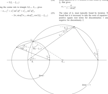
Let discontinuity between zoneiand zone i+ 1 be orientated at angleŁiþ1. LetSidenote the centre of the Mohr’s circle (with stress magnitude i) representing the state of stress in zone i and Iiþ1
represent the intersection of the two Mohr’s circles representing the state of stress in zonesiandi+ 1. As indicated in Fig. 13, it can be shown that
Siþ1SS^iIiþ1¼þ2ðŁiþ1iÞ (22)
Si^SSiþ1Iiþ1¼2ðiþ1Łiþ1Þ (23)
Siþ1^IIiþ1Si¼½þ2ðŁiþ1iÞ 2ðiþ1Łiþ1Þ
¼2ðiiþ1Þ
(24)
Applying the cosine rule to triangleSiIiþ1 Siþ1 gives
iiþ1
ð Þ2¼2
isin
2m
i þ
2
iþ1sin 2m
iþ1
2isinmiiþ1sinmiþ1cos 2ðiiþ1Þ
(25)
or
2
iþ
2
iþ12iiþ1¼2isin
2m
i þ
2
iþ1sin 2m
iþ1
2isinmiiþ1sinmiþ1cos 2ðiiþ1Þ
(26)
If i is known, then iþ1 can be found from the solution of the
quadratic equation
2
iþ1 1sin 2m
iþ1
iþ1f2i 12 sinmi sinmiþ1
3cos 2ðiiþ1Þ
þ2
i 1sin
2m
i
¼0
(27)
There are two roots to this quadratic equation, leading to two valid solutions. Solutions may be derived as follows.
0¼
q 1þsinm
0
(28)
0¼=2 (29)
3¼0 (30)
Assuming the velocity discontinuity is in zone 2,
2þvþł¼=2 (31)
v¼=4ł=2 (32)
2¼=4ł=2 (33)
and
m
2 ¼ (34)
If 1 is known, then the values of 1,2 and 3 can be computed
using equation (27). A solution is thus found by finding the value of
1 that gives
3¼
q 1sinm
3
(35)
The value of 1 must typically found by iteration. Typically it is
found that it is necessary to take the roots of equation (27) with the positive square root terms for discontinuities 1 and 3 and the negative for discontinuity 2.
Si⫹1 Si
2(ξi⫺ξi⫹1) π
ξ
/2⫺
i
ξ θ
i i
⫹ ⫹
1 1 ⫺
Zonei⫹1
Zonei
ξi
ξi⫹1
ξi⫹1
θi⫹1
[image:8.595.79.509.379.752.2]θi⫹1 Ii⫹1
APPENDIX 2: WHITE ET AL.(2008) LIMIT EQUILIBRIUM ANALYSIS
The core limit equilibrium equations presented by White et al. (2008) are reproduced below (in current notation).
F
ªDB¼1þ
D
BØ peak,crit,ł
(36)
ؼtanłþ tanpeaktanł
1þK0
2
1K0
ð Þcos 2ł
2
(37)
K0¼1sincrit (38)
REFERENCES
Bolton, M. & Lau, C. (1993). Vertical bearing capacity factors for circular and strip footings on Mohr–Coulomb soil. Can. Geo-tech. J.30, No. 6, 1024–1033.
Chen, W. F. (1975).Limit analysis and soil plasticity. Developments in Geotechnical Engineering 7. Amsterdam: Elsevier.
Davis, E. (1968). Theories of plasticity and the failure of soil masses. In Soil mechanics: Selected topics (ed. I. K. Lee), pp. 341–380. London: Butterworth.
Drescher, A. & Detournay, E. (1993). Limit load in translational failure mechanisms for associative and non-associative materials. Ge´otechnique 43, No. 3, 443–456, http://dx.doi.org/10.1680/ geot.1993.43.3.443.
Murray, E. & Geddes, J. (1987). Uplift of anchor plates in sand.J. Geotech. Engng Div. ASCE113, No. 3, 202–215.
Rowe, R. & Davis, E. (1982). The behaviour of anchor plates in sand. Ge´otechnique32, No. 1, 25–41, http://dx.doi.org/10.1680/ geot.1982.32.1.25.
Smith, C. (1998). Limit loads for an anchor/trapdoor embedded in an associative Coulomb soil. Int. J. Numer. Anal. Meth. Geo-mech.22, No. 11, 855–865.
Vermeer, P. (1990). The orientation of shear bands in biaxial tests. Ge´otechnique 40, No. 2, 223–236, http://dx.doi.org/10.1680/ geot.1990.40.2.223.
White, D., Cheuk, C. & Bolton, M. (2008). The uplift resistance of pipes and plate anchors buried in sand. Ge´otechnique 58, No. 10, 771–779, http://dx.doi.org/10.1680/geot.2008.3692.