Int. J. Electrochem. Sci., 10 (2015) 579 - 588
International Journal of
ELECTROCHEMICAL
SCIENCE
www.electrochemsci.org
Development of a Multiple Biosensor and its Application of
Biofuel Cell
Cheng-Yu Yang1, Tsung-Hsuan Tsai1, Shen-Ming Chen*1, Bih-Show Lou2*, Xiaoheng Liu3 1
Electroanalysis and Bioelectrochemistry Lab, Department of Chemical Engineering and
Biotechnology, National Taipei University of Technology, No.1, Section 3, Chung-Hsiao East Road, Taipei 106, Taiwan (ROC).
2
Chemistry Division, Center for General Education, Chang Gung University, Tao-Yuan, Taiwan. 3
Key Laboratory of Education Ministry for Soft Chemistry and Functional Materials, Nanjing University of Science and Technology, Nanjing 210094, China
*E-mail: [email protected] ; [email protected]
Received: 4 August 2014 / Accepted: 18 November 2014 / Published: 2 December 2015
The gold nanoparticles (GNP) and functionalized carbon nanotube (f-CNT) film (GNP-f-CNT) was prepared on glassy carbon electrode (GCE) by multiple scan cyclic voltammetry. The glucose oxidase (GOx) was physical adsorbed on the GNP-f-CNT film surface. The electrochemical measurements and surface morphology of the as-prepared films were studied using field emission scanning electron microscopy (FE-SEM) and X-ray diffraction (XRD). The proposed film were demonstrated for the determination of dissolved oxygen using linear sweep voltammetry (LSV) and rotating disk electrode voltammetry (RDE). The proposed electrodes for the construction of biofuel cell (BFC) was achieved up to 22.6W cm-2
, and worked well as a biosensor for both glucose and dissolved oxygen with high sensitivity of 281.86 A mM−1
cm−2 and 205.73 A L mg−1 cm−2, respectively. The proposed protocol for synthesizing the GOx/GNP-f-CNT bionanocomposite is simple, convenient and fast in operation, which is expected to find wide biosensing and bioelectronic applications.
Keywords: Gold nanoparticles, multi-walled carbon nanotube, glucose, electrocatalysis, dissolved oxygen, biofuel cell
1. INTRODUCTION
reactions, thereby replacing traditional electrocatalysts present in conventional fuel cells. These systems generate electricity under mild conditions through the oxidation of renewable energy sources without greenhouse gas emissions or environmental pollution. The advantage of biofuel cells lies in the aspects of enzymatic catalysis namely, activity at near-room temperature, neutral pH and selectivity [5]. The vast majority of biofuel cells are based on the electroenzymatic oxidation of glucose and oxygen reduction [6]. However, enzymatic biocatalytic assemblies on electrode surfaces usually do not achieve significant electron transfer between the enzyme and the conductive support, mostly because of the electrical insulation of the biocatalytic site by the surrounding protein shells [3,7]. In general, redox mediators are introduced to shuttle electrons between the enzyme active site and the electrode surface [8]. The performance of glucose biofuel cells is largely governed by the electrodes materials used and the mechanism of their assembly on the electrode surface [9-11]. Recently we reported an easy and fast production process of enzyme electrodes based on mechanical compression of a mixture of carbon nanotubes (CNT), enzymes and mediators [12]. In contrast to conventional enzyme electrodes which are based on the functionalization of a conductive surface, this procedure consists to create a bioelectrode directly from CNT and proteins. The advantage of this process lies in the absence of chemical binding of enzymes and mediators to the electrode where is the main BFC configurations involve enzymes and redox mediators chemically grafted on the electrode surface [13].
The application of nanoparticles as biocathode has been found as interesting topic [14-16]. Various types of modified electrodes have been reported for the electrochemical reduction of oxygen to determine the oxygen dissolution, including the preanodized screen-printed carbon electrode modified by palladium nanoparticles [17,18] or platinum nanoparticles [19]. In addition, gold nanoparticles electrodeposited on carbon substrates [20] and CNTs [21] had been performed as well. Our group also reported the silver/ionic liquid composite [22] and dye/nanocomposite nanoparticles with conducting polymers [23,24] as novel electrocatalysts for the electrocatalytic reduction of dissolved oxygen.
The aim of this study was to design basic, enzyme-free at biocathode side biofuel cell. Therefore, our work focused on the fabrication of bioanode and biocathode using GOx/GNP-f-CNT and GNP-f-CNT nanocomposite film. The biofuel cell performances of the devices were analyzed.
2. EXPERIMENTAL
2.1. Reagents
used to prepare all the solutions. A 0.05 M phosphate buffer solution (PBS) of pH 7.0 was prepared using Na2HPO4 (0.05 M) and NaH2PO4 (0.05 M).
2.2. Apparatus
All electrochemical experiments were performed using CHI 410a potentiostats (CH Instruments, USA). The BAS GCE (=0.3 cm in diameter, exposed geometric surface area 0.07 cm2
, Bioanalytical Systems, Inc., USA) was used. A conventional three-electrode system was used which consists of an Ag/AgCl (saturated KCl) as a reference, proposed film modified GCE as working and platinum wire as counter electrode. Field emission scanning electron microscope (FE-SEM) images were recorded using a HITACHI S-4700 (Japan). The dissolved oxygen was measured using a commercial dissolved oxygen meter 323-A (Wissenschaftlich-Technische Werkstatten 2BA202, Germany). The biofuel cell performance was analyzed by KEITHLEY 2400 source meter. The buffer solution was entirely altered by deaerating using nitrogen gas atmosphere. The oxygen gas was purged as required and the concentrations were measured
3. RESULTS AND DISCUSSION
[image:3.596.106.485.414.706.2]3.1. FE-SEM and XRD Analysis of Various Film
The surface morphology of GOx/GNP-f-CNT has been examined using FE-SEM analysis. Here the studies could furnish the comprehensive information about the surface morphology of GNP-f-CNT film coated on the GCE surface. As shown in Fig. 1, the surface morphology of (A) f-CNT, (B) GNP-f-CNT and (C) GOx/GNP-f-GNP-f-CNT films were examined by FE-SEM. As shown in Fig. 1(A), the f-CNT film show a network structure which is distributed over the GCE during the drop casting process. The f-CNT film provided a substrate for successful electrodeposition of gold nanoparticles on the GCE surface (Fig. 1(B)). The average particle size of f-CNT and gold nanoparticles falls in the range of 80– 150 nm and 10–25 nm. For formation process of GNP-f-CNT, the functionalization of MWCNT would be slightly affected by gold-sulfur of proposed film composite in the presence of gold nanoparticles. Also, the GOx can be easily dropped and stably adsorbed on the GNP-f-CNT surface (Fig. 1(C)). Finally, SEM results clearly explicate the morphological nature in the surface of the GOx/GNP-f-CNT nanocomposite film.
XRD has been employed to validate the proposed GNP-f-CNT structure on the ITO glass substrate. Fig. 1(D) shows the XRD patterns obtained for the GNP-f-CNT nanoparticles. There are important characteristic peaks obtained for the electrodeposited GNP-f-CNT film. For gold patterns, the peaks were found in 38.07°, 44.26°, 64.38° and 77.31° for Au(111), Au(200), Au(220) and Au(311), respectively. For f-CNT patterns, the peaks were found at around 26.34°. All these XRD peaks clearly validate the presence of GNP-f-CNT on the ITO surface.
3.2. Electrochemical Oxidation to glucose on GOx/GNT-f-CNT Film
[image:4.596.212.380.431.662.2]
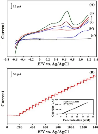
Fig. 2(A) shows LSVs of GOx/GNT-f-CNT/GCE in 0.05 M PBS pH 7.0 containing different concentrations of glucose from 0 to 5 mM in curves (a) to (d), respectively. The oxidation peak current increases with increasing concentration of glucose in the solution. The peak current in the oxidation overpotential of 0.6 V for glucose increases remarkably and indicates the effective electrocatalytic function of GOx/GNT-f-CNT/GCE towards the oxidation of glucose. The electrochemical behavior of glucose at GNT-f-CNT/GCE has been investigated and shown in curve b’. The oxidation peak potential of glucose results in a positive shift (1.0 V) and its peak current is decreased from 50.6 to 14.7 μA. By the same way, the bare GCE (curve a’) has no obviously oxidation peak. The above result indicates that the GOx is stably modified on the GNT-f-CNT/GCE and shows obviously electrocatalytic oxidation of glucose.
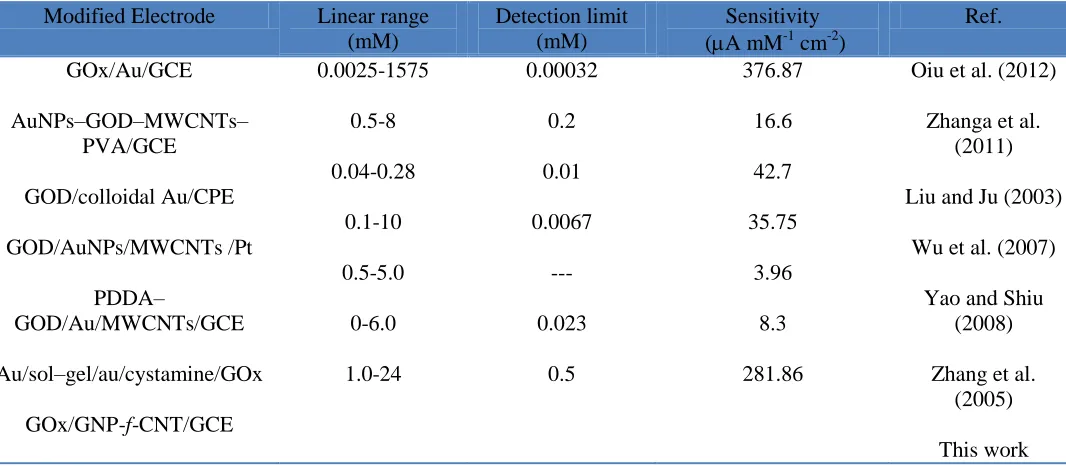
[image:5.596.34.567.441.674.2]Well-defined, stable, and fast amperometric responses were observed at an applied potential of 0.6 V with successive step additions of glucose in the stirred PBS (pH=7.0). As the glucose was injected, the steady-state currents reached another steady-state value (95% of the maximum) in less than 3 s. The calibration curve of the GOx/GNT-f-CNT/GCE is shown in the inset of Fig. 2(B). An expanded linear response the range of 1.0×10⁻³ to 2.4×10⁻² M with a correlation coefficient of 0.999 was obtained with a detection limit of 5.0×10⁻⁴ M (S/N=3). Compared with other enzymatic or non-enzymatic hydrogen peroxide biosensor containing gold nanoparticles [27-32] depicted in Table 1, the GOx/GNT-f-CNT/GCE exhibits the high sensitivity with good linear range and fast amperometric response towards glucose.
Table 1. Comparison of sensing abilities for glucose with different modified electrodes.
Modified Electrode Linear range
(mM)
Detection limit (mM)
Sensitivity (A mM-1 cm-2)
Ref. GOx/Au/GCE AuNPs–GOD–MWCNTs– PVA/GCE GOD/colloidal Au/CPE GOD/AuNPs/MWCNTs /Pt PDDA– GOD/Au/MWCNTs/GCE Au/sol–gel/au/cystamine/GOx
GOx/GNP-f-CNT/GCE
0.0025-1575 0.5-8 0.04-0.28 0.1-10 0.5-5.0 0-6.0 1.0-24 0.00032 0.2 0.01 0.0067 --- 0.023 0.5 376.87 16.6 42.7 35.75 3.96 8.3 281.86
Oiu et al. (2012)
Zhanga et al. (2011)
Liu and Ju (2003)
Wu et al. (2007)
Yao and Shiu (2008)
Zhang et al. (2005)
This work
3.3. Electrochemical Reduction to Dissolved Oxygen on GNT-f-CNT Film
[image:6.596.144.454.234.668.2]
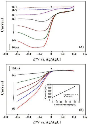
reduction of dissolved oxygen (0–30 mg/L) on GNP-f-CNT/GCE in 0.05 M pH 7 PBS. The LSVs exhibited an anodic peak at about -0.2 V in the absence of dissolved oxygen. Upon the oxygen gas purged in the PBS, a new reduction peak of dissolved oxygen appeared at about -0.17 V. An increase in the concentration of dissolved oxygen simultaneously produced an increase in the reduction current. This behavior is typical of that expected for the mediated reduction. Similarly, the lower reduction current with the higher overpotential for the determination of dissolved oxygen is revealed in curves (a’), (b’) and (c’) for using bare GCE, f-CNT/GCE and GNP/GCE, respectively. The above results demonstrated that GNT-f-CNT film accelerates the electron transfer rates of dissolved oxygen, which was due to the presence of f-CNT particles [33,34].
[image:7.596.37.565.346.548.2]
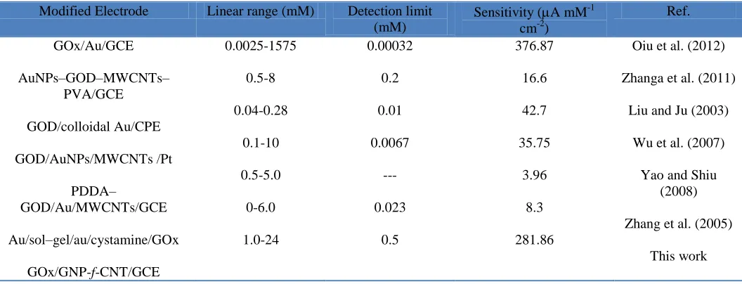
The RDE technique was employed for the detection of dissolved oxygen in 0.05 M pH 7 PBS. The rotation speed of GNP-f-CNT film modified GCE was set to be 1000 rpm and the reduction progress has been examined within the potential of +0.4 to -0.6 V with scan rate of 0.1 V/s. Curves (a)–(f) of Fig. 3(B) indicate that a linearly increases in the cathodic peak current at GNP-f-CNT/GCE for the increasing concentrations of dissolved oxygen (0 to 50 mg/L) in 0.05 M pH 7 PBS. The reduction peak current vs. concentration of the dissolved oxygen has been plotted and shown in the Inset of Fig. 3(B). The calibration plot is linear in the entire concentration range of 0 to 50 mg/L with R2=0.9981 for dissolved oxygen study with a sensitivity of 205.73 A L mg-1 cm-2. The detection limit and the relative standard deviation (RSD) for determining dissolved oxygen (n = 3) were found to be 0.5 mg/L and 2.8%, respectively. The linear range observed with GNP-f-CNT/GCE in this study is comparable with most of the other modified electrode reported in the literature [35-40] shown in Table 2. Also the GNP-f-CNT/GCE for the detection of dissolved oxygen is with a satisfied sensitivity as well.
Table 2. Comparison of sensing abilities for dissolved oxygen with different modified electrodes.
Modified Electrode Linear range (mM) Detection limit (mM)
Sensitivity (A mM-1 cm-2)
Ref. GOx/Au/GCE AuNPs–GOD–MWCNTs– PVA/GCE GOD/colloidal Au/CPE GOD/AuNPs/MWCNTs /Pt PDDA– GOD/Au/MWCNTs/GCE Au/sol–gel/au/cystamine/GOx
GOx/GNP-f-CNT/GCE
0.0025-1575 0.5-8 0.04-0.28 0.1-10 0.5-5.0 0-6.0 1.0-24 0.00032 0.2 0.01 0.0067 --- 0.023 0.5 376.87 16.6 42.7 35.75 3.96 8.3 281.86
Oiu et al. (2012)
Zhanga et al. (2011)
Liu and Ju (2003)
Wu et al. (2007)
Yao and Shiu (2008)
Zhang et al. (2005)
This work
3.4. The performance of the assembled glucose/O2 biofuel cell
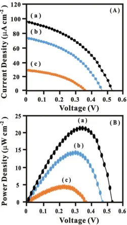
Fig. 4(A) displayed the polarization curves of the glucose/O2 BFC. Two components of the BFC included the bioanode based on the GOx/GNP-f-CNT modified GCE electrode and biocathode based on the (a) GNP-f-CNT/GCE, (b) GNP/GCE and (c) f-CNT/GCE were used. The anode compartment was containing 10 mM glucose and the cathode compartment was saturated with oxygen. The open-circuit voltage (Voc) of the BFC based on (a) GNP-f-CNT/GCE, (b) GNP/GCE and (c) f-CNT/GCE was 530, 470 and 355 mV, respectively. This difference may come from the difference of the reduction ability and potential of O2 at these three different biocathodes. The short-circuit current density (Jsc) of BFC with the f-CNT/GCE electrode increased 29.8 A cm−2 to 74.3 A cm−2
. For GNP electrodeposited on f-CNT/GCE electrode, the Jsc of the BFC increased to 98.7 A cm
Figure 4. (A) Polarization curves of biofuel cell based on (a) GNP-f-CNT, (b) GNP and (c) f-CNT biocathode. (B) Dependence of the power density on the cell voltage for biofuel cell. The condition is same as (A).
The power density curves of the BFC were shown in Fig. 4(B). To compare with (a) GNP-f-CNT/GCE electrode, the power density of (c) GNP-f-GNP-f-CNT/GCE electrode is increased apparently. For f-CNT depositions, power density of the BFC was only 4.7 W cm−2 at 224 mV. Power density of the BFC with the GNP/GCE electrode elevated to 14.1 W cm−2 at 285 mV. For comparison, the maximum power density of the BFC with the GNP-f-CNT/GCE electrode (curve a) was found 22.6W cm−2
[image:8.596.174.425.66.508.2]
dispersion of the enzyme. The combination of the glucose sensor based on the GOx/GNP-f-CNT/GCE and dissolved oxygen sensor based on the GNP-f-CNT/GCE can be considered as the components to enhance BFC performance.
4. CONCLUSION
A stable and simple film of GNP was successfully electrodeposited on f-CNT modified GCE surface for the dissolved sensor and applied to BFC on the biocathode. The GOx/GNP-f-CNT/GCE was act as a glucose sensor and applied to BFC on the bioanode. The surface analysis of the proposed film by FE-SEM shows that the f-CNT film supplied an uniformly network structure. The thus-prepared electrode for the construction of biofuel cell (BFC) was achieved up to 22.6 W cm-2 , and worked well as a biosensor for both glucose and dissolved oxygen with high sensitivity of 281.86 A mM−1 cm−2 and 205.73 A L mg−1 cm−2, respectively. The proposed protocol for synthesizing the GOx/GNP-f-CNT bionanocomposite is simple, convenient and fast in operation, which is expected to find wide biosensing and biofuel cell applications.
ACKNOWLEDGEMENTS
We acknowledge the Ministry of Science and Technology (project no. NSC982113M027006MY3 to Chen, 103-2410-H-182-020 to Lou) and OXY YOUNG Co., Ltd. provide the commercial drinking water products, Taiwan (ROC).
References
1. K. Rabaey, W. Verstraete, Trends in Biotechnology. 23 (2005) 291.
2. R.A. Bullen, T.C. Arnot, J.B. Lakeman, F.C. Walsh, Biosensors & Bioelectronics. 21 (2006) 2015. 3. F. Davis, S.P.J Higson, Biosensors & Bioelectronics. 22 (2007) 1224.
4. B.E. Logan, B. Hamelers, R. Rozendal, U. Schröder, J. Keller, S. Freguia, P. Aelterman, W. Verstraete, K. Rabaey, Environmental Science & Technology. 40 (2006) 5181.
5. S.C. Barton, J. Gallaway, P. Atanassov, Chem. Rev. 104 (2004) 4867.
6. A. Ramanavicius, A. Kausaite, A. Ramanaviciene, Biosensors & Bioelectronics. 20 (2005) 1962. 7. A. Heller, Acc. Chem. Res. 23 (1990) 128.
8. G.T.R. Palmore, H.H. Kim, J. Electroanal. Chem. 464 (1999) 110. 9. I. Willner, Y.M. Yan, B. Willner, R. Tel-Vered, Fuel Cells. 9 (2009) 7.
10.M.J. Cooney, V. Svoboda, C. Lau, G. Martin, S.D. Minteer, Energy Environ Sci. 1 (2008) 320. 11.E. Nazaruk, K. Sadowska, J.F. Biernat, J. Rogalski, G. Ginalska, R. Bilewicz, Anal. Bioanalytical
Chem. 398 (2010) 1651.
12.A.P. Periasamy, Y.J. Chang, S.M. Chen, S.M., Bioelectrochemistry. 80 (2011) 114. 13.A. Zebda, C. Gondran, P. Cinquin, S. Cosnier, Sens. Actuators B. 173 (2012) 760.
14.U. Salaj-Kosla, S. Pöller, Y. Beyl, M.D. Scanlon, S. Beloshapkin, S. Shleev, W. Schuhmann, E. Magner, Electrochem. Commu. 16 (2012) 92.
15.X. Wang, M. Falk, R. Ortiz, H. Matsumura, J. Bobacka, R. Ludwig, M. Bergelin, L. Gorton, S. Shleev, Biosensors & Bioelectronics. 31 (2012) 219.
17.Y. Lin, X. Cui, X. Ye, Electrochem. Commu. 7 (2005) 267. 18.C.C. Yang, A.S. Kumar, J.M. Zen, Electroanalysis. 18 (2006) 64.
19.H.F. Cui, J.S. Ye, W.D. Zhang, J. Wang, F.S. Sheu, J. Electroanal. Chem. 577 (2005) 295. 20.M.S. El-Deab, T. Sotomura, T. Ohsaka, Electrochim. Acta. 52 (2006) 1792.
21.J.S. Ye, Y. Wen, W.D. Zhang, H.F. Cui, L.M. Gan, G.Q. Xu, F.S. Sheu, J. Electroanal. Chem. 562 (2004) 241.
22.T.H. Tsai, S. Thiagarajan, S,M. Chen, Electroanalysis. 22 (2010) 680. 23.T.H. Tsai, S.H. Wang, S.M. Chen, J. Electroanal. Chem. 659 (2011) 69. 24.T.H. Tsai, S.H. Wang, S.M. Chen, Int. J. Electrochem. Sci. 6 (2011) 1655. 25.K.C. Lin, T.H. Tsai, S.M.Chen, Biosensors & Bioelectronics. 26 (2010) 608.
26.C.Y. Yang, S.M. Chen, T.H. Tsai, B. Unnikrishnan, Int. J. Electrochem. Sci. 7 (2012) 12796. 27.C. Qiu, X. Wang, X. Liu, S. Hou, H. Ma, Electrochim. Acta. 67 (2012) 140.
28.H. Zhanga, Z. Meng, Q. Wang, J. Zheng, Sens. Actuators B. 158 (2011) 23. 29.S. Liu, H. Ju, Biosensors & Bioelectronics. 19 (2003) 177.
30.B.Y.Wu, S.H. Hou, F. Yin, Z.X. Zhao, Y.Y. Wang, X.S. Wang, Q. Chen, Biosensors & Bioelectronics. 22 (2007) 2854.
31.Y.L. Yao, K.K. Shiu, Electroanalysis. 20 (2008) 1542.
32.S. Zhang, N. Wang, Y. Niu, C. Sun, Sens. Actuators B. 109 (2005) 367. 33.W. Orellana, Chem. Phys. Lett. 541 (2012) 81.
34.M. Vikkisk, I. Kruusenberg, U. Joost, E. Shulga, K. Tammeveski, Electrochim. Acta. 87 (2013) 709.
35.T.H. Tsai, S. Thiagarajan, S.M. Chen, Electroanalysis. 22 (2010) 680. 36.L. Wu, X. Zhang, H. Ju, Biosensors & Bioelectronics. 23 (2007) 479.
37.C.S. Martin, T.R.L. Dadamos, M.F.S. Teixeira, Sens. Actuators B. 175 (2012) 111.
38.R. de C.S. Luz, F.S. Damos, A.A. Tanaka, L.T. Kubota, Sens. Actuators B. 114 (2006) 1019. 39.M.S. Lin, H.J. Leu, C.H. Lai, Anal. Chim. Acta. 561 (2006) 164.