This is a repository copy of
Design, microstructure and mechanical characterization of
Ti6Al4V reinforcing elements for cement composites with fractal architecture
.
White Rose Research Online URL for this paper:
http://eprints.whiterose.ac.uk/147640/
Version: Published Version
Article:
Farina, I., Goodall, R. orcid.org/0000-0003-0720-9694, Hernández-Nava, E. et al. (3 more
authors) (2019) Design, microstructure and mechanical characterization of Ti6Al4V
reinforcing elements for cement composites with fractal architecture. Materials & Design,
172. 107758. ISSN 0261-3069
https://doi.org/10.1016/j.matdes.2019.107758
[email protected]
https://eprints.whiterose.ac.uk/
Reuse
This article is distributed under the terms of the Creative Commons Attribution-NonCommercial-NoDerivs
(CC BY-NC-ND) licence. This licence only allows you to download this work and share it with others as long
as you credit the authors, but you can’t change the article in any way or use it commercially. More
information and the full terms of the licence here: https://creativecommons.org/licenses/
Takedown
If you consider content in White Rose Research Online to be in breach of UK law, please notify us by
Design, microstructure and mechanical characterization of Ti6Al4V
reinforcing elements for cement composites with fractal architecture
Ilenia Farina
a, Russell Goodall
b, Everth Hernández-Nava
b, Andrea di Filippo
c,
Francesco Colangelo
a,⁎
, Fernando Fraternali
caDepartment of Engineering, University of Naples“Parthenope”, Naples, Italy bDepartment of Materials Science & Engineering, University of Sheffield, UK cDepartment of Civil Engineering, University of Salerno, Italy
H I G H L I G H T S
•A general procedure for the design of re-inforcing elements with fractal architec-ture is presented.
• Physical models of Koch fibers and meshes are additively manufactured through electron beam melting. •The accuracy of the reproduction of
frac-tal geometries through additive manufacturing is investigated. • The mix design and the mechanical
characterization of a cement mortar to be reinforced with Kochfibers are given. •Bending tests on mortar specimens re-inforced with Kochfibers show marked matrix-rebar interlocking effects.
G R A P H I C A L A B S T R A C T
a b s t r a c t
a r t i c l e
i n f o
Article history:
Received 11 February 2019
Received in revised form 22 March 2019 Accepted 22 March 2019
Available online 29 March 2019
This paper presents a study on the design, and microstructural and mechanical characterization of additively manufactured reinforcing elements for composite materials exhibiting fractal geometry, with a focus on the flex-ural reinforcement of cement-matrix composites. The examined elements are manufactured via an additive pro-cess, electron beam melting, from the Ti6Al4V titanium alloy, using a Koch curve construction ruled by three complexity parameters. Kochfibers and meshes are designed, additively manufactured and experimentally tested, through the use of the proposed fractal design procedure. Laser scanning tests illustrate the correspon-dence between the CAD objects and the additively manufactured samples. The experimental characterization of the surface properties of the Kochfibers is conducted through optical microscopy and contact angle tests, while their mechanical performance is analyzed through Vickers hardness and bending tests on afi ber-reinforced ber-reinforced mortar. The given mechanical tests highlight that reinforcingfibers with fractal architecture significantly enhance thefirst crack strength and the residual loading capacity of cement mortar specimens sub-ject to three-point bending tests. This is due to the relevant interlocking mechanisms acting at the interface be-tween the matrix and the ribs of such reinforcing elements, which delay the macroscopic cracking of the mortar. © 2019 The Authors. Published by Elsevier Ltd. This is an open access article under the CC BY-NC-ND license (http:// creativecommons.org/licenses/by-nc-nd/4.0/).
Keywords:
Fractal geometry Koch curve Fractal interlocking Additive manufacturing Titanium alloy
⁎ Corresponding author.
E-mail addresses:[email protected](I. Farina),r.goodall@sheffield.ac.uk(R. Goodall),e.hernandeznava@sheffield.ac.uk(E. Hernández-Nava),andrea.difi[email protected]
(A. di Filippo),[email protected](F. Colangelo),[email protected](F. Fraternali).
https://doi.org/10.1016/j.matdes.2019.107758
0264-1275/© 2019 The Authors. Published by Elsevier Ltd. This is an open access article under the CC BY-NC-ND license (http://creativecommons.org/licenses/by-nc-nd/4.0/).
Contents lists available atScienceDirect
Materials and Design
1. Introduction
The development of novel materials fabrication processes is attracting growing interest from scientists and engineers towards architected materials and structures [1]. Recent advances in materials science have made increasingly possible the design of hierarchical ele-ments exhibiting advanced mechanical properties at different scales [2–10]. Particularly interesting are the effects created by a hierarchical design of multiscalefibers coated with carbon nanotubes and different nanofibers, which have been proven to markedly enhance the interlam-inar shear strength of multiscale composites [11–15]. Significant im-provements in mechanical properties have also been observed in the presence of nanoscale coating on microlattices [16], nested hierarchical wrinkling patterns on polymeric surfaces created through plasma treat-ment [17], and a variety of other different surface treatments [18–19].
It is known that most natural materials exhibit hierarchical organiza-tion of matter and fractal geometries, which provide increased surface area for the same volume of material [20]. Fractal geometry indeed per-mits the design of hierarchical patterns through self-similar subdivi-sions of basic shapes such as squares or triangles. This subdivision process can be repeated an infinite number of times, obtaining increas-ingly complex structures that exhibit fractal dimensions much greater than their topological dimensions [20–23]. Fractals have been employed in a large variety offields, including biology, economy, bio-architecture, electrical engineering, and in a number of different technologies (refer, e.g., to [24] and references therein). Particularly interesting is the fractal modeling of fractures and sutures in engineering and biological systems, as well as the fractal description of the topological interlocking occur-ring in architectured materials that are obtained by joining similar or dissimilar materials through interfaces with complex geometry [24–26]. The application of fractal concepts for the design of multiscale reinforcingfibers of composite materials, however, has not been signif-icantly explored at the current date, with the exception of a few, limited scope examples, concerned, e.g., with tissuefiber scaffolds for biological applications [27].
Generally, the design of new objects relies on two main features, the chemical composition of the material and the morphological structure of the object. While the chemical composition is an intrinsic property of materials, their morphology and surface roughness can be artificially modified through suitable treatments that induce hierarchical architec-tures [19,20]. Surface treatments and coatings have been employed to design hierarchical structures based on carbon nanotubes [21,22] exhibiting an increase in fracture toughness; nanofibers featuring an in-creased redistribution of the load and thus improving the mechanical performance of each hierarchical system [1,24]; andfilms showing im-proved bonding and fracture toughness [25–27].
Additive manufacturing (AM) is currently the most common tech-nique for fabricating architectured materials exhibiting advanced func-tionalities not found in conventional materials at different scales [28–29]. A large variety of additive manufacturing processes are avail-able from the nanometre to the centimetre scale, such as stereolithography, laser sintering polyjet, x-ray lithography, electron beam melting and atomic layer deposition, to name just a few examples (while in some instances these processes are referred to as3D printing, here we use the termAdditive Manufacture,AM). AM has made possible the fabrication of fractal shapes directly from computer-aided design (CAD) data, using metallic (steel, aluminum, titanium, etc.), polymeric (polypropylene, polyethylene terephthalate, etc.), natural (flax, jute, kenaf, etc.), recycled (plastic, glass, metals, rubbers, cellulose, etc.), and innovative industrial materials (carbon-based materials, etc.) [28–29].
Examples of hierarchical materials in civil engineering include rein-forcing elements of cement mortars or concretes, to be employed for the fabrication of building materials with enhanced strength and fracture toughness [2–4,30]. The longitudinal and transverse profiles of such el-ements must be adapted to the size of the aggregates, with the aim of
obtaining an optimal adhesion between reinforcingfibers and meshes and the matrix material [31].
We deal in the present paper with the design, additive manufactur-ing and experimental characterization of architectured reinforcmanufactur-ing ele-ments for composite materials that exhibit fractal geometry, with a focus on cement matrix composites. The presented study significantly generalizes the research presented in Refs. [2–4] on the additive manufacturing of reinforcing elements with multiscale surface texture, by developing a general design procedure forfibers and meshes that employs the Koch curve concept at different scales [20]. In addition, the present work enriches the results given in [2–4] by investigating the accuracy of the additive manufacturing process in metallic materials applied to the examined reinforcements, and through an experimental study of the influence played by the level of complexity of such ele-ments on theflexural response of afiber-reinforced mortar.Section 2 of the manuscript illustrates the proposed fractal design algorithm, to-gether with a variety of“Koch”fibers and meshes that it allows to be generated. Next,Section 3describes afirst approach to the AM of phys-ical samples of such reinforcing elements in metallic materials, which consist of reinforcingfibers (or rebars) featuring fractal cross-section boundary, and meshes formed by weaving wires that exhibit fractal lon-gitudinal profile. The examined samples are fabricated in the Ti6Al4V ti-tanium alloy, through electron beam melting (EBM), employing the Arcam EBM Q20 plus facility available at the Department of Materials Science and Engineering of the University of Sheffield. We employ EBM in the present study with the aim of contributing to the active area of research of the cement industry that is oriented to the use of 3D printed metallic reinforcements of construction materials. While we note that this process, and the titanium alloy selected, are relatively high cost compared to current rebar processing technology and mate-rials, developments are being made in Additive Manufacture of metallic reinforcements of construction materials [32] and in the AM processing of large structures for civil engineering in general (such as the 3D printed bridge developed by MX3D, set to be installed in Amsterdam this year [33]), and this work contributes to that area of research. EBM and Ti6Al4V were chosen for this initial study as these are a well-established method and material, meaning that the results are less likely to be influenced by unknown processing factors.Sections 4 and 5of this paper respectively describe the 3D digitization of the AM samples, and the microstructure characterization of such elements. Mechanical and physical tests on the AM samples are presented inSection 6. The Discussionsection (Section 7) examines the potential of such elements when acting as reinforcements of novel mortar and concrete compos-ites. Concluding remarks and directions for future work are outlined in Section 8.
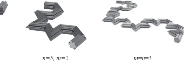
2. Fractal design algorithm for reinforcingfibers and meshes
Fractalfibers and meshes can be designed in a simple and straight-forward way through an algorithm based on the Koch curve concept [20–23] and three complexity parameters (or orders)n,mandp.Fig. 1 illustrates the“Koch algorithm”that we employ in the present work. Thefirst complexity parameternat the basis of this algorithm is related to the fractal dimension of the boundary of the cross-section of the ele-ment. This parameter counts the number of self-similar divisions of the equilateral triangle corresponding ton= 0, which produce a Koch snowflake in the limitn→∞[21]. The second complexity parameter mcontrols the numbers of the iterations of the Koch curve that we em-ploy on afixed segment of the longitudinal profile of thefiber (Fig. 1). Finally, the third complexity parameterpcounts the numbers of copies of such a segment that we employ along the longitudinal span of the el-ement. We hereafter name Kochfibers the shapes generated according to the algorithm presented inFig. 1, implicitly intending that such a no-menclature is rigorous only in the limiting cases withn,m→∞. 3D CAD models of Kochfibers corresponding to differentfinite complexitiesn andm(assumingp= 1) are given inFig. 2.
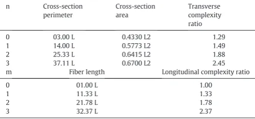
We refer the reader to Refs. [20–23] for the computation of the fractal measures of the surfaces and lines generated by the algorithm in Fig. 1. For technical purposes, it is useful to introduce two complexity ratios associated with the geometry of the lateral surface of the Kochfibers. Thefirst of these quantities is defined as the ratio between the perimeter of the cross-sections of a Kochfiber and the circumference of a circle having same area (transverse complexity ratio). The second complexity ratio instead relates the length of the longitudinal profile of a Kochfiber formN0 with the length of the
rectilinear segment corresponding tom= 0 (longitudinal complexity
[image:4.595.101.517.71.463.2]ratio).Table 1shows the complexity ratios of Kochfibers featuring different ordersnandm. Forn=m= 3, it is observed that the Kochfiber has cross-section perimeter 2.45 times larger than the perimeter of a circularfiber with equal cross-section area. The samefiber has also longitudinal length 2.37 times larger than the length of a straightfiber. This implies that the measure of the lateral surface of the Kochfiber under consideration is equal to (2.45 × 2.37) 5.81 times the measure of the lateral surface of a circular cylinder of equal volume. Similar but less pronounced results are obtained for lower values of the ordersnandm(cf.Table 1).
Fig. 1.Fractal algorithm based on the Koch curve and three complexity parametersn,mandpto generate the cross-section (A) and the longitudinal profile (B) of reinforcing elements with fractal geometry.
Fig. 2.3D views of Kochfibers for different complexities.
[image:4.595.187.496.622.727.2]The Koch algorithm illustrated so far can be generalized in a number of ways, in order to suitably design a large variety of fractalfibers and meshes, whichfit different technical applications. Afirst generalization
of the basic Koch algorithm is obtained by recourse to the (q,c)-Koch curve concept [21]: starting with a regular polygon of sideL, one can re-place the middlecLportion of the generic side with a regular polygon featuringqsides,cdenoting a positive numberb1. Such a division
[image:5.595.34.284.86.203.2]pro-cess can be recursively applied to the segments of the newly generated polygon, creating a fractal shape.Fig. 3a shows three iterations of such a construction, forq= 6 andc= 1/3. The second generalization of the Koch algorithm regards the directionality of the division process, that is the side towards which the recursive divisions of the edges of the Koch curve are applied. The subdivision“side”can be suitably switched during the division process on selected portions of the Koch curve, giv-ing rise to“balanced”fractal profiles (facing partially upward and par-tially downward). A third generalization is concerned with the possibility to join segments of (q,c)-curves corresponding to different values ofqandcand different complexities, in order to form“ compos-ite”fractal shapes. Such a joining process can also make use of rotations and folding of the above segments, and may profit from the random composition of fractal shapes.Fig. 3b shows the longitudinal profile of Table 1
Complexity ratios of Kochfibers (Ldenotes one third of the length of the closed/open line segment corresponding ton= 0/m= 0).
n Cross-section perimeter
Cross-section area
Transverse complexity ratio
0 03.00 L 0.4330 L2 1.29
1 14.00 L 0.5773 L2 1.49
2 25.33 L 0.6415 L2 1.88
3 37.11 L 0.6700 L2 2.45
m Fiber length Longitudinal complexity ratio
0 01.00 L 1.00
1 11.33 L 1.33
2 21.78 L 1.78
3 32.37 L 2.37
Fig. 3.Composite Kochfibers and meshes.
[image:5.595.79.504.257.741.2]a composite Kochfiber, whileFig. 3c and d show meshes obtained by crossing composite Kochfibers. Finally,Fig. 3e shows a cylinder ob-tained by rolling a Koch mesh along a side. It is worth observing that the transverse diameter of the generic edge of a Kochfiber cannot ex-ceed its longitudinal length, which introduces a dependence of the transverse scale of thefiber over the longitudinal scale. The hierarchical organization of the interface between a Koch reinforcement and the sur-rounding matrix material is discussed in Section 0.
3. Additive manufacturing of physical samples
Due to the technological challenge of additively manufacturingfi ne-scale hierarchical Kochfibers in metallic material, in this study we focus our attention on the fabrication of Kochfibers of the following simple types: Kochfibers (or bars) with straight longitudinal profile and fractal cross-section, for varying complexitiesn, and a Koch mesh formed by a grid of composite Kochfibers with circular cross-section and fractal lon-gitudinal profile.
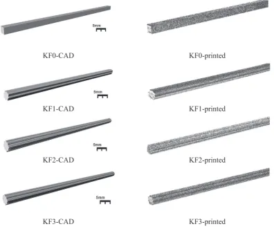
Fig. 4shows the CAD models and AM samples of the analyzedfibers, which include a squarefiber with edge length L0= 5.32 mm (labeled
KF0), and three Kochfibers KF1, KF2 and KF3. The latter are obtained by applying the Koch algorithm with complexitynequal to 1, 2 and 3, respectively, to the sides of squares with edge lengths L01= 5.05 mm,
L02= 4.98 mm, and L03= 4.95 mm. The distance between two
succes-sive vertices of the KFn cross-section boundary is computed as follows: Ln= (1/3)nL0n[21,22], and it is easily verified that it results in L1=
1.68 mm, L2= 0.55 mm, and L3= 0.18 mm. The last two of these
lengths approach the resolution limits for processing by this technique in metal; it has been reported that the dimensions of heat sources used in AM fall within this range [30]. All the examinedfibers exhibit equal cross-sectional area A = 28.35 mm2, and 160 mm length (giving
the volume: VKF= 4536 mm3), which correspond to 6.01 mm
equiva-lent diameter. The morphology of the cross section of the 3D printed bar KF3 is illustrated inFig. 5. The image inFig. 5and the microstructure characterization presented inSection 5employ an optical microscope (OM) Nikon eclipse LV150 with crossed polarized light imaging capability.
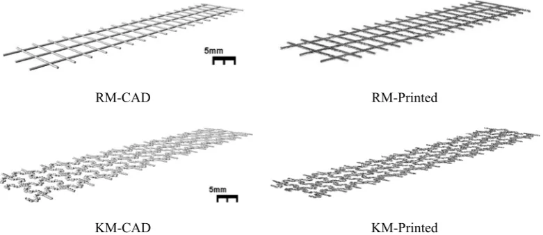
The examined meshes are illustrated inFig. 6. A simple rectangular mesh (RM) with 8.11 mm × 11.79 mm spacing and cylindrical wires of 0.86 mm diameter is analyzed in comparison with a Koch mesh (KM). The latter is equipped with composite Koch wires featuring cylin-drical cross-section with 0.59 mm diameter, and a fractal longitudinal profile. The distance between consecutive vertices of such a profile ranges from a maximum value of 1.12 mm down to a minimum value of 0.17 mm. The width of the RM and KM samples is 35 mm, while their length is 155 mm. The total volume of the Koch mesh is VKM=
624.92 mm3, while that of the square mesh is V
RM= 628.93 mm3. We
refer the reader toFig. 6for a graphical illustration of the architecture of the Koch mesh.
[image:6.595.107.504.399.733.2]Additive Manufacturing processes often produce samples with an-isotropy in their underlying defect structure and microstructure, due to the directional way the material is built up. Here STLfiles (provided in the Appendix) were orientated in such a way to additively manufac-ture the samples they defined at the best possible resolution and with the lowest possible concentration of defects. To do this, an orientation parallel to the build direction was used for rods and an orientation at 45° to the build direction for mesh samples; the latter configuration was intended to avoid preferential defect location in thin members [31]. All samples were manufactured using a Q20 plus ARCAM system with prealloyed Ti-6Al-4 V plasma atomised powder deposited in 50 μm thick layers, using the process parameters described in the Appen-dix. We additively manufactured nine samples of each analyzedfiber
Fig. 4.CAD models and 3D printed samples of the analyzed Kochfibers.
and mesh. Careful examination of the samples produced was needed, since the size of the EBM-built objects can be affected by the inherent surface roughness (and its effect on resolution) if manufacturingfine features is attempted, or by solidification shrinkage effects for larger ones. When compared with the CAD models the actual dimensions may therefore vary. As mentioned before, minimum achievable feature sizes in this system of ~0.4 mm are estimated based on similarfindings in literature [30–40]. With such variances from the design, we accept that the AM samples of the Kochfibers and the Koch mesh do not ex-actly match the theoretical geometries described above, especially in the case of the KF3fiber and the Koch mesh KM (seeFig. 4); the issue of the accuracy of the AM parts is addressed in the next section of the manuscript.
4. 3D laser scanner surveys
The accuracy of the employed Additive Manufacturing process was assessed by measuring the deviations between the geometry of an AM specimen and that of the corresponding master CAD model, for all the samples illustrated inFigs. 4 and 6. Such a graphical comparison test was conducted by capturing the 3D shape of each EBM-built object through a 3D digitizer. The small features exhibited by the examinedfi -bers and meshes (cf.Section 3) were captured through the non-contact
3D scanner VIVID 910 by Konica Minolta [41–42]. After the scanning of the 3D printed parts, the digitized images produced by the VIVID 910 built-in software (cf. the Appendix) were exported to the STL format. The digitized STL (DSTL) mesh of each analyzed object was next imported into the Geomagic Studio 2014 software [43], together with the STLfile of the CAD drawing (CSTL). Thefirst phase of the graphical comparison test consisted of the alignment between the DSTL and CSTL models. Such a process was divided into two steps: afirst rough alignment based on point picking, followed by a best-fit alignment ob-tained through an iterative closest point algorithm [41], always taking the CSTL model as reference. The second phase resulted in the genera-tion of three-dimensional, color-coded maps of the deviagenera-tions observed between the positions of the parent vertices of the DSTL and CSTL models, which were determined through the algorithm illustrated in the Appendix.
Table 2illustrates the statistics of the tests run between the exam-ined DSTL and CSTL models. It is worth observing that the distances be-tween parent vertices of the such models can be either positive or negative, being oriented along the outward normal to the external sur-face of the CSTL model (cf. the Appendix). In the case of the Kochfibers and meshes, the rightmost column ofTable 2gives the relative error de-fined by the ratio between the Root Mean Square (RMS) deviation be-tween CSTL and DSTL models and the minimum CSTL feature (minimum distance between adjacent vertices).
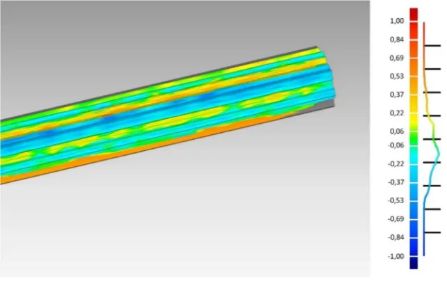
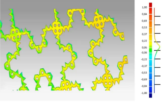
[image:7.595.60.259.52.250.2]The color maps of the oriented distance errors between the CSTL and DSTL models of the KF2 bar and the Koch mesh KM are reported in Figs. 7 and 8, respectively. The analogous maps relative to the KF1 and KF3 bars are provided in the Appendix. The results inTable 2highlight that the minimum deviations between the CSTL and DSTL models are observed with reference to the KF0fiber (cf.Fig. 7). The fractalfibers KF1 and KF2 show greater RMS errors and relative errors, as compared to KF0. Finally, the KF3fiber and the fractal mesh KM exhibit smaller RMS errors and greater relative errors over the KF1 and KF2fibers. The maximum CSTL-DSTL deviations were observed in correspondence with the folds of the AM objects (cf.Figs. 7, 8and the Appendix). It is worth noting that the relative errors associated with the KF3 (90.05%) and KM (75.99%) elements are markedly high, since the oriented dis-tances between the CSTL and DSTL vertices of such objects are of the same order of magnitude as the size of the minimum features of the CSTL models. We recall that the KF3 bar and the KM grid display mini-mum features of the order of 0.2 mm, which go markedly below the minimum achievable feature sizes of the employed ARCAM EBM facility (~0.4 mm), as we already observed inSection 3. Overall, the results in Table 2reveal that an accurate additive manufacturing of the Kochfi -bers and meshes exhibiting high complexity calls for the adoption of equipment with higher accuracy than the ARCAM Q20 facility employed in the current work.
[image:7.595.102.493.558.727.2]Fig. 5.Optical microscope image showing the“as-built”cross section of Koch bar KF3 with an equivalent diameter of 6.01 ± 0.2 mm. Blue insert bars representing regions of KF2 bar are shown for reference. (For interpretation of the references to color in thisfigure legend, the reader is referred to the web version of this article.)
Fig. 6.CAD models and 3D printed samples of a rectangular mesh (RM) and a Koch mesh (KM).
5. Microstructure characterization
The“as-built”material microstructure was characterized through optical microscopy. Sample preparation began by cutting the material, which was then mounted in bakelite for further surface preparation, using standard methods which are described elsewhere [30]. The obser-vations under OM showed a microstructure composed of afine plate morphology and traces of columnar grains, seeFig. 9. This type of micro-structure inα+βTi-6Al-4 V titanium alloy produced by EBM has been reported extensively in previous work in thefield [34–35].
The microstructural features observed (both here and in earlier work) develop from thefirst columnar grains (β-phase) which form im-mediately on solidification. On cooling to room temperature there is a transformation to anα+βmicrostructure, with some of the prior mi-crostructure remaining visible, accompanied byα-phase formed by the allotropic transformation. As the cooling rates are relatively fast in AM processes [36], the transformation is rapid and diffusionless, and the mi-crostructure developed is in the form offine plates, with their thickness reported to be inversely proportional to the cooling rate. The mechani-cal properties of Ti6Al4V have been reported extensively in terms of their variation with this plate size [37]. Fine grain morphologies (effec-tively the case if the plates are small) impede the motion of dislocations going through the material, and sofiner microstructures are usually cor-related with high resistance to permanent deformation [37]. In this work,fine plate microstructures can be observed from bar and mesh samples, seeFig. 9.
6. Mechanical and physical tests
6.1. Vickers hardness
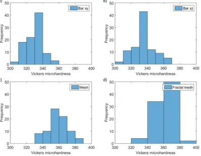
Although quantification of the length scale in relation to dislocation motion in these complex microstructures is not straightforward, Vickers hardness values of bar and mesh samples are shown inFig. 10. Vickers
hardness was carried out using a Struers Durascan 70 automated denter. Prepared surfaces used for metallographic observations were in-dented with 0.1 kg of load in 10 × 10 arrays with 0.1 mm spacing and 5 s of dwell time. It can be seen that mesh samples show relatively higher hardness values, suggesting higher strength properties in general (ap-proximately ~1030 MPa, as the hardness of metals can be related in a general way to yield strength [38]), due to the faster cooling rates [39] which are easily generated in such low thermal mass components.
6.2. Contact angle tests
Contact angles tests have been run on the AMfibers shown inFig. 4 in order to study the interaction of the surface roughness induced by the EBM deposition process [30] with the fractal geometry of such elements. It is well known that contact angle tests executed on sessile liquid drops deposited on a solid surface allow for an effective and easy characteriza-tion of the surface through its wettability (refer, e.g., to [40–46] and ref-erences therein). Different results are obtained when running such tests on smooth and rough surfaces, since the apparent (or experimental) contact angleϑ* of the deposited liquid drop on a non-smooth surface is strongly affected by the surface roughness and the phenomenon of contact angle hysteresis [40–46].
[image:8.595.42.562.78.147.2]We performed ten optical contact angle tests on thefibers shown in Fig. 4, through the OCA System 20 apparatus distributed by DataPhysics Instruments [47]. Such tests were carried out by dropping 1μl water drops on the lateral surface of thefiber. The mean values and standard deviations of the contact angle measurements are provided inTable 3 (see the Appendix for the pin-sharp drop images recorded for the sam-ples under testing). The results inTable 3highlight that all the measured contact angles areN90°, and that the mean value ofϑ* is slightly greater for the Kochfibers KF1, KF2 and KF3, than the squarefiber KF0. In par-ticular the mean value ofϑ* for KF3 is only 3.5% different from the mean value of the same quantity referred to the squarefiber KF0. We are led to conclude that the surface roughness of the AM Kochfibers is Table 2
Statistics of the graphical comparison tests between CSTL and DSTL models.
Object Max. distance + (mm)
Max. distance−
(mm)
Average distance (mm)
Average distance + (mm)
Average distance−
(mm)
Standard deviation (mm)
RMS estimate (mm)
Min. feature (mm)
Relative error (%)
KF0 0.51 −0.40 0.05 0.10 −0.05 0.10 0.11 5.33 2.06
KF1 0.65 −0.83 −0.06 0.10 −0.16 0.17 0.18 1.68 10.51
KF2 0.76 −0.79 −0.07 0.17 −0.20 0.22 0.23 0.55 41.83
KF3 0.81 −0.51 0.02 0.14 −0.11 0.16 0.17 0.18 90.05
[image:8.595.143.465.526.728.2]KM 0.72 −0.54 0.07 0.11 −0.07 0.11 0.13 0.17 75.99
Fig. 7.GC test on the Koch bar KF2: ±max = 0,76/−0,79 mm; ±average = 0,17/−0,20 mm; standard deviation = 0,22 mm; RMS estimate = 0,23 mm.
not dramatically affected by the fractal geometry in the design of such elements. This in turn implies that the EBM deposition process (i.e. powder raw materials used), influences and retains, up to some point, a surface performance when processing parts with the geometries of the Kochfibers.
6.3. Bending tests on mortar specimens reinforced with Kochfibers
We conducted a study on the strengthening ability of the reinforce-ments analyzed in the present study by running three-point bending tests on prismatic 40 mm × 40 mm × 160 mm mortar specimens rein-forced with KF0, KF1 and KF2fibers/bars. The European standard EN 1015-11:2007 [48] was employed to run such tests, using a MATEST electrically operated testing machine with 200 kN capacity [49]. The KF3 bars and the KM grid illustrated inSection 3were not included in the present study, due to the limitations of the employed EBM technol-ogy in manufacturing parts with minimum feature sizes. As we already noted inSection 4, these limitations are determined by factors such as the heat source spot size and powder size distribution.
We analyzed a mortar that employs 80% (weight) Portland cement and 20%fly ashes as binders, in association with 80% ground granulated blast furnace slag and 20% marble slag as aggregates (water/binder ratio equal to 50%). Such industrial by-products provide economic and
environmental benefits and enhance cohesiveness of the matrix [50–51]. Thefine-size marble slagfiller indeed minimizes the internal friction and facilitates the particle distribution, leading to improved workability of the mixture. The mix design of the employed mortar is il-lustrated inTable 4. Mortar specimens were cast in 160 × 40 × 40 mm molds with embedded fractal rebars. The molds werefilled in two stages. In thefirst stage, a layer of mortar was poured up to 12 mm height (net mortar cover of thefibers), making use of a mechanical mixer. Next, the reinforcing bars were placed into the mold, and addi-tional mortar was poured until the mold wasfilled. The mortar was compacted using a mechanical mixer and the specimen was leveled with a trowel. Finally, the specimens were cured while sealed within the molds at 40 °C for 24 h, and unsealed, after mold removal, for addi-tional 27 days at room temperature before testing.
The mechanical characterization of the unreinforced (UNR) mortar was carried out by testing four cubic specimens with 40 mm edge length. Ultrasonic tests conducted through a portable ultrasonic nonde-structive tester (test procedure illustrated in [52]) lead us to estimate the following mean value of the dynamic modulus of elasticity of the mortar:Edm= 14.29 GPa, (5.97 GPa standard deviation), while uniaxial
compression tests estimated a mean compressive strengthfcm =
[image:9.595.134.455.54.256.2]14.50 MPa (4.68 MPa standard deviation). We reinforced three different mortar specimens with AM processed exemplars of the KF0, KF1 and Fig. 8.GC test on the Koch mesh KM: ±max = 0,72/−0,54 mm; ±average = 0,11/−0,07 mm; standard deviation = 0,11 mm; RMS estimate = 0,13 mm.
Fig. 9.Microstructural morphology composed offine alpha plates. (a) KF3 sample in the build direction showing columnar grain boundaries andα-plates. (b) Fractal mesh sample showing fineα-plates.
[image:9.595.125.465.550.718.2]KF2fibers, and, in addition, conducted bending tests also on three unre-inforced mortar specimens. The three-point bending tests were exe-cuted on a clear lengthL= 100 mm, using a 0.50 mm/min loading rate. LetFandδrespectively indicate the transverse force applied at the center of the specimen and the midspan deflection, and letσ¼3FL
2a3 de-note a reference axial stress, which corresponds to the stress acting at the extremefibers of the cross-section in the uncracked regime. The F vs.δandσvs.δresponses of all the analyzed specimens are graphically illustrated inFig. 11, while pictures taken during and after the bending tests on selected specimens are presented inFig. 12. TheF-δandσ-δ curves shown inFig. 11exhibit an initial linear branch for small values ofδ, which is followed by a nonlinear branch exhibiting progressively decreasing slope. Such a branch terminates with critical points C≡(δcr, Fcr) and C′≡(δcr,σcr), where the F vs.δandσvs.δcurves exhibit marked force and stress drops, respectively, due to the onset of a macroscopic crack at the bottom edge of the specimen near the midspan. The post-critical behavior is characterized by a nearly horizontal plateau of the above curves, describing the response of the fractured material. This mechanical behavior originates from the formation of diagonal cracks at the supports (typically at one support, as in most of the present ex-amples, but possibly also at both supports), which add to the initial crack, and are accompanied by subsequent additional cracks in the
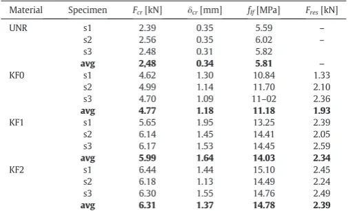
region between the midspan and the supports. The described crack pat-tern leads to the diffuse crushing of the mortar, andfinally to failure of the material (cf.Fig. 12). The statistics of the bending tests are given inTable 5, whereFcrdenotes the value ofFat the critical point;fIf= σcrdenotes thefirst crack strength of the material; andFresdenotes the average value of the residual load-carrying capacity in the loading interval betweenδ=δcrandδ=5 mm. Referring to the average values, one observes 154% and 31% increases ofFcrandfIfin KF2-reinforced specimens, over UNR and KF0 samples, respectively. The value ofFres in KF2 specimens is 37% higher than that exhibited by KF0 samples, while such a quantity is practically zero in the unreinforced mortar (Fig. 11). Significant increases in the average ofFcr,fIfandFresare also ob-served when passing from KF2 to KF1 specimens (cf.Table 5).
[image:10.595.106.504.56.364.2] [image:10.595.313.563.682.743.2]With reference to cement matrix composite structures loaded in bending, there is a large body of experimental evidence that the re-sponse of the tension tie-rods active in such structures is characterized by the bond behavior, affected by adhesion, friction and interlocking [53–55]. The rebar-matrix slip law initially shows a linear shape, as long as the adhesion between such elements prevails over friction and interlocking. This initial response is followed by a nonlinear branch of the tangential stress (tau) vs. slip curve, due to the onset of more signif-icant bar-matrix slipping. The nonlinear branch is associated with the micro- and macro-cracking of the interface, and appreciable Fig. 10.Histograms showing Vickers microhardness values from; (a) KF3 bar sample in cross sectional area; (b) KF3 in the build direction; (c) RM sample; (d) KM sample.
Table 3
Mean values and standard deviations of the contact angle measurements.
Fiber-type ϑ* (°)
Mean ± St.Dev.
KF0 109.3 ± 7.6
KF1 109.6 ± 6.9
KF2 112.9 ± 6.8
KF3 113.1 ± 7.7
Table 4
Mix-design of the employed mortar specimens.
Component Dosage
Portland cement (binder) 360 g
Fly ash (binder) 90
Ground granulated blast furnace slag (aggregate) 1080 g
Marble slag (aggregate) 270 g
Water 225 g
[image:10.595.82.256.683.744.2]interlocking and friction effects. The peak of the tau-slip curve marks a critical equilibrium point, which is followed by a softening response of the material up to failure, due to the spalling of the matrix produced Fig. 11.Force- and stress-deflection curves of the unreinforced mortar specimens (UNR), and the specimens reinforced with KF0, KF1 and KF2fibers.
[image:11.595.301.554.85.238.2]Fig. 12.Pictures taken during the bending tests on selected specimens (top), and after the failure of a KF2 sample (bottom). Table 5
Experimental values of the peak load (Fcr), the midspan deflection (δcr) corresponding to
Fcr, thefirst crack strength (fIf), and the residual load (Fres) measured during bending tests. Material Specimen Fcr[kN] δcr[mm] fIf[MPa] Fres[kN]
UNR s1 2.39 0.35 5.59 –
s2 2.56 0.35 6.02 –
s3 2.48 0.31 5.82
avg 2,48 0.34 5.81 –
KF0 s1 4.62 1.30 10.84 1.33
s2 4.99 1.14 11.70 2.10
s3 4.70 1.09 11–02 2.36
avg 4.77 1.18 11.18 1.93
KF1 s1 5.65 1.95 13.25 2.39
s2 6.14 1.45 14.41 2.05
s3 6.17 1.53 14.45 2.59
avg 5.99 1.64 14.03 2.34
KF2 s1 6.44 1.44 15.10 2.45
s2 6.18 1.13 14.49 2.24
s3 6.30 1.55 14.76 2.49
avg 6.31 1.37 14.78 2.39
[image:11.595.125.464.267.728.2]by the ribs of the rebars (see, e.g., [55] and references therein). The tie-rod response in presence of appreciable interlocking effects is markedly influenced by the texture of the rebars [53–56]. Some different failure modes may also occur, due, e.g., to pull-out failure, bar rupture, concrete cover failure, etc., which are not of interest in the present case [56].
The visual inspection of the experimental response of the mortar specimens analyzed in the present study confirms the above experi-mentalfindings, and highlights that such specimens exhibit a strut-and-tie mechanism in the fracture regime [57]. This resisting mecha-nism is formed by compressed diagonals, a top chord member, and a bottom tension-tie rod (cf.Fig. 12). In particular, one observes that the F−δresponse of the KF0 specimens exhibits a nearly linear profile up to the critical point (Fig. 11), which means that the strut-and-tie mech-anism is mainly effective only in the post-critical regime in the present case (cf.Fig. 12-top). By contrast, theF−δcurves of the KF1 and KF2 specimens show a markedly nonlinear shape before the critical force drop occurs, due to the onset of significant slipping and interlocking phenomena already occurring under the pre-critical conditions (Fig. 12-center/bottom).
A theoretical estimate ofFcrcan be obtained by assuming perfect ad-hesion between the reinforcingfiber and the mortar in the pre-critical regime, making use of the following formula for the maximum tensile stress supported by the undamaged material [2].
ft¼ FcrL=4
I ða−xÞ: ð1Þ
In Eq.(1),Iis the moment of inertia of the full-resistant cross-section, andxis the depth of the neutral axis. The adoption of standard homogenization techniques [58] leads us to predict
x¼n Abþn
0a2
að1−n0Þ −1þ
ffiffiffiffiffiffiffiffiffiffiffiffiffiffiffiffiffiffiffiffiffiffiffiffiffiffiffiffiffiffiffiffiffiffiffiffiffiffiffiffiffiffiffiffiffiffiffiffiffiffiffiffiffiffiffiffiffiffiffiffiffiffiffiffiffiffiffi
1þ2a 1−n
0
ð Þn Abdþn0a3=2
n Abþn0a2
ð Þ2
s
" #
; ð2Þ
I¼a
3 x 3þn0a
−x
ð Þ3
h i
þn Abðd−xÞ2: ð3Þ
wherendenotes the ratio between the Young modulus of the barsEb and the Young modulus of the mortar in compressionEcm;n′denotes the ratio between the Young modulus of the mortar in tensionEtmand Ecm;Abindicates the cross-section area of the bar; andddenotes the ef-fective depth of the cross-section. Let us now assumeEcm≅Edm,Ab= 28.35 mm2(cf.Section 3),f
t= 5.81MPa (cf.Table 5),d= 24.50 mm, andn′= 0.5. The use of such assumptions in Eqs.(1)–(3)lead us to the following results.
x¼5:56mm;I¼3;55105mm3;Fcr¼4:80 kN: ð4Þ
The value ofFcrgiven by Eq.(4)is rather close to the average value of thefirst crack load in KF0 specimens (4.81 kN cf.Table 5). Such a notice-able result is line with the observation that theF−δresponse of KF0 specimens is almost linear up to the critical point. The higher values of Fcrobserved in KF1 (5.90 kN) and KF2 (6.31 kN) specimens are instead associated with a markedly nonlinear pre-critical response (Fig. 11). As we already observed, this nonlinear response is explained by the occur-rence of pre-critical slipping and interlocking between the Kochfibers and the mortar (cf.Fig. 12-center/bottom).
7. Discussion
We have presented a general purpose methodology for the design of reinforcingfibers and meshes of cement-matrix composite materials with fractal architecture, through suitable manipulation of the Koch curve construction (Section 2). The analyzed reinforcements are aimed at inducing multiscale interlocking phenomena at the interface with the matrix material, due to their complex and multiscale geometry.
We observe, indeed, that such elements can be regarded as hierarchical joints between different portions of the matrix, which feature fractal ge-ometry at different levels [24–26]. Afirst level of hierarchical organiza-tion of the Koch fiber – matrix interface naturally arises by the superimposition of the fractal complexitynof the perimeter of the cross-section of thefiber over the complexitymof the longitudinal pro-file. Other levels of hierarchy may originate from the superimposition of the longitudinal complexities associated with the parametersmandp, as well us from the superimpositions of nested fractal shapes over given segments of composite Kochfibers.
The proposed design approach of reinforcingfibers and meshes mu-tates ideas from the fractal modeling of fractures and joints in biological systems and architecture materials [24–26], being aimed at creating matrix-reinforcement interfaces with complex geometry. Fig. 13 shows a composite tooth modeling of the interface between a compos-ite Kochfiber and the surrounding matrix material [25]. The fractal ge-ometry and the hierarchical organization of such an interface induce complex load-transmission mechanisms between the teeth associated with the different levels of hierarchy, involving both tension and shear stresses at the tooth-matrix interface.
By extending available results on the mechanics of fractal joints to Kochfiber-matrix interfaces, we expect that the tensile and shear strengths of composite materials reinforced through such elements will strongly depend on the complexitiesn,mandpof the Kochfibers. We also envisage that such quantities grow with increasing values of the complexity parameters, as a result of the increase in thefi ber-matrix contact area [24–26]. Finally, we expect that the thickness of the interface layer decreases for increasing complexitiesn,mandp, and that rough fracture surfaces may enucleate and propagate in corre-spondence to such a layer under external loading, producing enhanced surface energy dissipation [2–4,11].
Some preliminary results on the bending response of cement mortar specimens reinforced with Kochfibers have shown that the corrugated geometry of such reinforcements positively influences the bending and shearing response of the tie-rod acting at the tensioned edge of the specimen (Section 6.3). The interlocking mechanisms occurring be-tween the matrix and the“fractal”ribs of the Kochfibers have demon-strated the ability to appreciably increase both thefirst crack strength and the post-critical load carrying capacity of the material. In terms of thefirst crack strength of thefiber-reinforced mortar, the results pre-sented inSection 6.3have demonstrated that mortar specimens rein-forced with KF2fibers exhibit a 152% increase of this property over the unreinforced material, while specimens reinforced with KF1 and KF0fibers respectively exhibit 141% and 92% increases of thefirst crack strength, always comparing with the unreinforced material. It is worth noting that research has recently been presented in the literature on the reinforcement of different cement mortars with 3D printed Ti6Al4V cylindrical bars, which have 7.00 mm diameter and are coated with a 0.75 mm × 0.75 mm grid of cylindrical embossments [2–3]. This work showed a 124% increase of thefirst crack strength of the fiber reinforced material in the case of a low-strength cement mortar (flexural strength equal to 1.00 MPa) [2], and a 97% increase of the first crack strength in the case of thefiber reinforcement of a high strength cement mortar (flexural strength of the unreinforced mortar equal to 8.67 MPa) [3]. We are led to conclude that the fractal geometry of the reinforcing bars examined in the present study appears to be more effective than an embossed geometry, as far as it concerns the en-hancement of theflexural strength of thefiber-reinforced mortar, due to marked interlocking effects at thefiber-matrix interface.
The additive manufacturing of Kochfibers and meshes with high complexity ratios in metallic materials is revealed to be a challenge at present, due to currently available technologies; the powder-bed EBM method used here for example, limits objects withfine features to a minimum size of close to ~0.4 mm (cf.Sections 3–5). Other processing technologies, for example those that use a laser, rather than an electron beam, as the heat source may allow better resolution, up to their own
individual limits. It can be suggested that exploration of larger compo-nents at a scale above resolution limitations, including testing capabili-ties, mayfind favorable results and highlight the potential of fractal materials in structural composites. The physical and mechanical tests presented inSection 6have however confirmed the great potential of metallic reinforcements with fractal architecture in terms of appreciable accuracy, when handling elements in the available range of precision (Section 6.1), and good mechanical properties of the AM processed parts (Section 6.3).
8. Concluding remarks
The proposed design strategy of reinforcingfibers and meshes with fractal architecture shows promise as an effective tool to create mortar and concrete composites that feature enhanced bond strength and en-ergy dissipation capacity, due to fractal interlocking phenomena and the development of rough fracture surfaces at thefiber-matrix interface. Such effects can be achieved at a custom-designed scale, depending on the nature of the matrix material and loading conditions, through the fine tuning of the complexity parameters that govern the fractal design algorithm. The given results on the bending response of mortar speci-mens reinforced with Kochfibers have shown that such reinforcements are able to significantly enhance thefirst crack strength and the energy dissipation capacity of the material.
In closing, we point out a number of directions for future work that are needed to further explore the technological potential of fractal rein-forcements for composite materials. First, scaling up of the component size may allow resolution issues to be minimised if powder-bed AM processes are to be used. Secondly, a variety of multiscale additive manufacturing technologies need to tested as viable tools for the AM of Kochfibers and meshes, one employing both metallic and polymeric materials. These may include Selective Laser Melting (SLM) usingfiner raw feedstock materials, and/or wire feed polymer technologies [59] or photopolymeric deposition sources among others. Such an endeavor to further advance the fabrication methods should be complemented by theoretical, numerical and experimental studies on the mechanical re-sponse of the matrix-reinforcement interface, which call for the adop-tion of multiscale mechanics approaches, advanced microscopy techniques, and high-resolution digital image correlation procedures [11–19].
Credit author statement
IF led the design of thefibers, contact angle tests and mechanical tests. EHN led the additive manufacturing of thefibers, the microstruc-ture characterization and Vicker hardness tests. AdF led the 3d laser
scanner surveys. FC supervised the design of thefibers, contact angle tests and mechanical tests. RG supervised the additive manufacturing of thefibers, the microstructure characterization and Vicker hardness tests. FF provided the subject and supervised all phases. All the authors contributed to discussion and concluding remarks, as well as to the writing and revision of the manuscript.
Acknowledgements
ADF and FF acknowledgefinancial support from the Italian Ministry of Education, University and Research (MIUR) under the‘Departments of Excellence’grant L.232/2016. RG would like to acknowledge a Fellow-ship supported by the Royal Academy of Engineering under the RAEng/Leverhulme Trust Senior Research Fellowships scheme. The au-thors wish to thank Prof. Salvatore Barba and Dr. Giuseppe Rocchetta from the Department of Civil Engineering of the University of Salerno for their collaboration with the laser scanning surveys and the mechnical tests presented in this manuscript, respectively.
Appendix A. Supplementary data
Supplementary data to this article can be found online athttps://doi. org/10.1016/j.matdes.2019.107758.
References
[1] M.G. Rashed, M. Ashraf, R.A.W. Mines, P.J. Hazell, Metallic microlattice materials: a current state of the art on manufacturing, mechanical properties and applications, Mater. Des. 95 (2016) 518–533.
[2] I. Farina, F. Fabbrocino, G. Carpentieri, M. Modano, A. Amendola, R. Goodall, F. Fraternali, On the reinforcement of cement mortars through 3D printed polymeric and metallicfibers, Compos. Part B 90 (2016) 76–85.
[3] I. Farina, F. Fabbrocino, F. Colangelo, L. Feo, F. Fraternali, Surface roughness effects on the reinforcement of cement mortars through 3D printed metallicfibers. 2016, Compos. Part B 99 (2016) 305–311.
[4] I. Farina, M. Modano, G. Zuccaro, R. Goodall, F. Colangelo, Improvingflexural strength and toughness of geopolymer mortars through additively manufactured metallic rebars, Compos. Part B 145 (2018) 155–161.
[5] H. Yue, V. Reguero, E. Senokos, A. Monreal-Bernal, B. Mas, J.P. Fernández-Blázquez, J.J. Vilatela, Fractal carbon nanotubefibers with mesoporous crystalline structure, Carbon 122 (2017) 47–53.
[6] F. De Nicola, P. Castrucci, M. Scarselli, F. Nanni, I. Cacciotti, M. De Crescenzi, Multi-fractal hierarchy of single-walled carbon nanotube hydrophobic coatings, Sci. Rep. 5 (2015) 8583.
[7] M. Yan, X. Tian, G. Peng, Y. Cao, D. Li, Hierarchically porous materials prepared by se-lective laser sintering, Mater. Des. 135 (2017) 62–68.
[8] S. Wang, B.Y. Guan, L. Yu, X.W. Lou, Rational design of three-layered TiO2@ carbon@ MoS2 hierarchical nanotubes for enhanced lithium storage, Adv. Mater. 29 (37) (2017) 1702724.
[9] V.A. Yolshina, L.A. Yolshina, V.A. Elterman, E.G. Vovkotrub, A.A. Shatunova, V.I. Pryakhina, N.V. Tarakina, Synthesis of and characterization of freestanding,
high-Fig. 13.Rigid tooth models of a Kochfiber–matrix interface loaded in tension (a) and compression (b) [25].
[image:13.595.124.463.55.235.2]hierarchically structured graphene-nanodiamondfilms, Mater. Des. 135 (2017) 343–352.
[10] J. Dong, G. Zhang, X. Wang, S. Zhang, C. Deng, Cross-linked Na2VTi (PO4)3@C hier-archical nanofibers as high-performance bi-functional electrodes for symmetric aqueous rechargeable sodium batteries, J. Mater. Chem. A 5 (35) (2017) 18725–18736.
[11] J. Li, Z. Wu, C. Huang, L. Li, Multiscale carbon nanotube-woven glassfiber reinforced cyanate ester/epoxy composites for enhanced mechanical and thermal properties, Compos. Sci. Technol. 104 (2014) 81–88.
[12]H. Mei, Q. Bai, T. Ji, H. Li, L. Cheng, Effect of carbon nanotubes electrophoretically-deposited on reinforcing carbonfibers on the strength and toughness of C/SiC com-posites, Compos. Sci. Technol. 103 (2014) 94–99.
[13] Y. Jia, Z. Chen, W. Yan, A numerical study on carbon nanotube pullout to understand its bridging effect in carbon nanotube reinforced composites, Compos. Part B 81 (2015) 64–71.
[14] L. Feng, K. Li, B. Xue, Q. Fu, L. Zhang, Optimizing matrix andfiber/matrix interface to achieve combination of strength, ductility and toughness in carbon nanotube-reinforced carbon/carbon composites, Mater. Des. 113 (2017) 9–16.
[15] B.E.B. Uribe, E.M.S. Chiromito, A.J.F. Carvalho, R. Arenal, J.R. Tarpani, TEMPO-oxidized cellulose nanofibers as interfacial strengthener in continuous-fiber reinforced poly-mer composites, Mater. Des. 133 (2017) 340–348.
[16] X. Zheng, et al., Ultralight, ultrastiff mechanical metamaterials, Science 344 (2014) 6190.
[17] M.W. Moon, A. Vaziri, Surface modification using a multi-step plasma treatment, J. Scripta Mater. 60 (2009) 44–47.
[18] Q. Wu, R. Zhao, Q. Liu, T. Jiao, J. Zhu, F. Wang, Simultaneous improvement of inter-facial strength and toughness between carbonfiber and epoxy by introducing amino functionalized ZrO2 onfiber surface, Mater. Des. 149 (2018) 15–24.
[19] C. Wang, X. Ji, A. Roy, V.V. Silberschmidt, Z. Chen, Shear strength and fracture tough-ness of carbonfibre/epoxy interface: effect of surface treatment, Mater. Des. 85 (2015) 800–807.
[20] B. Mandelbrot, The Fractal Geometry of Nature, W.H. Freeman, New York, 1982.
[21] Riddle, L.H. Koch Curve,http://ecademy.agnesscott.edu/~lriddle/ifs/kcurve/kcurve. htm(accessed 15 March 2019).
[22] Riddle, L.H. Koch Snowflake,http://ecademy.agnesscott.edu/~lriddle/ifs/ksnow/ ksnow.htm(accessed 15 March 2019).
[23] Wolfram MathWorld, Koch snowflake, http://mathworld.wolfram.com/ KochSnowflake.html(accessed 15 March 2019).
[24] M.M. Khoshhesab, Y. Li, Mechanical behavior of 3D printed biomimetic koch fractal contact and interlocking, Extreme Mechanics Letters 24 (2018) 58–65.
[25] Y. Li, C. Ortiz, M.C. Boyce, A generalized mechanical model for suture inter-faces of arbitrary geometry, Journal of the Mechanics and Physics of Solids 61 (4) (2013) 1144–1167.
[26] L. Djumas, A. Molotnikov, G.P. Simon, Y. Estrin, Enhanced mechanical performance of bio-inspired hybrid structures utilising topological interlocking geometry, Sci. Rep. 6 (2016), 26706.
[27] Gabriele, P.D., Robertson, J.H., Haggard, J.S., 2011. Tissuefiber scaffold and method for making, US Patent Application Publication, Publication No.: 2011/0076771 A1,
https://patents.google.com/patent/US20110076771?oq=US2011%2f0076771
(accessed 15 March 2019).
[28] M. Mohsenizadeh, F. Gasbarri, M. Munther, A. Beheshti, K. Davami, Additively-manufactured lightweight metamaterials for energy absorption, Mater. Des. 139 (2018) 521–530.
[29] D.W. Abueidda, M. Bakir, R.K.A. Al-Rub, J.S. Bergström, N.A. Sobh, I. Jasiuk, Mechan-ical properties of 3D printed polymeric cellular materials with triply periodic mini-mal surface architectures, Mater. Des. 122 (2017) 255–267.
[30] E. Hernández-Nava, C.J. Smith, F. Derguti, S. Tammas-Williams, F. Léonard, P.J. Withers, I. Todd, R. Goodall, The effect of density and feature size on mechanical properties of isostructural metallic foams produced by additive manufacturing, Acta Mater. 85 (2015) 387–395.
[31] E. Hernández-Nava, S. Tammas-Williams, C. Smith, F. Leonard, P.J. Withers, I. Todd, R. Goodall, X-ray tomography characterisation of lattice structures processed by se-lective electron beam melting, Metals (Basel) 7 (8) (2017).
[32]V. Mechtcherine, J. Grafe, V.N. Nerella, E. Spaniol, M. Hertel, U. Füssel, 3D-printed steel reinforcement for digital concrete construction–manufacture, mechanical properties and bond behaviour, Constr. Build. Mater. 179 (2018) 125–137.
[33] MX3D Bridge,https://mx3d.com/projects/bridge-2/(accessed 15 March 2019).
[34] S.S. Al-Bermani, M.L. Blackmore, W. Zhang, I. Todd, The origin of microstructural di-versity, texture, and mechanical properties in electron beam melted Ti-6Al-4V, Met-allurgical Transactions A, Physical Metallurgy and Materials Science 41 (13) (2010) 3422–3434.
[35]A.A. Antonysamy, J. Meyer, P.B. Prangnell, Effect of build geometry on theβ-grain structure and texture in additive manufacture of Ti6Al4V by selective electron beam melting, Mater. Charact. 84 (2013) 153–168.
[36]P.A. Kobryn, S.L. Semiatin, The laser additive manufacture of Ti-6Al-4V, Journal of the Minerals, Metals & Materials Society 53 (9) (2001) 40–42.
[37] S.L. Semiatin, T.R. Bieler, The effect of alpha platelet thickness on plasticflow during hot working of Ti-6Al-4V with a transformed microstructure, Acta Materalia 49 (17) (2001) 3565–3573.
[38] D. Tabor, The Hardness of Metals, Claredon Press, Oxford, 1951.
[39] G. Lütjering, J.C. Williams, Titanium, Springer, Berlin, 2003.
[40] Z.J. Wally, A.M. Haque, A. Feteira, F. Claeyssens, R. Goodall, G.C. Reilly, Selective laser melting processed Ti6Al4V lattices with graded porosities for dental applications, J. Mech. Behav. Biomed. Mater. 90 (2019) 20–29.
[41] S. Rusinkiewicz and M. Levoy, "Efficient variants of the ICP algorithm,"Proceedings Third International Conference on 3-D Digital Imaging and Modeling, Quebec City, Quebec, Canada, 2001, pp. 145–152.
[42] Konic Minolta, 3D Measurement,https://www.konicaminolta.com/instruments/
(accessed 15 March 2019).
[43] 3D Geomagic Studio Systems, https://it.3dsystems.com/press-releases/3d-sys-tems-announces-geomagic-2014-12014, Accessed date: 15 March 2019. [44] D.Y. Kwok, A.W. Neumann, Contact angle measurement and contact angle
interpre-tation, Adv. Colloid Interf. Sci. 81 (3) (1999) 167–249.
[45] K. Law, H. Zhao, Surface Wetting: Characterization, Contact Angle, and Fundamen-tals. Surface Wetting: Characterization, Contact Angle, and Fundamentals, 2015 1–162.
[46] Y. Yuan, T.R. Lee, Contact angle and wetting properties, in: G. Bracco, B. Holst (Eds.), Surface Science Techniques. Springer Series in Surface Sciences, vol. 51, Springer, Berlin, Heidelberg, 2013.
[47] DataPhysics Instruments, OCA–Optical contact angle measuring and contour anal-ysis systems.https://www.dataphysics-instruments.com/products/oca/(accessed 15 March 2019).
[48] EN 1015-11 (2007). Methods of test for mortar for masonry–Part 11: determina-tion offlexural and compressive strength of hardened mortar.
[49] S. Spadea, I. Farina, A. Carrafiello, F. Fraternali, Recycled nylonfibers as cement mor-tar reinforcement, Constr. Build. Mater. 80 (2005) 200–209.
[50] F. Colangelo, R. Cioffi, Use of cement kiln dust, blast furnace slag and marble sludge in the manufacture of sustainable artificial aggregates by means of cold bonding pal-letization, Materials 6 (8) (2016) 3139–3159.
[51] A. N. Hashim, A.N., et al. (2015). Characteristics of mortars with various composition of ground granulated blast furnace slag, Appl. Mech. Mater., 754-755, 305–309. [52] Mobili, A., Belli, A., Giosuè, C., T. Bellezze, T., Tittarelli, F., (2016). Metakaolin andfly
ash alkali-activated mortars compared with cementitious mortars at the same strength class, Cem. Concr. Res., 88, 198–210.
[53]M.S. Lorrain, L.F. Caetano, B.V. Silva, L.E.S. Gomes, M.P. Barbosa, L.C.P. Silva Filho, Bond strength and rib geometry: a comparative study of the influence of deforma-tion patterns on anchorage bond strength, Proceedings of the 3rd Internadeforma-tional Fib Congress and Exhibition, Incorporating the PCI Annual Convention and Bridge Con-ference: Think Globally, Build Locally, D.C., USA, Washington, 2010.
[54]G. Metelli, G.A. Plizzari, Influence of the relative rib area on bond behaviour, Mag. Concr. Res. 66 (6) (2014) 277–294.
[55] D. Mezhoud, Y. Bouafia, M. Saad, J. Saliba, Bond-slip law and short tie behavior with-out main cracks, J. Adhes. Sci. Technol. 32 (14) (2018) 1578–1598.
[56] S. Islam, H.M. Afefy, K. Sennah, H. Azimi, Bond characteristics of straight- and headed-end, ribbed-surface, GFRP bars embedded in high-strength concrete, Constr. Build. Mater. 83 (2015) 283–298.
[57] J. Schlaich, K. Schaefer, Design and detailing of structural concrete using strut-and-tie models, Structural Engineer London 69 (6) (1991) 13p.
[58]R. Park, T. Paulay, Reinforced Concrete Structures, John Wiley & Sons, New York, 2001.
[59] R. Singh, S. Singh, F. Fraternali, Development of in-house composite wire based feed stockfilaments of fused deposition modelling for wear-resistant materials and structures, Compos. Part B 98 (2016) 244–249.
![Fig. 13. Rigid tooth models of a Koch fiber – matrix interface loaded in tension (a) and compression (b) [25].](https://thumb-us.123doks.com/thumbv2/123dok_us/1831709.139144/13.595.124.463.55.235/rigid-models-ber-matrix-interface-loaded-tension-compression.webp)