UNIVERSITI TEKNIKAL MALAYSIA MELAKA
DESIGN OF ELECTRONIC FUEL INJECTOR TESTER FOR
EDUCATIONAL PURPOSE
This report is submitted in accordance with the requirement of the Universiti Teknikal Malaysia Melaka (UTeM) for the Bachelor Degree of Engineering
Technology (Automotive Technology) with Hons
By
AUZAI BIN AMIT
B071410406
950329-01-6905
UNIVERSITI TEKNIKAL MALAYSIA MELAKA
BORANG PENGESAHAN STATUS LAPORAN PROJEK SARJANA MUDA
TAJUK: Design of Electronic Fuel Injector Tester for Educational Purpose
SESI PENGAJIAN: 2017/18 Semester 1
Saya AUZAI BIN AMIT
mengaku membenarkan Laporan PSM ini disimpan di Perpustakaan Universiti Teknikal Malaysia Melaka (UTeM) dengan syarat-syarat kegunaan seperti berikut:
1. Laporan PSM adalah hak milik Universiti Teknikal Malaysia Melaka dan penulis. 2. Perpustakaan Universiti Teknikal Malaysia Melaka dibenarkan membuat salinan
untuk tujuan pengajian sahaja dengan izin penulis.
3. Perpustakaan dibenarkan membuat salinan laporan PSM ini sebagai bahan pertukaran antara institusi pengajian tinggi.
4. **Sila tandakan ( )
SULIT
TERHAD
TIDAK TERHAD
(Mengandungi maklumat yang berdarjah keselamatan atau kepentingan Malaysia sebagaimana yang termaktub dalam AKTA RAHSIA RASMI 1972)
(Mengandungi maklumat TERHAD yang telah ditentukan oleh organisasi/badan di mana penyelidikan dijalankan)
Alamat Tetap:
DH1006 Taman Bunga, Jalan Sawah, 81500 Pekan Nanas, Pontian,
Johor.
Tarikh: ________________________
Disahkan oleh:
Cop Rasmi:
Tarikh: _______________________
DECLARATION
I declare that this thesis is entitled Design Of Electronic Fuel Injector Tester For Educational Purpose is the result of my own research except as cited in the references.
Signature :………...
Name : AUZAI BIN AMIT
APPROVAL
I hereby declare that I have read this report and in my opinion this report is sufficient in terms of scope and quality as a partial fulfilment of Bachelor of Mechanical Engineering
Technology (Automotive Technology) (Hons.). The member of the supervisory is as follow:
i
ABSTRAK
ii
ABSTRACT
iii
DEDICATION
Special dedication to my beloved families especially my strong and gentle parents who taught me to trust in Allah, believe in hard work and that so much could be done with little. A special thanks to my friends and lecturer especially my supervisor who taught me to think understand and express. Without their inspiration and guidance, I would not be able to pass
iv
ACKNOWLEDGEMENT
TABLE OF CONTENTS
ABSTRAK ... i
ABSTRACT ... ii
DEDICATION ... iii
ACKNOWLEDGEMENT ... iv
CHAPTER 1: Introduction ... 1
1.1 Background of study... 1
1.2 Problem Statement... 3
1.3 Objectives ... 3
1.4 Scope ... 3
CHAPTER 2: Literature Review ... 4
2.0 Introduction ... 4
2.1 History of fuel injection... 4
2.2 Fuel Injection ... 5
2.3 Fuel Injection Testing Equipment ... 8
2.4 Components in Fuel Injection Testing Equipment ... 9
2.4.1 Injector ... 9
2.4.2 Electronic Component Unit (ECU) ... 10
2.4.3 Fuel Pump ... 11
2.4.4 Fuel Pressure Regulator ... 12
2.4.5 Fuel Rail ... 12
2.4.6 Fuel Filter ... 13
2.5 Type of Test Run by Fuel Injection Testing Equipment ... 14
2.5.1 Pressure Test ... 14
2.5.2 Leak-off Test ... 14
2.5.3 Spray Test ... 15
2.6 Product Design Specifications (PDS) ... 16
2.6.1 Overview ... 16
2.6.2 PDS Checklist ... 17
2.6.3 Concept Selection Method ... 18
2.6.4 Morphological Chart ... 19
2.6.6 Concept Scoring ... 21
CHAPTER 3: Methodology ... 22
3.1 Introduction ... 22
3.2 Computer Aided Three-dimensional Interactive Application(CATIA) Software ... 22
3.4 Design Flow Chart ... 24
3.5 Comparison of current product(Benchmarking) ... 25
3.6 House of Quality... 26
3.7 Product Design Specification (PDS) ... 27
3.8 List of body designs and ideas ... 27
3.9 Selection method ... 31
3.9.1 Morphological Chart ... 31
3.9.2 Scoring Method ... 32
3.9.3 Screening Method ... 33
CHAPTER 4: Design and Analysis ... 35
4.1 Design Details ... 35
4.2 Cad drawing of body frame ... 37
4.3 Analysis of the body frame... 40
4.3.1 Displacement ... 40
4.3.2 Factor of safety ... 42
4.3.3 Major principal stress ... 43
4.3.4 Maximum shear stress ... 44
4.3.5 Percent of yield ... 45
4.3.6 Tension or compression ... 46
4.3.7 Von misses stress ... 47
4.3.8 Dimensions of body frame and the components ... 48
4.4 Components and Materials ... 53
4.5 Finalise Design ... 54
CHAPTER 5: Conclusion and Recommendations ... 57
5.1 Challenges of the Project ... 57
5.2 Recommendations ... 58
LIST OF FIGURES
Figure 2.2: Gasoline Fuel Injection System ... 6
Figure 2.3: Fuel injector Testing Equipment ... 8
Figure 2.4.1:Injector ... 9
Figure 2.4.2.1:ECU ... 10
Figure 2.4.2.2: Programmable Board ... 10
Figure 2.4.3: Fuel Pump ... 11
Figure 2.4.4: Fuel Pressure Regulator ... 12
Figure 2.4.5: Fuel Rail ... 12
Figure 2.4.6: Fuel Filter ... 13
Figure 2.5.3: Spray Pattern ... 15
Figure 3.2: CATIA Software ... 22
Figure 3.3: solidThinking Software ... 23
Figure 3.4: Design Flow Chart ... 24
Figure 3.8.1: Design 1 ... 27
Figure 3.8.2: Design 2 ... 28
Figure 3.8.3: Design 3 ... 28
Figure 3.8.4: Design 4 ... 29
Figure 3.8.5: Design 5 ... 29
Figure 3.8.6: Design 6 ... 30
Figure 3.10: Operational Framework ... 34
Figure 4.1: The selected design... 35
Figure 4.2.1: Front view of the body frame ... 37
Figure 4.2.2: Top view of the body frame ... 38
Figure 4.2.3: Side view of body frame ... 38
Figure 4.2.4: Back view of body frame ... 39
Figure 4.3.1: Analysis displacement result ... 40
Figure 4.3.2: Analysis factor of safety result ... 42
Figure 4.3.3: Analysis of major principle stress result ... 43
Figure 4.3.4: analysis of shear stress result ... 44
Figure 4.3.5: Analysis of percent of yield result ... 45
Figure 4.3.6: Analysis of tension and compression result ... 46
Figure 4.3.7: Analysis of von misses stress result ... 47
Figure 4.3.8.1: Dimension of side frame ... 48
Figure 4.3.8.2: Dimension of long 90degree steel ... 49
Figure 4.3.8.3: Dimensions of fuel rail holder ... 49
Figure 4.3.8.4: Dimensions of short frame ... 50
Figure 4.3.8.5: Dimension of bracket ... 51
Figure 4.3.8.6: Drawing of body frame assembly... 52
Figure 4.3.8.7: Fuel Injector ... 52
Figure 4.5.1: Finalise design in front view ... 54
Figure 4.5.2: Other value of finalise design ... 54
Figure 4.5.3: Other value of finalise design ... 55
Figure 4.5.4: Other value of finalise design ... 55
LIST OF TABLES
Table 2.6.3: Example of Selection Method ... 18
Table 2.6.4: Example of Morphological Chart ... 19
Table 2.6.5: Example of Screening Matrix ... 20
Table 2.6.6: Example of Concept Scoring ... 21
Table 3.5: Benchmarking ... 25
Table 3.6: House of Quality ... 26
Table 3.7: PDS ... 27
Table 3.9.1: Morphological Chart ... 31
Table 3.9.2: Scoring Method ... 32
Table 3.9.3: Screening Method ... 33
1
CHAPTER 1
INTRODUCTION
1.1 Background of study
Nowadays all modern petrol injection system uses indirect injection. A special pump sends the fuel under pressure from the fuel tank to the engine bay where still under pressure it is distributed individually to each cylinder. Depending on the particular system, the fuel is fired into either the inlet manifold or the inlet port via an injector. This works much like the spray nozzle of a hose, ensuring that the fuel comes out as a fine mist. The fuel mixes with the air passing through the inlet manifold or port and the fuel/air mixture enters the combustion chamber(Enright, 2015).
Some cars have multi-point fuel injection where each cylinder is fed by its own injector. This is complex and can be expensive. It is more common to have single-point injection where a single injector feeds all the cylinder or to have one injector to every two cylinders. The injectors through which the fuel is sprayed are screwed, nozzle-first, into either the inlet manifold or the cylinder head and are angled so that the spray of fuel is fired towards the inlet valve(Pimenta, 2010).
3
1.2Problem Statement
Nowadays, there are certain vehicle face some symptoms due to dirty injector or clogging injector such as lean misfire, rough idle, hesitation and stumbling on light acceleration, a loss of power, and higher hydrocarbon (HC) and carbon monoxide (CO) emissions. These problems mostly being less concentrate for mostly the driver in Malaysia as the process of cleaning the injector may cost them a lot of money. Besides that, there are also issue of convenience to use the fuel injector tester in certain community such as education institute. Some of the problems are:
1 The cost of the fuel injector test machine is too expensive. 2 Students also hardly to understand how the system works.
1.3Objectives
i. To design of fuel injector tester by using PDS scoring.
ii. To design the fuel injector tester that costing below than RM400. iii. To design the fuel injector tester that can show the spray pattern.
1.4Scope
The scope of this project is to develop a complete design of fuel injector tester. The design must be in the cost range which is RM400 and below. The design must be simple but can solve or function very well to achieve the objectives. The design will be start over after getting the optimize printed circuit board (PCB). Then, after completing the final design, it will be send over to be fabricate later.
4
CHAPTER 2
LITERATURE REVIEW
2.0 Introduction
This chapter reviews on the past research which includes the current knowledge
including substantive findings as well as theoretical and methodological contributions to this project topic. Literature review is a secondary source and it is the basis for research in almost every academic area. Literature review can also help in making assessments related to the topic or finding a solution to the particular problems.
2.1 History of fuel injection
5
2.2 Fuel Injection
Fuel injection is a system for mixing fuel with air in an internal combustion engine (Pimenta, 2010). This system provides an overall efficiency of fuel delivery and control of fuel quantity that cannot be achieved with a carburettor. As in a traditional carburettor, fuel is converted to a fine spray and mixed with air. However, where a traditional carburettor forces the incoming air through a venturi to pull the fuel into the air stream, a fuel injection system forces the fuel through nozzle under pressure to inject the fuel into the air stream without requiring a venturi.
On many earlier electronic injection systems (typically through until the early 1990s), the injectors were all opened at the same time (on four cylinder engines), which is referred to as ‘simultaneous injection’. With six-cylinder engines the injectors were generally operated in two groups of three injectors; with eight-cylinder engines the injectors were operated in two groups of four; and with 12-cylinder engines there were four groups of three injectors. All of the injectors in a group would open and close at the same time. It was also usual for all of the injectors to be opened twice for every engine cycle, so half of the required quantity of fuel was delivered each time the injectors opened. On these older systems, the injector timing was therefore not perfect because, while one cylinder might have its injector opening when the inlet valve was open, on the rest of the cylinders, the inlet valves would be closed. The injected petrol would therefore be ‘waiting’ for a short period before it was drawn into the cylinder.
There are five types of fuel injection system which are Mechanical Fuel injection, Central Port Injection, Continuous Fuel Injection, Single Point Injection, Direct Injection and Multi Point Injection. Nowadays, most of the light vehicles use direct injection.
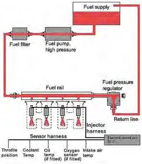
The modern electronic systems that cars are equipped with today utilize a number of sensors to monitor engine conditions. Sensors is basically can be defined as the tools that been used to obtain a data needed before being process and send them to the actuators. In this system, sensors are used to gain data such as quality of intake air, engine speed, engine temperature, idle to full load and intake air temperature. The data obtained than will be process by the Electronic Control Unit (ECU) before being send to the actuator which is fuel injection valves. The sensors that this system use is air flow sensor, engine speed sensor, throttle valve switch, engine temperature sensor and air temperature sensor.
6 pollution. Basically, based on Figure, fuel injection system normally two sub systems which are electronic system and fuel system. In electronic system, they have three components which are injectors, Electrical components unit(ECU), and sensors while in fuel system they have four components which are fuel pump, fuel filter, fuel pressure regulator and fuel rail.
Figure 2.2: Gasoline Fuel Injection System
With modern systems the injectors are usually opened individually in sequence (to match the engine firing order), this is known as sequential injection. The injectors are typically opened just prior to the inlet valve opening. All the required fuel is therefore delivered in one ‘opening’ of the injector. However, there are occasions where a very large quantity of fuel is required, for example during full load acceleration, where the injectors can be opened twice for every operating cycle (half the fuel quantity is delivered at each opening). Although it is possible to use a signal from the ignition system to trigger sequential injection, many systems use separate sensors to identify one of the cylinders, for example cylinder number, the ECU then uses this signal as a master reference and operates the injectors in sequence at the appropriate times. The sensor is referred to as a ‘cylinder identification sensor’ or ‘phase sensor’ which are usually either inductive or Hall effect sensors.
7 trigger lug attached to the camshaft could then cause an inductive sensor to provide a single reference signal. Alternatively, a Hall effect rotor attached to the camshaft could have a single ‘cut out’, thus producing a single reference pulse. A crankshaft speed/position sensor provides the necessary crankshaft angle and speed information. Some systems used a trigger signal provided by a sensor attached to a spark plug lead. The sensor generated a small electrical pulse that was used by the ECU as the master reference signal.
It is claimed that direct injection, when compared with an equivalent engine with port injection, provides a decrease in fuel consumption in the region of 15% to 20%, while engine power is slightly improved. One other benefit is that direct injection systems require very rapid vaporisation of the petrol to enable it to mix quickly with the air. This rapid
8
2.3 Fuel Injection Testing Equipment
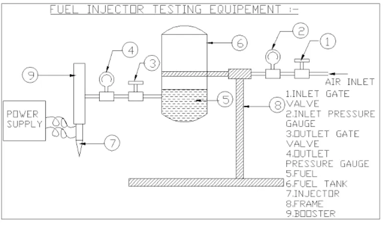
[image:22.595.117.504.306.533.2]With the introduction of GDI, Gasoline Direct Injection, over the last few years, there have been developed software & adaptors that allow for the servicing of these expensive to replace the problem injectors. One of them is fuel injection testing equipment. This equipment mainly functions as to test the injector in several test to know the condition of the injector(Cooper, 1981). The tests are pressure test, leak-off test and spray test. This machine contains some components that are same to the real fuel injection system in vehicle such as fuel pump, fuel rail and fuel tank. This machine will be drive by the programmable board which has been programmed to act like the Electronic Control Unit (ECU) to control the whole system of this machine(Lusignan, 1998).
Figure 2.3: Fuel injector Testing Equipment
Based on Figure 2.3, the compressed air is given to the input supply of this fuel injector
9
2.4 Components in Fuel Injection Testing Equipment
The fuel injection system in vehicle are designed to ensure the efficiency of fuel delivery and control the quantity of fuel that could not be achieved with previous system which is carburettor. Fuel Injection Testing Equipment resemble exactly what the injection system in vehicle so that the testing process could be done easily and correctly(Desai, Pawaskar and Manchekar, 2015).
2.4.1 Injector
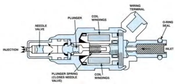
The injector is an electromechanical device that sprays fuel directly into combustion chamber, which is fed by a 12 volt supply from the ECM. The injector consists of a solenoid operated valve which is held in the closed position by a spring until the earth circuit is completed by the ECM. The injector normally consists of the nozzle, nozzle valve, spring and body as refer to Figure 2.4.1. When the electromagnetic field lifts the
[image:23.595.164.465.449.593.2]needle off its seat, fuel is delivered to the engine. The total lift on the needle is approximately 0.15 mm and has a reaction time around 1 millisecond.
10
2.4.2 Electronic Component Unit (ECU)
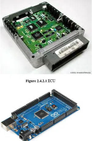
[image:24.595.165.466.259.719.2]An ECU contains a programmed memory, which, in an injection ECU, contains data on how much fuel should be injected under different operating conditions. In vehicle fuel injection system, when information is received from the sensors, the ECU refers to the programmed data and switches on the fuel injectors so that they deliver the required amount of petrol. Meanwhile, in this fuel injector testing machine, the ECU will be the programmable board that have been programmed earlier to act like ECU in vehicle fuel injection system. Below are the example of ECU and programmable board.
Figure 2.4.2.1:ECU