IMPROVE OF DESIGN AND ANALYSIS OF HYDRAULIC HOUSE FENCE OPENING USING TAP WATER PRESSURE
FAIZ ASWAD BIN AYOP AZMI
A report submitted
in fulfillment of the requirement for the degree of Bachelor of Mechanical Engineering (Design and Innovation)
Faculty of Mechanical Engineering
UNIVERSITI TEKNIKAL MALAYSIA MELAKA
ii
DECLARATION
I declare that this project report entitled “Improve of Design and Analysis of House Fence Opening” is the result of my own work except as cited in the references
Signature : ...
iii APPROVAL
I hereby declare that I have read this project report and in my opinion this report is sufficient in terms of scope and quality for the award of the degree of Bachelor of Mechanical Engineering (Design & Innovation).
Signature :. ...
iv
DEDICATION
v ABSTRACT
vi ABSTRAK
vii
ACKNOWLEDGEMENT
Alhamdulillah, appraises to Allah for His regards and bless, I able to accomplish my final year project. I am using this opportunity to express my gratitude to everyone that supported me throughout the course. I am thankful for my supervisor, Dr Mohd Basri Bin Ali, my second examiner, Dr Shafizal Bin Mat and my academic advisor, Mr. Mohd Nazim Bin Abdul Rahman for their aspiring guidance, invaluably constructive criticism and friendly advice during the thesis.
My deepest gratitude for my parents, Ayop Azmi Bin Abdul Rahman and Hamidah Binti Abdullah for supporting me in all aspects especially finishing my prototype. I also want to express my warm thanks to Faculty of Mechanical Engineering for giving enough information for finish this final year project.
viii CONTENT
CHAPTER CONTENT PAGE
DECLARATION ii
APPROVAL iii
DEDICATION iv
ABSTRACT v
ABSTRAK vi
ACKNOWLEDGEMENT vii
CONTENT viii
LIST OF FIGURES xi
LIST OF TABLES xiv
LIST OF ABBREVIATION xv
CHAPTER 1 INTRODUCTION 1
1.1 BACKGROUND 1
1.2 PROBLEM STATEMENT 3
1.3 OBJECTIVE 4
1.4 SCOPE OF PROJECT 4
CHAPTER 2 LITERATURE REVIEW 5
2.1 INTRODUCTION 5
2.2 TYPE OF FENCE 5
2.2.1 Swing fence 6
2.2.2 Slide fence 6
2.2.3 Vertical lift fence 7 2.2.4 Vertical pivot lift fence 8
2.2.5 Barrier arm fence 9
2.3 AUTOMATIC FENCE OPERATOR 9
2.4 AUTOMATIC FENCE COMPONENTS 11
2.4.1 Cylinders 11
2.4.2 Directional control valve 12 2.4.3 Pressure Relief valve 13 2.4.4 Digital remote control switch 14
ix
2.4.6 Hose 15
2.4.7 Valve 15
2.4.8 12V Battery 16
CHAPTER 3 METHODOLOGY 17
3.1 INTRODUCTION 17
3.2 RESEARCH METHOD 18
3.3 PROBLEM IDENTIFICATION 19
3.4 HOUSE OF QUALITY 19
3.5 PRODUCT DESIGN SPECIFICATION 19
3.6 CONCEPTUAL DESIGN 19
3.7 SIMULATE THE DESIGN 19
3.8 FABRICATION THE PRODUCT 20
3.8.1 Wiring 20
3.8.2 Cutting and connecting the hose 21
3.8.3 Drilling 22
3.8.4 Control valve 23
3.9 ANALYSE THE PERFORMANCE 23
3.9.1 Force analysis 24
3.9.2 Pressure 24
3.10 COMPARE BETWEEN PRODUCTS 25
CHAPTER 4 DATA AND RESULT 26
4.1 INTRODUCTION 26
4.2 HOUSE OF QUALITY 27
4.3 PRODUCT DESIGN SPECIFICATION 28
4.4 CONCEPTUAL DESIGN 29
4.4.1 Morphological chart 29
4.4.2 Concept 1 30
4.4.3 Concept 2 31
4.4.4 Concept 3 32
4.4.5 Concept 4 33
x
4.5 PUGH METHOD 35
4.6 SIMULATION OF SELECTED CONCEPT 36
4.7 FABRICATION PROCESS 39
4.8 WATER PRESSURE MONITORING 44
CHAPTER 5 DISCUSSION AND ANALYSIS 46
5.1 INTRODUCTION 46
5.2 PRODUCT TESTING 46
5.3 COMPONENT COST ANALYSIS 48
5.4 WATER CONSUMPTION 49
5.5 POWER CONSUMPTION 50
5.6 FORCE ANALYSIS 51
5.7 COMPARISON BETWEEN EXISTING PRODUCT
54
5.7.1 Product price comparison 54 5.7.2 Operating cost comparison 54 5.8 POTENTIAL OF COMMERCIALIZATION 55
CHAPTER 6 CONCLUSION AND RECOMMENDATION 56
xi
LIST OF FIGURES
Page
Figure 1.1: Swing automatic fence 2
Figure 1.2: Control valve 3
Figure 1.3: Location of control valve 4
Figure 2.1: Swing type fence 6
Figure 2.2: Cantilever slide type fence 7
Figure 2.3: Vertical lift fence 8
Figure 2.4: Vertical pivot lift fence 8
Figure 2.5: Barrier arm fence 9
Figure 2.6: Solar panel on operator 10
Figure 2.7: Mechanical fence operator components 10
Figure 2.8: Hydraulic cylinder 11
Figure 2.9: Double acting cylinder 11
Figure 2.10: Single acting cylinder 12
Figure 2.11: Directional control valve 12 Figure 2.12: Directional control valve with cylinder 13 Figure 2.13: Pressure relief valve components 13
Figure 2.14: Remote control switch 14
Figure 2.15: DC power supply 15
Figure 2.16: 6mm hose 15
Figure 2.17: Valve 16
Figure 2.18: 12V battery 16
Figure 3.1: Flow chart 18
Figure 3.2: FluidSIM process flow 20
Figure 3.3: Wire colour code 21
Figure 3.4: Wire connector 21
Figure 3.5: Cutter 22
Figure 3.6: T-joint 22
xii
Figure 3.8: Wall plug 23
Figure 3.9: Solenoid Valve 23
Figure 3.10: Pressure gauge 25
Figure 3.11: Connecting the pressure gauge 25
Figure 4.1: Concept 1 30
Figure 4.2: Concept 2 31
Figure 4.3: Concept 3 32
Figure 4.4: Concept 4 33
Figure 4.5: Concept 5 34
Figure 4.6: System at rest position 37
Figure 4.7: System extend operation 38
Figure 4.8: System retract position 38
Figure 4.9: Available components 39
Figure 4.10: New components 40
Figure 4.11: Manual of digital remote control 41
Figure 4.12: Wiring of socket 41
Figure 4.13: Valve circuit 41
Figure 4.14: Power adapter wiring 42
Figure 4.15: Power adapter to socket 42
Figure 4.16: Bracket installation 43
Figure 4.17: Cylinder wall mount 43
Figure 4.18: Cylinder installation 43
Figure 4.19: Pressure graph 45
Figure 5.1: Full assembly 46
Figure 5.2: Bracket problem 47
Figure 5.3: Bracket 47
Figure 5.4: Water consumption per usage 49
Figure 5.5: Swing type fence mass 52
Figure 5.6: Sliding type fence mass 53
xiii
xiv
LIST OF TABLES
Page
Table 4.1: House of Quality 27
Table 4.2: Morphological Chart 29
Table 4.3: Estimate price for main component concept 1 31 Table 4.4: Estimate price for main component concept 2 32 Table 4.5: Estimate price for main component concept 3 33 Table 4.6: Estimate price for main component concept 4 34 Table 4.7: Estimate price for main component concept 5 35
Table 4.8: Pugh method 36
Table 4.9: Available components list 39
Table 4.10: New components list 39
Table 4.11: Pressure daily monitoring 44
Table 5.1: Component cost 48
Table 5.2: Water consumption table 49
Table 5.3: Water tariff 49
Table 5.4: Push force 53
Table 5.5: Pull force 53
Table 5.6: Price comparison 54
xv
LIST OF ABBREVIATION
n.d. No date mm Millimeter
V Volt
m Meter
RM Ringgit Malaysia n/a Not available
kg Kilogram
1 CHAPTER 1
INTRODUCTION
1.1 BACKGROUND
Fence is one of design technology that help people to solve problem by adding barrier to cover the area needed. The main purpose of the fence is to protect and secure the place. Nowadays, the production of the fence does not only for security only, the fence need to have good aesthetic value, easy to operate and friendly user. In general, fence can be operating manually or automatically. For manual operating, it used men power to open and closed the door. It is not suitable for people that have pack schedule or need to rush for works. The automatic fence opening was invented to solve the problem and it also more safe to the user while opening the fence.
In 1974, the student in Toledo, Ohio was investing 100 dollars to build the companies of garage door and automatic gate system. This college student was most successful entrepreneurs when George Elbe make the advertisement on local newspaper, he wants to sell 13 automatic door openers. All the door had been sold and installed. According to the company philosophy, the company was focused on satisfaction and customer needs (D. Janbu,nd).
2
From the previous research, the source of power supply is from water pressure. The water supply is from Syarikat air Melaka berhad. The pressure and load of fence is related to each other because the pressure should be higher than the weight of the fence. The water pressure use to extend and retract the cylinder at the fence (M. Yusuf,2016)
Previous researcher emphasizing several important factors for using tap water in his project. The main factor is to increase safety awareness and improved the environmental protection by using the tap water. The water can reduce the pollution compared to hydraulic oil. The manufacturing cost also can be reduce because the manufacturer can replace the cost of hydraulic oil with tap water (M. Yusuf,2016).
In summary of previous researchers, they invented the most useful to assist the human work. The basic concept on the system is quite same but the component is different based on the design of the system. All the design have their own objective to produce the system to solve the problem.
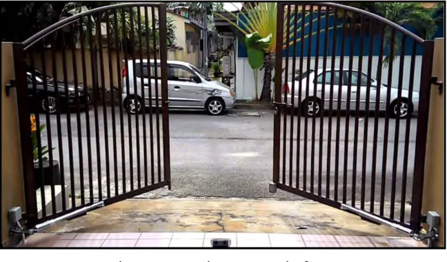
[image:17.595.143.467.483.673.2]This project was focused on producing the automatic fence that operates using water pressure source from water supply. The water supply is the low cost energy and it is usually having in all house in Malaysia. On literature review, the researcher was focused on device that can used for manufacturing the automatic system. The researcher also finds the information about the other automatic fence system and the type of fence in market.
3
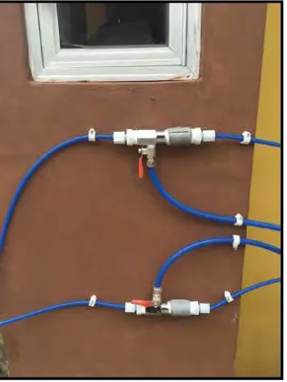
1.2 PROBLEM STATEMENT
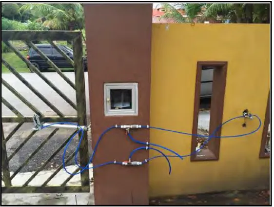
[image:18.595.228.386.339.549.2]The main problem of the existing product is the system does not used automatic system for opening and closed the fence. It need to closed and open the variety of valve to operate the fence. Each operation need to control two valve, which is one valve to control the release valve and another one valve to control the source of water as shown in Figure 1.2. It will increase the time to operate the fence and valve controller only can operate inside the house only as shown in Figure 1.3. The other problem with the existing fence is the cost. It is including the manufacturing cost and operating cost. The manufacturing cost is the cost when making the product including materials, labor and manufacturing overhead cost. The operating cost is including the source of power supply and it will be compare with electric and battery. To solve this problem, this project will improve the system by using automatic remote control to open and closed the fence.
4
Figure 1.3: Location of control valve (Source: M. Yusuf,2016)
1.3 OBJECTIVE
The objectives of this project are as follows:
1. To improve the design for existing hydraulic fence product. 2. To fabricate the prototype of the hydraulic house fence opening. 3. To analyze and compare the capability of the improvement product.
1.4 SCOPE OF PROJECT The scopes of this project are:
1. The improvement only included the swing type fence opening for terrace house. 2. Fabricate and install the new automatic system for fence opening.
5 CHAPTER 2
LITERATURE REVIEW
2.1 INTRODUCTION
The automatic fence is the popular technology that Malaysian peoples used for their home nowadays compared to manual fence. The main purpose of automatic fence is to assist human to open and close the fence for saving time and safety. The common automatic fence uses electrical system for control and generate power for movement. It is combine with mechanical system for moving the part, gear and linkage (M. Yusuf,2016).
In this project, the electrical system or battery as alternative energy source is only use for open and close the valve. The main energy is from pipe water pressure for moving the hydraulic system. The main purpose of this project is for improve the manual hydraulic system to automatic hydraulic system that using tap water. This project also to reduce the product cost and operating cost of automatic fence system.
2.2 TYPE OF FENCE
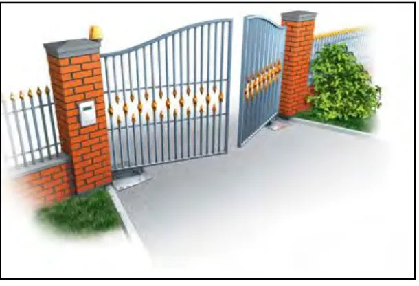
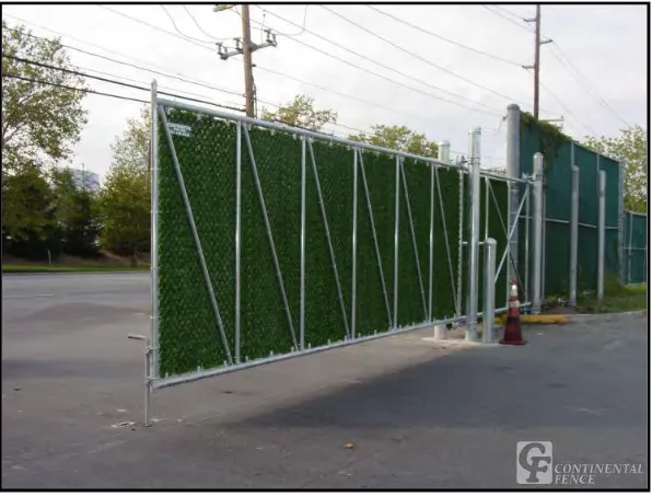
6 2.2.1 Swing fence
The swing fence is divide into two type which is single and double swing fence opening. This type of gate is common use for home because it is easy to install and the cost is less than other type of fence. The fence can open inwards or outwards (M. Hagaman,2013). When the automatic system attach to this type of fence, the fence usually can open in one direction, either inwards or outwards.
[image:21.595.153.458.348.556.2]Single swing gate usually 16 inch to 20 inch wide and it must have installed on a level flat plane for the fence driveway. The double swing gates can decrease the wide of the fence and it is having high aesthetic value compared to single swing fence (What are the Different Types of Driveway Gates,n.d.). The swing fence can hit the people or vehicle near the driveway when it is moving, so it need additional security system to prevent the it happen (M. Yusuf,2016).
Figure 2.1: Swing type fence (Source: Sivakumar. S,n.d) 2.2.2 Slide fence
7
[image:22.595.156.454.225.452.2]the opening of fence in order to save the space for installing the automatic gate system. The rear pipe track type is usually use with lower chain link fence. It also need 3 inch wider than the opening of fence for installation. For the cantilever type, it does not have any wheels on the ground. It can move on the driveway without care about the debris. The cantilever slide fence preferable especially in snow or ice area because the wheels is on the post of the fence (What are the Different Types of Driveway Gates,n.d.).
Figure 2.2: Cantilever slide type fence (Source: Security/Fences/Gates,n.d.) 2.2.3 Vertical lift fence
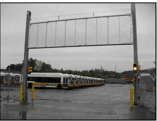
8
Figure 2.3: Vertical lift fence (Source: unknown,nd) 2.2.4 Vertical pivot lift fence
The vertical pivot lift fence is supported only by the operators of the fence and it does not require any support to hold the fence. It will rotate in and out to open or close the fence opening. The Figure show the fence in open position (M. Yusuf,2016).
Figure 2.4: Vertical pivot lift fence
(Source: Vertical Pivot Gates & Automatic Gate Operators,n.d.)
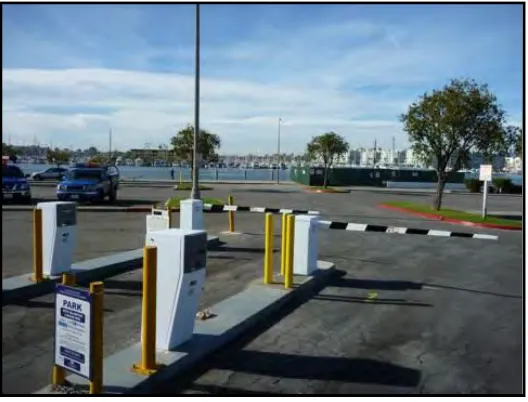
[image:23.595.174.473.437.637.2]9 2.2.5 Barrier arm fence
[image:24.595.191.455.235.436.2]In general, the barrier arm fence commonly used in parking lots and garages. It is also in a lot of commercial application including airports or public facilities. This fence can operate manually by using man power. It also can be operated automatically by using card reader, keypad or telephone entry system (Selling the best in Electric Driveway Gates,n.d.)). Figure 2.5 shows the barrier arm fence with card reader access.
Figure 2.5: Barrier arm fence (Source: Parking/Barrier Gates,n.d.)
The barrier arm fence is the efficient fence operator to reduce unwanted traffic due to the cost. This fence does not provide any security to secure the place (What are the Different Types of Driveway Gates,n.d.). The other type of fence should be considered to use if the place need high security