DESIGN AND ANALYSIS OF AN UNDERWATER PROPELLER BLADE
ZAIMA SYAFIQAH BINTI MUHAMMAD ZAILAN
A report submitted
in fulfilment of the requirement for the degree of Bachelor of Mechanical Engineering (with Honours)
Faculty of Mechanical Engineering
UNIVERSITI TEKNIKAL MALAYSIA MELAKA
DECLARATION
I declare that this project report entitled “Design and Analysis of an Underwater Propeller
Blade” is the result of my own except as cited in the references.
Signature : ……….
Name : Zaima Syafiqah Binti Muhammad Zailan
APPROVAL
I hereby declare that I have read this project report and in my opinion this report is sufficient
in terms of scope and quality for the award of the degree of Bachelor of Mechanical
Engineering.
Signature : ……….
Supervisor’s Name : Dr. Shamsul Anuar bin Shamsuddin
DEDICATION
To my beloved mother (Mariyani Binti Mohd Isa) and
i
ABSTRACT
ii ABSTRAK
iii
ACKNOWLEDGEMENT
First and foremost, all praise to Allah the Almighty, the Benevolent for His blessing and Guidance for giving me opportunity for learn and giving me strength to through the entire final year project 1 and 2. Many people contributed to the creation and completion on this final year project.
This project report is the sign that I have almost completed my study journey as Bachelor of Mechanical Engineering student in Universiti Teknikal Malaysia, Melaka. Therefore, I want to express my sincere appreciation to my Final Year Project supervisor, Dr Shamsul Anuar bin Shamsuddin, for the guidance, encouragement and positive feedback to help me whenever I need an advice and comment throughout the project . I am sincerely thanks to my second examiner and panels which are En.Masjuri Bin Musa @ Othman and Dr Shafizal Bin Mat for their guidance, advices and motivation along this final year project.
iv
TABLE OF CONTENT
PAGE DECLARATION
DEDICATION
ABSTRACT i
ABSTRAK ii
ACKNOWLEDGEMENTS iii
TABLE OF CONTENTS iv
LIST OF TABLES vi
LIST OF FIGURES vii
LIST OF APPENDICES x
LIST OF ABBREVIATIONS xi
LIST OF SYMBOLS xii
CHAPTER
1. INTRODUCTION 1
1.1 Background 1
1.2 Problem Statement 3
1.3 Objective 4
1.4 Scope of Project 4
2. LITERITURE REVIEW 5
2.1 Introduction 5
2.2 Design Analysis and Consideration 6
2.3 Parameter Analysis 6
2.3.1 Number of Blades 7
2.3.2 Propeller Diameter 7
2.3.3 Blade Design 8
2.3.4 Rake Angle 9
2.3.5 Ducted Propeller 10
2.4 CFD Model 12
2.4.1 Geometry and Propeller Domain 12
2.4.2 Grid Generation or Meshing 14
2.4.3 Setup and Solver 15
2.5 Propeller Theory 17
2.5.1 Actuator Disk Theory 17
2.5.1.1 Mathematical Modelling 19
2.6 Propeller Performance 21
3. METHODOLOGY 23
3.1 Steps of Methodology 23
3.2 Design Input Flow Chart 25
3.2.1 Preliminary Determination of Propeller Mathematical
Parameter 26
3.2.2 Morphological Chart 26
3.2.3 Conceptual Design 26
v
3.2.5 CFD Analysis of Flow Field 28
3.2.6 Calculation on Mathematical Modelling 28
3.3 Work Breakdown Structure 29
3.4 Gant Chart of the Project 30
4. RESULT AND DISCUSSION 33
4.1 Conceptual Design 33
4.1.1 Morphological Chart 33
4.1.2 Concept Generation 35
4.1.2.1 Concept 1 35
4.1.2.2 Concept 2 36
4.1.2.3 Concept 3 37
4.1.3 Concept Evaluation 38
4.2 Geometry Design 41
4.3 Computational Fluid Dynamics Analysis 42
4.3.1 Geometry Design with Propeller Domain 42
4.3.2 Grid Generation or Meshing 43
4.3.3 Setup and Solver 44
4.4.4 Results 45
4.4 Mathematical Modelling Calculation 51
4.4.1 Tabulated Data 51
4.4.2 Example Calculation 52
4.4.3 Graph Plotting 53
5. CONCLUSION AND RECOMMENDATIONS
FOR FUTURE RESEARCH
56
5.1 Conclusion 56
5.2 Recommendation 57
REFERENCES 58
vi
LIST OF TABLES
TABLE TITLE PAGE
2.3.5 Comparison of different area design propeller 11
2.4.1 Main Geometry of the Propeller 13
2.4.3.1 Parameter of ducted propeller designed 16
2.4.3.2 Variation speed, thrust and torque of the propeller blade 17
2.6.1 Propeller Geometry Specification 20
2.6.2 Computational estimation of Thrust and Torque 21
4.1.3(a) Evaluation Scheme for the Design 39
4.1.3(b) Concept Alternatives of the Design 40
4.3.3 The Value of Various RPM of the Rotating Region 45
4.3.4.1 Solver Result Data for Low RPM Value 46
4.3.4.3 Solver Result Data for Medium RPM Value 47
4.3.4.5 Solver Result Data for High RPM Value 49
4.4.1 Important data from CFD simulation analysis in different RPM
value
51
vii
LIST OF FIGURES
FIGURE TITLE PAGE
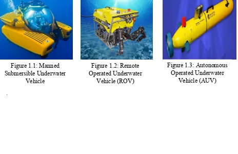
1.1 Manned Submersible Underwater Vehicle 2
1.2 Remote Operated Underwater Vehicle (ROV) 2
1.3 Autonomous Operated Underwater Vehicle (AUV) 2
2.1.1 Typical Propeller Drawing 6
2.3.3 (a) Parent Propeller 8
2.3.3 (b) Design Propeller (7% decreased) 8
2.3.3 (c) Design Propeller ( 14% decreased) 9
2.3.4 (a) 0 degree rake angle 10
2.3.4 (b) 15 degree rake angle 10
2.3.4 (c) 30 degree rake angle 10
2.3.5 Profiles of duct type 19A and 19Am 11
2.4.1(a) Domain of the Free Propeller Model 12
2.4.1(b) Computational domain for the propeller blade 13
2.4.2(a) Grid of the propeller 15
2.4.2(b) Grid over the entire domain 15
2.4.3.2 3D design for ducted propeller 16
viii
2.6.3 Propeller with four blade efficiency map 21
2.6.4 Plotted graph efficiency of propeller against propeller diameter
with various RPM
22
3.1 Step of Methodology 23
3.2 Methodology Flow of Blade Design 25
3.2.4 Specification dimension for T200 thruster 27
3.3 Work Breakdown Structure of “ Design and Analysis of
Underwater Propeller Blade“
29
3.4 Gant Chart of Final Year Project 1 30
3.5 Gant Chart of Final Year Project 2 31
4.1.1 Morphological Chart of Propeller Design 33
4.1.2(a) First Conceptual Design 35
4.1.2(b) Second Conceptual Design 36
4.1.2(c) Third Conceptual Design 37
4.1.3 Mind Maps of Important Design Factors that Effecting Propeller
Efficiency
38
4.2.1(a) Top view 41
4.2.1(b) Side view 41
4.2.1(c) Front view 41
4.2.1(d) Isometric view 41
4.3.1(a) The details view of the enclosure 1 (first propeller domain) 42
4.3.1(b) The details view of the enclosure 2 (second propeller domain) 42
4.3.1 (c) The view of the propeller blade with enclosures 43
4.3.2(a) Meshing of propeller blade with both first and second propeller
domains.
ix
4.3.2(b) Meshing of propeller blade with first propeller domain 43
4.3.2 The details view meshing 44
4.3.4.1 Solver Result for 31.42 rad/s of propeller blade in CFD 45
4.3.4.2 Velocity Distribution for Low RPM Value of Propeller Blade in
CFD
46
4.3.4.3 Solver Result for 183.25 rad/s of Propeller Blade in CFD 47
4.3.4.4 Velocity Distribution for Medium RPM Value of Propeller Blade
in CFD
48
4.3.4.5 Solver Result for 397.94 rad/s of Propeller Blade in CFD. 49
4.3.4.6 Velocity Distribution for High RPM Value of Propeller Blade in
CFD
50
4.4.3 (a) Graph of Efficiency of the Propeller (%) against RPM (rad/s) 53
4.4.1 (b) Graph of Efficiency of the Propeller (%) against CT (Thrust
Coefficient)
54
4.4.3(c) Graph of Efficiency of the Propeller (%) against Velocity Inlet 54
x
LIST OF APPENDICES
APPENDIX TITLE PAGE
A Details Drawing of Ducted Propeller Blade 63
B Details Drawing of Unducted Propeller Blade 64
C First Conceptual Design Choice with Surface
Area Value
65
D Second Conceptual Design Choice with Surface
Area Value
65
E Third Conceptual Design Choice with Surface
Area Value
66
F Calculation of Mathematical Modelling in Excel 66
G Specification Details of T200 Thruster by Blue
Robotics
xi
LIST OF ABBREVIATIONS
ROV - Remote Operated Underwater Vehicle
AUV - Autonomous Underwater Vehicle
CFD - Computational Fluid Dynamics
BEM - Boundary Element Method
BAR - Blade Area Ratio
2D - Two Dimension
xii
LIST OF SYMBOLS
D, d - Diameter
R, r - Radius
𝑚̇ - Mass Flow Rate
T - Thrust of the Propeller
Q - Torque Produced by the Propeller
Ao - Surface Area of the Propeller Blade
VA - Inlet velocity
VB - Velocity against the Thrust of the Propeller
VC - Outlet velocity
n - Rotational Speed
PD - Power obtained by the propeller
J - Advance Ratio
CT - Thrust Coefficient
CQ - Torque Coefficient
ρ - Density of the Water
1 CHAPTER 1
INTRODUCTION
1.1 Background
Nowadays, scientists always find the best solution to get themselves or their
instruments into a very specific parts in order to understand the ocean. They have to develop
the underwater vehicle to make the research in an easy way. Traditionally, the researchers need
to use ships to take a photo of the depths and to collect samples of water, rock, and marine life.
However, in modern life, they do some innovation such as remote-controlled vehicles,
autonomous, and towed robots.
Underwater vehicles are classified as either Manned, Remotely Operated Underwater
Vehicles (ROV) and Autonomous Underwater Vehicle (AUV). They are submersible vehicle
that can be assigned to do certain task underwater. The underwater vehicle also provides the
functions necessary to serve as undersea tools for science and industry.
Manned submersibles are underwater vehicles that are controlled by human operators.
These allow scientists to dive into the deep ocean and collect data or make observations first
hand.
A remotely-operated underwater vehicle (ROV) is safe and controlled by an operator
who remains out of the water which is this robot was controlled by a person on the surface. An
2
However, different with autonomously-operated underwater vehicle (AUV) which is
designed to work without an operator and without a direct connection to the surface. These
AUV are normally designed for a particular application and are pre-programmed to operate
definite particular tasks. Figure 1.1, 1.2 and 1.3 show the example design of the manned
submersible, Remote Operated Underwater Vehicle (ROV) and autonomous operated
underwater vehicle (AUV) respectively.
All these underwater vehicles need a propulsion from the thruster to move themself.
The design of the propeller blade inside the thruster is very important to ensure the underwater
vehicle would able to move in efficient way. S. O. Oladokun (2015) believes that the propeller
blade would able to move the ship against resistant of water which is this propeller converts
engine torque into propulsive force or thrust and produce forward motion. In propeller design,
it is important to ensure that it drives the vessel efficiently.
.
Figure 1.1: Manned Submersible Underwater
Vehicle
Figure 1.2: Remote Operated Underwater
[image:18.595.60.524.467.767.2]Vehicle (ROV)
Figure 1.3: Autonomous Operated Underwater
3 1.2 Problem Statement
Lately, the ROV evolution has focussed on smaller size and higher efficient energy
technology. The propeller blade of ROV is very important in producing a more efficient
horizontal and vertical manoeuvre. However, the number of research on designing and
manufacturing marine propeller is less. Most of them depend on the propeller of the airplane
for propulsion as off the shelf propeller is more sensible because it is cheaper and easy to
replace. Yet the use of airplane propeller in marine vehicle is not suitable because the density
of air is 1000 times less than water (D’Epagnier, 2006).
The thruster and propeller blade itself have an electric motor that attached to it which it
gives the underwater robot as a propulsion device. These enable the robot to make a movement
and have the ability to against sea water resistance. If the efficiency of the propeller blade is
low, the underwater vehicle would not able to move faster in an efficient way. Plus, underwater
vehicle will have a low ability to against the sea water resistance (Maghareh, 2017)
Therefore, it is important for this research to clearly show the steps of the advance
method in ROV propeller development which will promote engineers to adapt and continue
the new design. The research of the propeller is important in order to know the best design
based on the previous lesson. So, based on the research and process learning, the improvement
of the propeller blade can be made referring to the standard criteria and parameter
4 1.3 Objective
The goals of this final year project are as follows:
1. To determine the important design factors that affect propeller efficiency.
2. To identify the velocity and total thrust of propeller blade in order to determine the
ROV propeller blade efficiency.
1.4 SCOPE OF PROJECT
This research focuses on the hydrodynamic performance of the ROV where an efficient
propeller is needed to be found using the designing and stimulating of the propeller blade in
order to produce a reliable propulsion system.
The scopes of the study on ROVs propeller blade are:
i. To study the design process of ROVs propellers
ii. To design and modelling a propeller blade for ROVs referring to design parameters.
iii. To analyse the velocity and total thrust of the propeller blade using Computational Fluid
Dynamics (CFD)
5 CHAPTER 2
LITERITURE REVIEW
2.1 Introduction
Most of the literature review on propeller blade is full with experimental and analytical
data that related with performance information and the design criteria. A propeller turns the
engine power into the operating force of the ship and usually the propellers are used as
propulsions and used to progress significant dive to propel the vehicle at its operational speed
and RPM (B. Harish et al. 2015). I. Anthony et al. (2013) state that the propeller is a type of a
fan that transmits power by converting rotational motion into thrust.
Propeller dynamics can be represented by both Bernoulli’s principle and Newton’s third
law. A propeller is sometimes known as screw which it is actually can have a single blade, but
in practice there always more than one in order to make the forces involved is balanced
(Anthony et al. 2013). These authors have explored their study about the propeller blade
efficiency and knowing that a propeller with blade area ratio of 0.55 has the open water
efficiency about 73%.
Usual propeller blade geometry is shown in Fig.2.1.1 which profiles some of the terms
used in designing an underwater propeller system. The propeller type, geometrical and
performance parameters like radial velocity, thrust coefficient and others impressed the ship
6
Figure 2.1.1: Typical propeller drawing (Anthony et al. 2013)
2.2 Design Analysis and Considerations
Anthony et al. (2013) focused the propeller design analysis at obtaining least power
requirements, cavitation, noise, vibration and supreme efficiency conditions at a sufficient
revolution. Ekinci (2011) believed that there are two methods are commonly used in propeller
design which are by using the diagrams obtained from open water propeller experiments for
systematic propeller series and mathematical methods (lifting line, lifting surface,
vortex-lattice, BEM (boundary element method) based on circulation theory.
2.3 Parameter Analysis
Propeller diameter, number of blades and propeller speed is the parameters that supply
7
will result in different efficiencies. Therefore, D’Epagnier et al. (2007) make a further study of
the parameter that is important to know the propeller optimization.
2.3.1 Number of blades
Mutalib et al. (2015) mention that the most frequent marine propellers are designed to
decrease the noise sound such as three or four bladed marine propellers. The number of blades
selected will impact the level of unsteady forces working on them. Optimum open
water potency will increase with increase within the range of blades by considering the
efficiency of propeller blade.
2.3.2 Propeller diameter
Matt (2015) claims that the selected propeller diameter and pitch is important where it
contribute in the propeller’s ability to absorb power, the engine’s ability to produce power, and
either it properly matched at the engine’s rated rpm.
These author also state that the huge diameter and a shallow pitch of propeller blade
may be used, or a smaller diameter and a steeper pitch, to produce the equal load on the engine.
However, if it going so much in either method through, the efficiency of the propeller will be
decrease.
In a terrible tiny diameter, steep pitch propeller tends to place a lot of work into spinning
the water flow, and fewer into accelerating fast away from the boat. Besides that, even in fixed
rpm, if the diameter is increase too much, the pitch should be created terribly shallow,
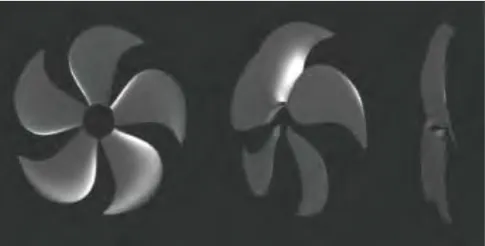
8 2.3.3 Blade area and blade design
Blade area ratio (BAR) is the magnitude relation or ratio of the whole area of the blades,
divided by the whole area of the propeller. This blade area ratio might affect the propeller
efficiency and thrust making performance. Blade design may become the minor consideration
in selecting the propeller design. However, the blade area ratio may effected by the blade
design. Therefore, the different blade design may affect the efficiency of the propeller blade
itself.Lee et al. (2010) had design technique for greater performance of the marine propellers
with an optimum propeller performance. These authors was adjusting expanded areas of the
propeller blade. Results show that efficiency can be grow up to over 2% by decreased the blade
area. Table 2.3.3 shows the comparison result for parent propeller, design propeller (7%
[image:24.595.174.426.376.503.2] [image:24.595.177.420.535.658.2]decreased) and design propeller (14% decreased).
Figure 2.3.3 (a) Parent propeller (Lee et al. 2010)