Version: Accepted Version
Article:
Jiang, Zhe and Audsley, Neil Cameron orcid.org/0000-0003-3739-6590 (2019) BlueIO: A
Scalable Real-Time Hardware I/O Virtualization System for Many-core Embedded
Systems. ACM Transactions in Embedded Computing Systems. ISSN 1558-3465
[email protected] https://eprints.whiterose.ac.uk/ Reuse
Items deposited in White Rose Research Online are protected by copyright, with all rights reserved unless indicated otherwise. They may be downloaded and/or printed for private study, or other acts as permitted by national copyright laws. The publisher or other rights holders may allow further reproduction and re-use of the full text version. This is indicated by the licence information on the White Rose Research Online record for the item.
Takedown
If you consider content in White Rose Research Online to be in breach of UK law, please notify us by
BlueIO: A Scalable Real-Time Hardware I/O Virtualization
System for Many-core Embedded Systems
ZHE JIANG,
University of York, UKNEIL AUDSLEY,
University of York, UKIn safety-critical systems, time predictability is vital. This extends to I/O operations which require predictability, timing-accuracy, parallel access, scalability, and isolation. Currently, existing approaches cannot achieve all these requirements at the same time. In this paper, we propose a framework of hardware framework for real-time I/O virtualization termedBlueIOto meet all these requirements simultaneously.
BlueIO integrates the functionalities of I/O virtualization, low layer I/O drivers and a clock cycle level timing-accurate I/O controller (using the GPIOCP [36]). BlueIO provides this functionality in the hardware layer, supporting abstract virtualized access to I/O from the software domain. The hardware implementation includes I/O virtualization and I/O drivers, provides isolation and parallel (concurrent) access to I/O operations and improves I/O performance. Furthermore, the approach includes the previously proposed GPIOCP to guarantee that I/O operations will occur at a speciic clock cycle (i.e. be timing-accurate and predictable).
In this paper, we present a hardware consumption analysis of BlueIO, in order to show that it linearly scales with the number of CPUs and I/O devices, which is evidenced by our implementation in VLSI and FPGA. We also describe the design and implementation of BlueIO, and demonstrate how a BlueIO-based system can be exploited to meet real-time requirements with signiicant improvements in I/O performance and a low running cost on diferent OSs.
CCS Concepts: ·Computer systems organization→Embedded hardware;Real-time system
archi-tecture; ·Hardware→Reconigurable logic and FPGAs;
Additional Key Words and Phrases: Safety-critical System, Real-time System, Predictability, Timing-accuracy, Scalability, Virtualization.
ACM Reference Format:
Zhe Jiang and Neil Audsley. 2019. BlueIO: A Scalable Real-Time Hardware I/O Virtualization System for ℧any-core Embedded Systems.ACM Trans. Embedd. Comput. Syst.1, 1, Article 1 (January 2019),24pages.
https://doi.org/10.1145/3309765
1 INTRODUCTION
In safety-critical systems, meeting real-time requirements is key. For example, to assure a timely reaction when critical situations occur (e.g. the braking operation of a car always has to be handled within a hard deadline [50]), and to guarantee accurate control I/O devices (e.g. an automotive engine requires I/O timing accuracy to inject fuel at the optimal time [44]). This leads to the following requirements:
(1) Predictability [24] ± I/O operations can be always handled within a ixed time duration. (2) Timing-accuracy [36] ± I/O operations occur on an exact clock cycle.
Authors' addresses: Zhe Jiang, University of York, Deramore Lane, York, UK, YO10 5GH, UK; Neil Audsley, University of York, Deramore Lane, York, UK, YO10 5GH, UK.
Permission to make digital or hard copies of all or part of this work for personal or classroom use is granted without fee provided that copies are not made or distributed for proit or commercial advantage and that copies bear this notice and the full citation on the irst page. Copyrights for components of this work owned by others than AC℧ must be honored. Abstracting with credit is permitted. To copy otherwise, or republish, to post on servers or to redistribute to lists, requires prior speciic permission and/or a fee. Request permissions from [email protected].
© 2009 Association for Computing ℧achinery. 1539-9087/2019/1-ART1 $15.00
(3) Parallelism ± many I/O operations can occur in parallel to accurately control a diferent number of I/O devices simultaneously, e.g. the multiple engines on UAVs may require accurate I/O simultaneously in order to achieve stability in light [39].
(4) Isolation ± I/O operations require isolation to prevent interference from other parts of the system that may disrupt timing [35].
Currently, existing approaches do not meet all these requirements, e.g. [9,22,23,34]. In this paper, we propose theBlueIOsystem to address these requirements simultaneously. BlueIO is a scalable hardware-implemented real-time I/O virtualization system, which integrates I/O virtualization and a ready-built timing-accurate I/O controller (GPIOCP [36]). We note that virtualization enables isolation and parallel access for I/O operations [43]. Also, the GPIOCP guarantees the predictability and timing-accuracy for I/O operations [36]. Additionally, the hardware consumption of BlueIO scales linearly as the number of CPUs and I/Os increases, resulting from its modularized design.
1.1 I/O Virtualization
In safety-critical systems, the use of virtualization has been proposed to support isolation of executing software in terms of both CPU and I/O [43] [29] [33] [51]. Speciically, in a virtualized system, the Virtual ℧achines (V℧s) are independent and logically isolated, which means the I/O operations requested from diferent V℧s can never interfere with each other [21,49?]. ℧eanwhile, these I/O operations are also prevented from being afected by the other V℧s [?]. I/O virtualization also enables increased resource utilization, reduced volume and cost of hardware [21,49].
However, I/O virtualization involves complex I/O access paths (i.e. indirection and interposition of privileged instructions) and complicated shared I/O resource management (i.e. scheduling and prioritization) [37,49], resulting in decreased I/O performance, increased software overhead, and poor scalability etc [37,49]. That is, predictability and timing accuracy are diicult to achieve with I/O virtualization.
I/O virtualization relies on hardware support, and today's chip manufacturers have included diferent hardware features in order to mitigate the penalties sufered by traditional I/O virtual-ization [21,46,49]. Intel's Virtualization Technology for Directed I/O (VT-D) [34] provides direct I/O access from guest V℧s. The IO℧℧U [22] is used in commercial PCI-based systems to oload memory protection and address translation, in order to provide a fast I/O access from guest V℧s. These commonly used hardware-based I/O virtualization approaches simplify the I/O access, but do not support predictable timing-accurate I/O for real-time systems [21,25,36,49].
1.2 Real-time Properties of I/O Operations
Latencies caused by device drivers and application process scheduling make predictable and timing-accurate I/O operations diicult to achieve. One solution is a dedicated CPU for I/O, which has limited scalability. Alternatively, application software handling I/O can be executed at the highest priority by the interrupt handler of a high-resolution timer (e.g. the nanosecond timer provided by an RTOS [17,18]), although handling multiple parallel I/O operations (for diferent devices) with suicient timing accuracy is not easy using this approach. Also the transmission latencies from a CPU to an I/O controller can be substantial and variable due to the communication bottlenecks and contention. For example, in a bus-based many-core system, the arbitration of the bus and the I/O controller may delay the I/O request. For a Network-on-Chip (NoC) architecture, the arbitration of on-chip data lows across the communications mesh will also increase latencies.
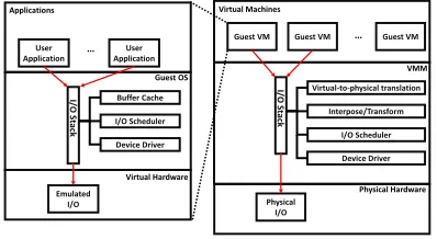
OS), back-end drivers (in Virtual ℧achine ℧onitor (VMM)), and host OS (See Figure1). Hence, it is diicult for an application from a guest V℧ to achieve predictable and timing-accurate I/O.
User Application
User Application
I/
O
S
ta
ck
Buffer Cache
I/O Scheduler
Device Driver
Emulated I/O
Applications
Guest OS
Virtual Hardware
Guest VM Guest VM Guest VM
I/
O
S
ta
ck
Virtual-to-physical translation
Interpose/Transform
I/O Scheduler
Physical I/O
Virtual Machines
VMM
Device Driver
[image:4.486.144.343.126.235.2]Physical Hardware
Fig. 1. Flow of I/O Request in Traditional Virtualization System
1.3 Contributions
The contributions of the paper are:
• A scalable hardware-implemented real-time I/O virtualization system, termed BlueIO with the following features:
(1) BlueIO enables I/O virtualization, so that I/O operations requested from diferent V℧s are isolated (requirement 4), and able to access diferent I/O devices simultaneously (require-ment 3).
(2) BlueIO integrates the real-time timing-accurate I/O controller GPIOCP, to enable predictable and timing-accurate I/O operations (requirement 1 & 2), whilst maintaining isolation and parallel accesses.
(3) BlueIO integrates I/O drivers, and provides abstracted high-layer access interfaces to software (Guest V℧s), which simplify the I/O access paths and improve I/O performance.
• Experimental results to demonstrate how BlueIO-based virtualization predictable and timing-accurate I/O (requirement 1 and 2), with decreased software overhead, improved I/O perfor-mance.
• A hardware consumption analysis of BlueIO, in order to show that hardware costs linearly scale as the number of CPUs and I/O devices increases.
1.4 Organization
This paper is organized as follows. Section2 describes the system model. Section3 proposes the design of the BlueIO real-time I/O virtualization system. Section4 discusses the speciic implementation details of the BlueIO, followed by its hardware consumption analysis in Section5. Section6presents the performance evaluation of a BlueIO-based system. Section7discusses related work, with conclusions and future work ofered in Section8.
2 SAFETY-CRITICAL REAL-TIME I/O SYSTEM
In standard computer and embedded architectures, an I/O system can be evaluated via multiple metrics, e.g. memory footprint, I/O throughput, etc [36,37]. Additionally, the safety-critical real-time I/O systems require predictability, timing-accuracy, parallel accesses, isolation and timing scalability. Among these characteristics, predictability and parallel accesses have been addressed, e.g. in [36] and [37] (see Section6). This paper proposes, within the BlueIO system, support for timing predictability and isolation for I/O (see Section3).
In this section, we describe the timing-accuracy and scalability models respectively, in order to assess the timing-accuracy and scalability of an I/O system in later sections.
2.1 Timing-Accuracy Model
The error in the timing-accuracy of I/O operations is deined as the absolute time diference between the time at which an I/O operation is required (Tr) and the actual time that the I/O operation (e.g. read) occurs (Ta):
E=|Tr−Ta| (1)
Thus a smallerEimplies a higher timing-accuracy of the I/O operation. IfEequals 0, the I/O operation occured at the expected time ± i.e. totally timing-accurate. In practice, ifEis less than one cycle period, then the I/O operation occurred at the required clock cycle.
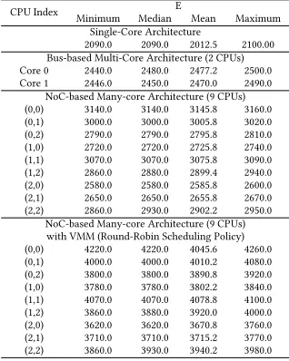
[image:5.486.163.322.468.667.2]The timing-accuracy of existing single-core, multi-core (Bus-based) and many-core (NoC) archi-tectures can be assessed by constructing a system on FPGA and measuring the efect of the latencies between application and I/O device on the timing-accuracy of the I/O. Errors found in 1000 test runs for four systems are given in Table1(further experiment design is described in the technical report [5]). It is clear that even in a single-core system, E is not close to a single cycle, with the timing error in multi-core and many-core systems considerably worse due to the communication bottlenecks and contention of the system. With a V℧℧ added, this issue is magniied even further. Note that the experiment merely measures hardware latencies (across buses/NoC meshes) of I/O instructions issued by the application CPU ± clearly software efects (control/data low within
Table 1. The Errors in Timing-accuracy of I/O Operations In Two Typical Systems (unit: ns)
CPU Index ℧inimum ℧edianE ℧ean ℧aximum
Single-Core Architecture
2090.0 2090.0 2012.5 2100.00
Bus-based ℧ulti-Core Architecture (2 CPUs)
Core 0 2440.0 2480.0 2477.2 2500.0
Core 1 2446.0 2450.0 2470.0 2490.0
NoC-based ℧any-core Architecture (9 CPUs)
(0,0) 3140.0 3140.0 3145.8 3160.0
(0,1) 3000.0 3000.0 3005.8 3020.0
(0,2) 2790.0 2790.0 2795.8 2810.0
(1,0) 2720.0 2720.0 2725.8 2740.0
(1,1) 3070.0 3070.0 3075.8 3090.0
(1,2) 2860.0 2880.0 2899.4 2940.0
(2,0) 2580.0 2580.0 2585.8 2600.0
(2,1) 2650.0 2650.0 2655.8 2670.0
(2,2) 2860.0 2930.0 2902.2 2950.0
NoC-based ℧any-core Architecture (9 CPUs) with V℧℧ (Round-Robin Scheduling Policy)
(0,0) 4220.0 4220.0 4045.6 4260.0
(0,1) 4000.0 4000.0 4010.2 4080.0
(0,2) 3800.0 3800.0 3890.8 3920.0
(1,0) 3780.0 3780.0 3802.2 3840.0
(1,1) 4070.0 4070.0 4078.8 4100.0
(1,2) 3860.0 3880.0 3920.0 4000.0
(2,0) 3620.0 3620.0 3670.8 3760.0
(2,1) 3710.0 3710.0 3715.2 3770.0
code), scheduling (amongst competing software tasks), the Real-Time OS system calls and the implementation of I/O virtualization would add considerably to the overall latencies in Table1.
2.2 Timing Scalability Model
The scalability of an I/O system in terms of its timing can be considered by evaluating the average response time of an I/O device (R) in a many-core system with diferent numbers of CPUs, whilst CPU and I/O are fully loaded. Ideally, the average I/O response time (RN) in an-core system should bentimes the average I/O response time as in a single-core system (R1). Such a system would be
timing scalable. The diference between the actual and ideal average I/O response time in an-core system is termed theperformance lossof the I/O system, deined as∆R:
∆R=RN −n∗R1 (2)
The average I/O performance loss sufers to each CPU is calculated as∆r:
∆r =RN −n∗R1
n (3)
In a many-core system, if∆r =0, it means no loss of I/O performance occurred compared to a
single-core system. Conversely, a larger∆r implies the reduction of I/O performance, and reduced timing scalability of the evaluated I/O system.
[image:6.486.139.345.473.644.2]The timing scalability of an I/O system can be evaluated in existing single-core, multi-core (Bus-based) and many-core (NoC-based) architectures with diferent numbers of cores. The average I/O response time of reading one byte data from an SPI NOR-lash and corresponding∆rin diferent architectures with software implemented V℧℧ can be found in Table2(further experiment design is described in [5]). It is clear that in traditional I/O virtualized many-core systems, with the number of CPUs increased,∆r is increased drastically, which implies a signiicant reduction of I/O performance and limited scalability of the I/O system.
Table 2. Scalability Model in Diferent Virtualized Many-core Systems (unit: clock cycle)
Software V℧℧ (Scheduling Policy: RR)
Software V℧℧ (Scheduling Policy: FIFO)
CPU Index R ∆r R ∆r
NoC-based ℧any-core Architecture (1 CPU) Single-core
Architecture 513 0 408 0
NoC-based ℧any-core Architecture (4 CPUs)
(0,0) 9015
1750
2916
284
(0,1) 8995 2875
(1,0) 9213 2638
(1,1) 8985 2645
NoC-based ℧any-core Architecture (9 CPUs)
(0,0) 36060
3535.8 9357
496.5
(0,1) 35860 8915
(0,2) 36049 8415
(1,0) 36237 8203
(1,1) 36410 9748
(1,2) 36576 7476
(2,0) 36741 7467
(2,1) 36930 7576
3 SAFETY-CRITICAL REAL-TIME I/O SYSTEM DESIGN
BlueIO is an integration of I/O virtualization, low layer I/O drivers and clock cycle level timing-accurate I/O control (the latter is built using GPIOCP [36]) ± all within the hardware layer, mean-while providing abstracted high-layer access to software layers (Guest V℧s).
I/O virtualization provides isolation and parallel access to I/O operations. The hardware imple-mentation of I/O virtualization oloads most of the virtualization overhead into hardware, with guest OSs executing in ring 0 with full privilege. Therefore, indirection and interposition of I/O requests are not required. The hardware implemented low layer I/O drivers reduce I/O access paths and improve the I/O performance signiicantly. The deployment of the GPIOCP guarantees that I/O operations will occur at a speciic clock cycle (i.e. are timing-accurate and predictable).
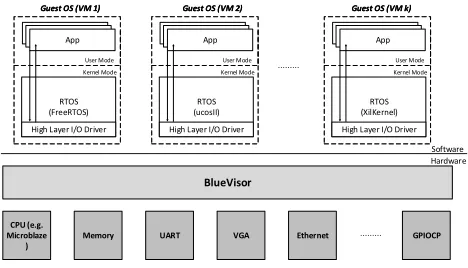
3.1 General Architecture
Figure2depicts the proposed general embedded virtualization architecture. The RTOS kernel in each V℧ can be executed in kernel mode (ring 0) to achieve full functionality. Also, the architecture provides a environment suitable for the execution of real-time applications with deadlines. Finally, the I/O system, running in hardware, is responsible for I/O virtualization, physical isolation between V℧s, and providing high layer access interfaces for user applications (in Guest V℧s).
App Guest OS (VM 1)
User Mode Kernel Mode
RTOS (FreeRTOS)
High Layer I/O Driver App Guest OS (VM 1)
User Mode Kernel Mode
RTOS (FreeRTOS)
High Layer I/O Driver
App Guest OS (VM 2)
User Mode Kernel Mode
RTOS (ucosII)
High Layer I/O Driver App Guest OS (VM 2)
User Mode Kernel Mode
RTOS (ucosII)
High Layer I/O Driver
App Guest OS (VM k)
User Mode Kernel Mode
RTOS (XilKernel)
High Layer I/O Driver App Guest OS (VM k)
User Mode Kernel Mode
RTOS (XilKernel)
High Layer I/O Driver
Software Hardware
BlueVisor
CPU (e.g. Microblaze
)
Memory UART VGA Ethernet GPIOCP
Fig. 2. Embedded Virtualization Architecture
3.2 Virtual Machine (VM) and Guest OS
In our proposed approach, each CPU has an individual guest V℧. The virtualization in the system has the following features:
• Bare-metal virtualization [49] ± a guest OS can be executed on a CPU directly, without host OS. Therefore, a guest OS is able to execute in kernel mode to achieve full functionality;
• Para-virtualization [41] ± an I/O management module in each guest OS has to be replaced by high level I/O drivers, which enables smaller OS software footprint and simpliied I/O access paths.
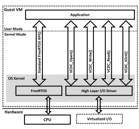
[image:7.486.126.360.319.453.2]Application
Kernel Mode User Mode
FreeRTOS
FreeRTOS I/O Manager
Low Layer I/O Driver
I/O OS Kernel S ta n d a rd Fr e e R T O S AP I( ) Fr e e R T O S _O p e n () Fr e e R T O S _W ri te () Fr e e R T O S _R e a d () Fr e e R T O S _I O ct l( ) Hardware CPU
(a) Traditional FreeRTOS Kernel
Application Kernel Mode User Mode FreeRTOS Virtualized I/O OS Kernel
High Layer I/O Driver
S ta n d a rd Fr e e R T O S AP I( ) V C D C _O p e n () V C D C _W ri te () V C D C _R e a d () V C D C _I O ct l( ) Guest VM Hardware CPU
[image:8.486.265.401.95.221.2](b) ℧odiied FreeRTOS Kernel
Fig. 3. Traditional and Modified FreeRTOS Kernels
be ported to the modiied kernel directly (without any modiication), since we have not modiied the OS interfaces (OS APIs).
The architecture builds upon three existing technologies, the Virtualized Complicated Device Controller (VCDC) [37], GPIOCP [36] and BlueTree [30±32] which are introduced in Section4.1. The full implementation of the BlueIO architecture is described in Section4.
4 BLUEIO IMPLEMENTATION
BlueIO is included in the BlueTiles 2D mesh type open source NoC [47]. The use of a NoC is not required by BlueIO, because it is a general-purpose I/O system, which is agnostic to the type of bus and the software running on CPUs. To support a complete BlueIO system, the platform requires:
• Communication channels between BlueIO and CPUs;
• A global synchronization timer;
• A memory access interface ± in the proposed design, BlueTree [31] is adopted as the memory access interface (see Section4.5).
The use of BlueIO within BlueTiles is shown in Figure4. BlueIO is physically connected to the home port (via the physical link) of a router, the global timerT, and the memory access interface (BlueTree).
4.1 Structure of BlueIO
BlueIO contains four main modules (see Figure5):
• BlueGrass Ð is a communication interface between application CPUs, VCDC [36], I/O con-trollers and external memories (DDR);
• Virtualized Complicated Device Controller (VCDC) [36] Ð integrates functionalities of I/O virtualization and low layer I/O drivers. Note that the VCDC is the component mainly handling the scheduling policy of I/O requests in BlueIO (for more details, see Section4.3
and [37]).
• GPIO Command Processor (GPIOCP) [36] Ð is a programmable real-time I/O controller, that permits applications to instigate complex sequences of I/O operations at an exact single clock cycle;
R C
R C
R C
R C
R
C R C
R
C R C
R
R R
C R C
R
T R
R C
R C
R
C R
C R
R R
C R
T R
BlueIO BlueIO
I/O
I/O I/OI/O I/OI/O I/OI/O DDR
[image:9.486.122.370.91.290.2]BlueTree BlueTree
Fig. 4. Platform Overview
C - Core; R - Router / Arbiter; T - Global Timer
Many-Core System
BlueIO System
DDR
VCDC
BlueTree
BlueGrass
I/O GPIOCP
I/O Controller 1
I/O 1
I/O Controller 2
I/O 2
I/O Controller n
I/O n
I/O
I/O Controller I/O
Fig. 5. The Structure of the BlueIO
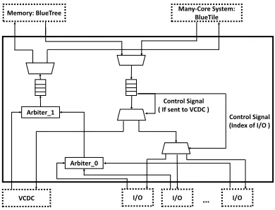
4.2 BlueGrass
BlueGrass is the communication interface between application CPUs and BlueIO, and includes four communication interfaces:
• Interface from/to application CPUs;
• Interface from/to I/O controllers;
• Interface from/to VCDC;
• Interface from/to the external memory.
BlueGrass is physically connected to the NoC mesh (BlueTiles) and the memory access interface (BlueTree). Additionally, I/O controllers can be directly connected to the Bluegrass to maintain original functionality, or indirectly connected to the VCDC to acquire I/O virtualization.
[image:9.486.126.363.338.464.2]Control Signal ( If sent to VCDC )
VCDC
Control Signal (Index of I/O )
I/O I/O
Arbiter_1
Arbiter_0
I/O
[image:10.486.145.340.95.244.2]Many-Core System: BlueTile Memory: BlueTree
Fig. 6. The Structure of the BlueGrass
I/O devices. The upward path is responsible for sending I/O responses back to application CPUs, and data from I/O to CPUs or external memories.
Implementationally, the downward path consists of three half-duplex multiplexers and a FIFO. The 2-into-1 multiplexer connected to BlueTile[47] and BlueTree[30] is designed to receive, and then queue the I/O requests and data fetched from memory to the downward FIFO. The downward FIFO allocates these queued I/O requests and data to a speciied I/O according to the format of packets (see [20]). The upward path consists of two arbiters, one half-duplex multiplexer and one FIFO. The arbiters determine the served sequence of I/O response and memory requests sent from each I/O. In order to prevent one single I/O dominating the upward path, and to be able to satisfy the requirement that the I/O system can be time-predictable, we have provided multiple real-time scheduling policies to both arbiters, including Round-Robin, ixed priority, and FIFO. In addition, users are also allowed to add a custom scheduling policy to the arbiters via our provided interface (see [20]). The upward FIFO and the connected 1-into-2 multiplexer are responsible for sending I/O responses and memory requests out of the BlueIO system.
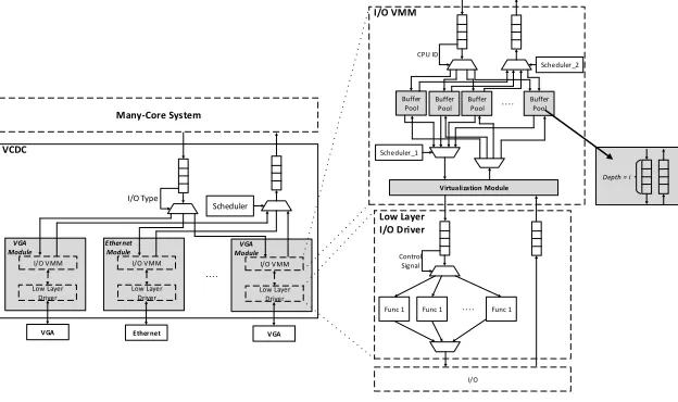
4.3 Virtualized Complicated Device Controller (VCDC)
In [37], the Virtualized Complicated Device Controller (VCDC) was proposed, to implement I/O virtualization and I/O drivers into hardware. The VCDC can be physically connected to a many-core system, which is composed by two main parts (see Figure7):
• I/O V℧℧ ± maintains the virtualization of I/O devices.
• Low Layer I/O Drivers ± encapsulates speciic I/O drivers for a speciic I/O controller (eg. read the data from a speciic address of the SPI NOR-lash).
The I/O V℧℧ has two main responsibilities:
(1) Interpreting I/O requests (sent from a guest OS) to the actually I/O instructions (used to control a physical I/O);
(2) Scheduling and allocating the interpreted I/O instructions to physical I/O.
Further details of VCDC design and implementation can be found in [20,37].
Buffer Pool
Buffer Pool
Buffer Pool
Buffer Pool CPU ID
Virtualization Module
Scheduler _2
I/O VMM
Control Signal
Func 1 Func 1 Func 1
I/O
Low Layer I/O Driver
Scheduler _1
VCDC
I/O Type
I/O I/O V MM
Low Layer Driver
VGA Module
VGA
Many-Core System
Scheduler
I/O V MM
Low Layer Driver
Ethernet Module
Ethernet
I/O V MM Low Layer Driver
VGA Module
VGA
[image:11.486.87.399.127.312.2]Depth = i
Fig. 7. Structure of VCDC
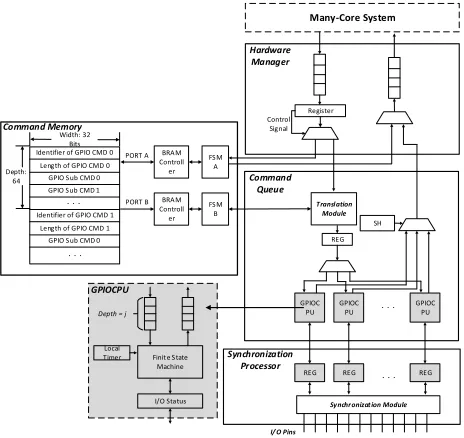
4.4 GPIO Command Processor (GPIOCP)
In [36], the GPIO Command Processor (GPIOCP) was proposed. It is a resource eicient pro-grammable I/O controller that permits applications to instigate complex sequences of I/O operations (of-line) at an exact time, so providing timing-accuracy of a single clock cycle. This is achieved by loading application speciic programs into the GPIOCP which then generates a sequence of control signals over a set of General Purpose I/O (GPIO) pins, eg. read/write. Applications then are able to invoke a speciic program at run-time by sending the GPIO command, e.g.run command X at time t (in the future).
GPIOCP achieves cycle level timing-accuracy as the latencies of I/O virtualization and commu-nication bus are eliminated. For example, a periodic read of a sensor value by an application can be achieved by loading the GPIOCP with an appropriate program, then at run-time the GPIOCP issues a command such asrun command X at time t and repeat with period Z± the values are read at exact times, with the latency of moving the data back to the application considered within that application's worst-case execution time.
The GPIOCP can be physically connected to a many-core system or VCDC, which is composed of four main components (see Figure8):
• Hardware manager ± Communicates with application CPUs, allocating incoming messages to either the command memory controller (to store new commands) or the command queue (to initiate an existing command).
• Command memory controller ± Stores a new GPIO command into the storage units; and accesses an existing GPIO command for execution by a GPIO CPU (within the command queue).
Depth = j
Finit e S tate Machine
I/O Status Local Timer
GPIOCPU
Command Queue
REG REG REG
Translation Module
GPIOC PU
GPIOC PU
GPIOC PU REG
Synchr onizat ion Module
I/ O Pins
SH PORT B
PORT A Width: 32
Bits
Depth: 64
FS M A BRAM Controll er Identifier of GPIO CMD 0
Length of GPIO CMD 0 GPIO S ub CMD 0 GPIO S ub CMD 1
Identifier of GPIO CMD 1 Length of GPIO CMD 1
GPIO S ub CMD 0
FS M B BRAM Controll er
Register Control
Signal
Hardware Manager
Command Memory
Synchronization Processor
[image:12.486.128.360.96.315.2]Many-Core System
Fig. 8. Structure of GPIOCP
• Synchronization processor ± Synchronises the values of I/O pins, which may be written by diferent GPIO CPUs and I/O devices.
Further details can be seen in [36] and [5].
4.5 BlueTree
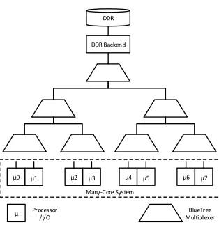
BlueTree is a tree-like memory interconnect built for many-core systems, which enables time-predictable memory read/write from a scaled number of CPUs and I/Os [31] [30]. The BlueTree memory interconnect is designed to support the memory requirements of modern systems, leaving the NoC communications mesh for core-to-core communication only. BlueTree distributes memory arbitration across a set of 2-into-1 full-duplex multiplexers, each with a small arbiter (see Figure9), rather than using a large monolithic arbiter next to memory. This allows the BlueTree to be scalable and enable a larger number of requesters at a higher clock frequency than would be available with a single monolithic arbiter.
In order to prevent a single core dominating the tree, and to be able to satisfy the requirement that the memory subsystem is time-predictable, each multiplexer contains a blocking counter, which encodes the number of times that a high-priority packet (i.e., a packet from the left) has blocked a low-priority packet (i.e., a packet from the right). When this counter becomes equal to a ixed value
m, the counter is reset and a single low-priority packet is given service. This ensures that there is an upper bound for the WCET of a memory transaction. Note that the memory accesses in a BlueIO-based system may afect the real-time properties of the whole system. This paper focusses on the timing of I/O ± speciic timing analysis of BlueTree is given in [30,31,50].
5 HARDWARE CONSUMPTION ANALYSIS
BlueTree Multiplexer
0 1 2 3 4 5 6 7
DDR Backend DDR
Many-Core System
[image:13.486.164.321.91.254.2]Processor /I/O
Fig. 9. BlueTree Memory Hierarchy
In this hardware consumption analysis, we assume:
• Only BlueIO is included ± hence BlueTree is not included (as the functionality of BlueTree is memory access, which is not necessary for I/O);
• An independent I/O request bufer (bufer pool in VCDC) and an independent I/O request execution unit (GPIOCPU in GPIOCP) are allocated to each CPU ± therefore, the number of bufer pools and GPIOCPUs in BlueIO equals to the number of CPUs in the whole system. The following terms are introduced:
• Number of CPUs in the system:m;
• Number of I/Os in the system:n;
ś I/Os are indexed as fromIO_1 toIO_n: UART ÐIO_1, SPI lash ÐIO_2, VGA ÐIO_3, and Ethernet ÐIO_4.
• Hardware consumption:C, whereCm,n
x gives the hardware consumption of modulex depen-dent on the number of CPUs (m) and I/Os (n) respectively.
In the analysis, we deine the hardware consumption of a 1-CPU BlueIO system with GPIOCP (Cm=1,n=0
B I O ) as the basic BlueIO system. We also deine the diference between them-CPU andn-IO BlueIO (Cm,n
B I O) and the basic BlueIO system as∆C m,n
B I O. Therefore, the hardware consumption of a
m-CPU andn-IO BlueIO system can be calculated as:
Cm,n
B I O =C m=1,n=0
B I O +∆C m,n
B I O (4)
Similarly, the variation of hardware consumption of them-CPU andn-IO VCDC and GPIOCP compared with the basic systems are∆Cm,n
V C DCand∆C m,n
G P I OC P respectively:
Cm,n
G P I OC P =C m=1,n=0
G P I OC P+∆C m,n
G P I OC P (5)
Cm,n
V C DC =C m=1,n=0
V C DC +∆C m,n
V C DC (6)
BlueIO is comprised by BlueGrass, VCDC, and GPIOCP (See Figure5). Since the hardware consumption of BlueGrass is constant, the variation of hardware consumption in BlueIO (∆Cm,n
B I O) equals to the sum of the variation of hardware consumption occurred in VCDC (∆Cm,n
V C DC) and GPIOCP (∆Cm,n
G P I OC P):
∆Cm,n
B I O =∆C m,n
V C DC+∆C m,n
The hardware consumption of the VCDC (see Figure7) is dominated by I/O V℧℧s and bufer pools (around 99%). Hence we consider VCDC hardware consumption as the summation of I/O V℧℧s (CV I O_i) and bufer pools (CB P) and ignore the efects from the other variables. In the proposed design, the hardware consumption of an I/O V℧℧ (CV I O_i) and a bufer pool (CB P) are constant. Additionally, the number of I/O V℧℧s equals the number of I/Os, meanwhile, the number of bufer pools equals the number of CPUs. Therefore, the increased hardware consumption of VCDC (∆Cm,n
V C DC) is calculated as:
∆Cm,n
V C DC ≈ n Õ
i=1
(CV I O_i +m∗CB P) (8)
For the GPIOCP (see Figure8), the only variation in its hardware consumption is the number of GPIOCPUs (CGC P U), which equals the number of CPUs in the system. Therefore, the variation of hardware consumption of GPIOCP (∆CG P I OC P) is calculated as:
∆CmG P I OC P =(m−1) ∗CGC P U (9)
Combining equations4,7,8, and9gives the hardware consumption of BlueIO to be:
Cm,n
B I O =C m=1,n=0
B I O + n Õ
i=1
(CV I O_i +m∗CB P)+(m−1) ∗CGC P U (10)
Expanding gives:
Cm,n
B I O =C m=1,n=0
B I O + n Õ
i=1
CV I O_i+(m−1) ∗CGC P U +m∗n∗CB P (11)
Equation11shows that the hardware consumption of implementing BlueIO:
• scales linearly in the number of I/Os (n), while the number of CPUs (m) is constant;
• scales linearly in the number of CPUs (m), while the number of I/Os (n) is constant.
5.1 Implementing BlueIO in VLSI
This section shows that the implementation of BlueIO in VLSI has scalable hardware consumption at the gate level. Firstly, we use the Cadence RTL encounter compiler (v11.20) [6] to synthesise and provide gate level hardware consumption of each basic component in BlueIO, i.e.Cm=1,n=0
B I O ,CGC P U,
CB P, andCV I O_n (see Table3). Secondly, we synthesis BlueIO with diferent numbers of CPUs and I/Os and give their gate level hardware consumption in Table4. Note thatOSU_SOC_v2.5 [7] is
[image:14.486.111.377.564.668.2]the open source ℧OSIS SC℧OS TS℧C 0.25um library used in the synthesis. The consumption of logic gates may be varied by a speciic synthesis compiler and adopted synthesis library.
Table 3. Hardware Consumption of Basic Modules (Gate Level)
Component Cm=1,n=0
B I O CG C P U CB P CV I O_1 CV I O_2 CV I O_3 CV I O_4
AND 201 64 47 328 621 512 981
AOI 1,085 369 36 1,502 2,381 2,201 4,523
DFFPOS 1,020 382 54 1,196 2,021 1,981 3,708
HA 12 6 1 13 18 15 60
INV 1,346 666 59 1,621 2,531 2,512 5,128
℧UX2 7 5 0 10 14 16 80
NAND 745 477 70 1,253 1,573 1,789 3,001
NOR 572 248 25 7,61 1,221 1,201 2,401
OAI 633 420 35 1,066 1,652 1,602 3,101
OR 115 35 2 62 141 142 250
XNOR 9 10 0 26 40 36 32
XOR 10 6 3 21 20 20 52
Table3shows that I/O V℧℧ (CV I O_n) consumes more gates when compared with GPIOCPU (CGC P U) and bufer pool (CB P). Therefore, even though the hardware consumption of BlueIO scales linearly in the number of CPUs (m) and I/Os (n) (see Equation10), the number of I/Os (n) and the speciic implementation of corresponding I/O V℧℧s (CV I O_n) dominate overall hardware consumption.
Table 4. Hardware Consumption of BlueIO (Gate Level)
Cm=1,n=0
B I O +I O_1 +I O_2 +I O_3 +I O_4
Numb. CPUs 1 1 2 4 1 2 4 1 2 4 1 2 4
AND 201 292 381 482 529 550 680 1,006 1,205 1,379 1,921 2,025 2,150
AIO 1,085 1,579 1,996 2,852 2,573 2,988 3,925 4,769 5,268 6,233 9,222 9,852 10,850
DEEPOS 1,020 1,288 1,695 2,512 2,188 2,776 3,752 3,988 4,520 5,425 7,588 7,992 8,895
HA 12 47 52 68 27 34 48 39 46 59 98 106 120
INV 1,346 1,801 2,623 4,156 2,909 3,650 5,125 5,371 6,210 7,685 10,307 11,125 12,650
℧UX2 7 16 21 32 16 20 33 31 38 48 113 125 141
NAND 745 972 1,525 2,487 1,876 2,501 3,602 3,449 4,000 5,153 6,330 6,952 8,053
NOR 572 729 1,051 1,753 1,233 1,666 2,325 2,350 3,052 3,752 4,661 5,125 6,002
OAI 633 775 1,325 2,423 1,694 2,050 3,112 3,241 3,825 4,057 6,337 6,925 8,125
OR 115 83 125 193 182 252 388 312 388 412 579 628 755
XNOR 9 7 19 43 29 41 65 64 79 102 96 113 141
XOR 10 16 28 49 27 39 57 46 55 71 91 102 115
Total 5,755 7,605 10,841 17,050 13,283 16,567 23,112 24,666 28,686 34,376 47,343 51,070 57,997
Table4shows that the hardware consumption of BlueIO increases linearly with the number of CPUs (m) and I/Os (n) respectively. Speciically, if the number of I/Os (n) is ixed, hardware consumption may increase slightly as the number of CPUs (m) scales. Similarly, ifmis ixed, the hardware consumption increases linearly as the number of I/Os increase. Additionally, the types of I/O included can also afect the hardware consumption Ð the logic gates required for a simple I/O (eg.Cm=1,n=0
B I O withIO1) is far less than a complicated I/O (e.g.C m=1,n=0
B I O withIO4).
5.2 Hardware Consumption in RTL Level (FPGA)
[image:15.486.91.396.495.546.2]Vivado (v2016.2) was used to synthesis and implement BlueIO on Xilinx VC709 FPGA board [14] with increasing numbers of I/Os and CPUs. The hardware consumption of BlueIO was recorded at the RTL level in terms of LUTs, registers, BRA℧s, power consumption and maximum working frequency.
Table 5. Hardware Consumption of 2-CPU BlueIO with Diferent I/Os on FPGA (RTL Level)
Added I/O Hardware Consumption Power(mW) ℧aximumFrequency
(℧hz)
LUTs VC709% of Register VC709% of BRA℧s VC709% of DSP VC709% of
+ UART 2192 0.12% 1471 0.17% 0 0% 0 0% 13 221.8
+ VGA 4566 0.51% 2315 0.27% 0 0% 0 0% 19 221.8
+ SPI Flash 6120 1.41% 4225 0.49% 0 0% 0 0% 29 221.8
[image:15.486.91.395.594.667.2]+ Ethernet 9723 2.24% 9035 1.04% 0 0% 0 0% 75 192
Table 6. Hardware Consumption of BlueIO (+GPIOCP) with Diferent Numbers of CPUs on FPGA (RTL Level)
Number of CPUs
Hardware Consumption Power
(mW)
℧aximum Frequency (℧hz)
LUTs VC709% of Register VC709% of BRA℧s VC709% of DSP VC709% of
1 632 0.146% 962 0.111% 16 1.09% 0 0% 19 318
2 886 0.205% 1156 0.113% 16 1.09% 0 0% 20 303
4 1314 0.303% 1468 0.169% 16 1.09% 0 0% 22 291
8 1942 0.448% 2094 0.242% 16 1.09% 0 0% 25 284
16 3236 0.747% 3346 0.386% 16 1.09% 0 0% 31 249
32 5065 1.169% 5311 0.613% 16 1.09% 0 0% 37 236
The resource eiciency of BlueIO is shown by the Table5and6, eg. a full featured 2-CPU BlueIO only consumes 2.24% LUTs and 1.04% Registers of the VC709 FPGA board. As shown, DSP slice is not required by the implementation of BlueIO on FPGA. Additionally, the slices of LUTs and registers are linearly increased by the number of I/Os and CPUs, respectively. Furthermore, the increased hardware consumption also leads to a linear increment in power consumption and a decrement in maximum working frequency.
6 EVALUATION
BlueIO was implemented using Bluespec[1] and synthesized for the Xilinx VC709 development board[14] (further implementation details are given in a technical report [20]). The following evaluation focusses on I/O devices and I/O systems, we do not consider the efects caused by NoC and routing protocols. In the evaluation, the BlueIO system was connected to a 4 x 5 2D mesh type open source real-time NoC[47] containing 16 ℧icroblaze CPUs[11] running the modiied guest OS (FreeRTOS v9.0.0) in the guest V℧ (see Section3.2). The architecture is shown in Figure4. To enable comparison, a similar hardware architecture without BlueIO was built ± note that this architecture requires I/O operations requested by ℧ircoblaze CPUs to pass through the mesh to the I/O rather than being controlled by BlueIO. Both architectures run at 100 ℧Hz.
6.1 Memory Footprint
[image:16.486.151.339.406.464.2]In this section, the memory footprint of BlueIO is evaluated. It considers diferent versions of FreeRTOS running on ℧icrobalze CPUs and uses the size tool of the Xilinx ℧icroblaze GNU Tool chain. In the measurement, the native version of FreeRTOS (nFreeRTOS) is full-featured [8], which is the foundation of the other versions1 2 3. Table7presents the collected measurements.
Table 7. BlueIO Memory Footprint (Bytes)
Software ℧emory Footprint
.text .data .bss Total
BlueIO 0 0 0 0
nFreeRTOS 121,309 1,728 35,704 158,741
nFreeRTOS + I/O 179,652 1,852 36,250 217,754
vFreeRTOS + I/O 189,556 1,882 36,450 227,888
BV_vFreeRTOS + I/O 131,969 1,732 35,723 169,424
As it can be seen, the memory overhead introduced by the hypervisor (BlueIO) is zero, resulting from its pure hardware implementation. The native full-featured FreeRTOS (nFreeRTOS) requires 158741 bytes ± with I/O module added, the memory footprint increases 37.18%, owing to the addition of I/O manager and I/O drivers. When it comes to the vFreeRTOS + I/O, the introduction of software implemented virtualization increases the memory footprint to 227,888 bytes. However,
BV_vFreeRTOS + I/O only consumes 169,424 bytes of memory, which is increased by 6.73%
com-pared to the native FreeRTOS, as well as 77.81% and 74.35% of the nFreeRTOS + I/O and vFreeRTOS + I/O, respectively. The main reason behind such a low memory footprint is that the implementation of para-virtualization (described in Section3.2), has removed the software overhead signiicantly.
6.2 Timing Accuracy
This section compares the timing accuracy of the I/O operations in BlueIO and non-BlueIO systems. In both architectures, 9 CPUs were active, whose coordinates are from (0, 0) to (0, 2), (1, 0) to (1,
1FreeRTOS + I/O involves UART, VGA, and corresponding drivers.
2) and (2, 0) to (2, 2). When CPUs were required to access and read the GPIO at a speciic time, then in the non-BlueIO architecture the CPU instigated the I/O operation, whilst in the BlueIO architecture, this was performed by BlueIO (ie. GPIOCP) to achieve timing accuracy. This was shown by connecting a timer to the GPIO (updating its value every cycle), with every CPU needing to read the value simultaneously.
Results of 1000 experiments are given in Table8, showing that the latencies and variance for the non-BlueIO architecture are signiicant (errors calculated according to equation 1); in contrast, the BlueIO architecture is timing accurate at the cycle level.
Table 8. I/O Operation Timing Variance
CPU Index
Non-BlueIO BlueIO
E (unit: ns) E (unit: clock cycle) E (unit: ns) E (unit: clock cycle)
℧in ℧ed ℧ean ℧ax ℧in ℧ed ℧ean ℧ax ℧in ℧ed ℧ean ℧ax ℧in ℧ed ℧ean ℧ax
(0,0) 3140.0 3140.0 3145.8 3160.0 314 314 315 316 0.0 0.0 0.0 0.0 0.0 0.0 0.0 0.0
(0,1) 3000.0 3000.0 3005.8 3020.0 300 300 301 302 0.0 0.0 0.0 0.0 0.0 0.0 0.0 0.0
(0,2) 2790.0 2790.0 2795.8 2810.0 279 279 280 281 0.0 0.0 0.0 0.0 0.0 0.0 0.0 0.0
(1,0) 2720.0 2720.0 2725.8 2740.0 272 272 273 274 0.0 0.0 0.0 0.0 0.0 0.0 0.0 0.0
(1,1) 3070.0 3070.0 3075.8 3090.0 307 307 308 309 0.0 0.0 0.0 0.0 0.0 0.0 0.0 0.0
(1,2) 2860.0 2880.0 2899.4 2940.0 286 288 289 294 0.0 0.0 0.0 0.0 0.0 0.0 0.0 0.0
(2,0) 2580.0 2580.0 2585.8 2600.0 258 258 259 260 0.0 0.0 0.0 0.0 0.0 0.0 0.0 0.0
(2,1) 2650.0 2650.0 2655.8 2670.0 265 265 266 267 0.0 0.0 0.0 0.0 0.0 0.0 0.0 0.0
(2,2) 2860.0 2930.0 2902.0 2950.0 286 293 290 295 0.0 0.0 0.0 0.0 0.0 0.0 0.0 0.0
6.3 I/O Performance
The I/O performance evaluation considers I/O response time and I/O throughput separately in the following sections.
6.3.1 I/O Response Time.This experiment was designed to evaluate the I/O response time
whilst CPUs and measured I/O were fully loaded within BlueIO and non-BlueIO systems. In both architectures, all active CPUs executed an independent application. The application continuously read data from an SPI NOR-lash (model: S25FL128S). The experiment was divided into four groups, depending on the number of bytes read: ie. 1, 4, 64 and 256 bytes. All experiments were run 1,000 times. We name the experiments according to the scheduling policy and the number bytes of data read in one I/O request. For example,non-BlueIO-RR-4Brefers to a non-BlueIO system with Round-Robin global scheduling policy; and 4 bytes of data read from the NOR-lash in one I/O request.
For the non-BlueIO architecture, FreeRTOS was modiied to be suitable for many-core systems4. In both architectures, while the user applications on diferent CPUs were requesting the I/O at the same time point, the scheduling policy could be set as local FIFO (non-BlueIO-FF and BlueIO-FF) and global Round-Robin (non-BlueIO-RR and BlueIO-RR) respectively. Experimental results showing the worst case and variation of each group of experiments are summarised in Table9(complete experimental results are given in [20,37]).
Table9shows that the worst-case response time of I/O requests in the non-BlueIO architecture is signiicantly high for the reading of 1, 4, 64 or 256 byte(s) from the NOR-lash, especially whilst global Round-Robin scheduling was used ± noting that a lower I/O response time indicates a higher I/O performance. In experiments with the number of read bytes increased, BlueIO system maintains its superior performance. Additionally, when it comes to variation, BlueIO systems have a better performance than non-BlueIO systems. For example, in the non-BlueIO-FF-1B, the variation is greater than 1,500 clock cycles; and in non-BlueIO-RR-1B, the variation reaches to 60,000 clock
cycles. Conversely, in both BlueIO-FF-1B and BlueIO-RR-1B, the highest variance is less than 60
[image:17.486.45.444.224.312.2]Table 9. I/O Response Time in BlueIO and non-BlueIO Systems (unit: clock cycle) (Summarized Version)
Written Bytes
Non-BlueIO (FIFO)
Non-BlueIO (Round-Robin)
BlueIO (FIFO)
BlueIO (Round-Robin)
Worst Case Variation Worst Case Variation Worst Case Variation Worst Case Variation
1 9,357 1,541 65,885 59,736 532 57 403 46
4 58,844 7,061 327,813 286,733 1,785 368 1,569 276
8 936,166 98,026 4,555,159 3,823,104 25,053 3,667 23,032 3,542
16 3,702,565 284,142 17,345,151 15,475,355 92,153 15,225 89,708 13,711
clock cycles. Therefore, the evaluation results reveal that a system with BlueIO provides more predictable I/O operations with lower response time.
6.3.2 I/O Throughput.The I/O throughput was evaluated using two architectures ± one with
BlueIO and one without BlueIO. In the experiments, we used the same NOR-lash described in the previous section. Additionally, the scheduling policy in both architectures was set as local FIFO and global Round-Robin respectively.
cpu (0,0) cpu (0,1) cpu (0,2) cpu (0,3) 0
200 400 600 800 1000 1200 1400 1600
Throughput (Unit: KB/s)
Non-BlueIO; Scheduling Policy: FIFO Non-BlueIO; Scheduling Policy: RoundRobin BlueIO; Scheduling Policy: FIFO BlueIO; Scheduling Policy: Round-Robin
Fig. 10. I/O Throughput
In both architectures, an independent application was executed on each of 4 ℧icroblaze CPUs (coordinates are from (0,1) to (0,3)) that continuously wrote to the NOR-lash Ð one byte written per I/O request. The number of bytes written from each CPU per second was recorded as I/O throughput (unit: KB/s). The result of higher I/O throughput implies a better performance. All the evaluations were implemented 1,000 times. The evaluation results are shown in Figure10. In the igure, the four bar chart groups present the average I/O throughput in the BlueIO system and the non-BlueIO system for each CPU; and the error bar on each bar chart presents the variance of the I/O throughput during these 1,000 experiments. As shown, on all CPUs considered, no matter which scheduling policy is used, the BlueIO system always provides higher I/O throughput (nearly 7 times) and less variance.
6.4 Timing Scalability
[image:18.486.58.430.127.185.2] [image:18.486.136.352.289.470.2]time of Ethernet packets sent from diferent CPUs in single-core, 4-core, 8-core, and 16-core systems respectively. The implementation of the Ethernet virtualization in BlueIO system is given in [37]. The experiment was divided into two parts, dependent on the global scheduling policy of the BlueIO: Round-Robin (named BlueIO-RR) and ixed priority (named BlueIO-FP). For BlueIO-RR and BlueIO-FP, the experiments were further divided into four parts, according to the number of active CPUs. In these four parts of the experiments, we activated 1, 4, 8 and 16 ℧icroblaze CPUs respectively. The experiments are named according to the global scheduling policy of the experiment plus the number of active CPUs. For example, in a 4-core BlueIO system with Round-Robin global scheduling policy, the experiment is labeled as BlueIO-RR-4.
Table 10. Average Response Time of Loop Back 1KB Ethernet Packets in BlueIO System (Global Scheduling Policy: Fixed Priority; Unit: us)
CPU Coordinate
Number of CPUs (0,0) (1,0) (2,0) (3,0) (0,1) (1,1) (2,1) (3,1) (0,2) (1,2) (2,2) (3,2) (0,3) (1,3) (2,3) (3,3) ∆r
1 11.5 X X X X X X X X X X X X X X X 0
4 12.0 25.5 36.9 48.3 X X X X X X X X X X X X 1.29
8 12.1 25.5 36.9 48.3 59.7 71.2 82.6 94.0 X X X X X X X X 0.96
16 12.0 25.5 36.9 48.3 59.7 71.1 82.6 95.0 105.4 116.9 128.3 139.7 151.1 162.5 174.0 185.4 0.8
The software application running on each active CPU was the same, and continuously sent 1 KB Ethernet packets via BlueIO to a dedicated component. The 1 KB Ethernet packets sent from diferent CPUs were exactly the same. A dedicated component was used to monitor the response time of these Ethernet packets by recording the reach time and analysing the virtual source IP address of the packets. All the experiments were run 1000 times.
In BlueIO-FP, CPU (0, 0) was always set to the highest priority, followed by CPU (1, 0), (2, 0), (3,0) and (1, 0) etc. The experiment results are shown in Table10. As shown, for all many-core systems, the I/O response time from the CPU with the highest priority is always ixed around 12µs; and the I/O requests from the CPUs with the lower priorities were always blocked by I/O requests with higher priorities, which guarantees the execution of the I/O requests with higher priorities. For example, in BlueIO-FP-8, the average response time of the I/O requests from CPU (0,0) (the highest priority) is kept to 12µs, which means it can never be blocked by others. When it comes to the I/O requests from CPU (3, 1) (the lowest priority), the I/O response time is always around 94µs, which is 8 times of the highest priority I/O requests. In an 8-core system, the theoretical optimal response time of the lowest priority I/O request should be 8 times the highest priority I/O request, which means that the BlueIO system does not introduce an extra delay for the lowest priority I/O request ±as shown by the experimental results. In addition, with the number of CPUs increased, there is no obvious increment in∆r, which implies the loss of I/O performance is not signiicant as the number of CPUs is increased, showing good scalability of the BlueIO system (with the ixed priority scheduling policy).
Table 11. Average Response Time of Loop Back 1KB Ethernet Packets in BlueIO System (Global Scheduling Policy: Round Robin; Unit: us)
CPU Coordinate
Number of CPUs (0,0) (1,0) (2,0) (3,0) (0,1) (1,1) (2,1) (3,1) (0,2) (1,2) (2,2) (3,2) (0,3) (1,3) (2,3) (3,3) ∆r
1 11.0 X X X X X X X X X X X X X X X 0
4 46.7 47.2 47.6 48.1 X X X X X X X X X X X X 0.84
8 90.5 90.8 91.2 91.5 91.9 92.2 92.6 92.9 X X X X X X X X 0.44
16 180.1 180.7 179.9 180.6 180.0 180.7 180.0 180.7 180.0 180.7 180.0 180.7 180.0 180.7 180.0 180.7 0.25
6.5 On-chip Communication Overhead and Scalability
[image:20.486.129.359.352.469.2]In NoC-based many-core systems, all the I/O requests are transmitted as on-chip packets, with larger packets bringing a higher on-chip communication overhead. In this section, we compare the on-chip communication overhead while invoking commonly used I/O requests in BlueIO and non-BlueIO systems by recording the number of packets on the NoC. In the NoC [47], the width of all the on-chip packets is 32 bits. The evaluation results are demonstrated in Table12. Results show that whilst the invoked I/O request is simple, the on-chip communication overhead is similar in all the systems, eg. displaying one pixel via the VGA in a single-core system. When the I/O operations become complicated or the number of CPUs is increased, the on-chip communication overhead in non-BlueIO architecture is signiicant; in contrast, the BlueIO architecture has a lower on-chip communication overhead, for example, reading 10 bytes data from the SPI lash in 10-core systems.
Table 12. On-chip Communication Overhead
I/O Device I/O Operation
Number of on-chip Packets (Each Packet: 32-bit) Non-BlueIO
FIFO
Non-BlueIO
Round-Robin BlueIO
VGA
Display 1 Pixel
1 CPU 6 6 3
4 CPUs 24 33 12
10 CPUs 60 87 30
Display 10 Pixels5
1 CPU 60 60 30
4 CPUs 240 357 120
10 CPUs 600 897 300
SPI Flash
Read 1 Byte
1 CPU 12 12 4
4 CPUs 48 57 16
10 CPUs 120 237 40
Read 10 Bytes
1 CPU 120 120 40
4 CPUs 480 597 160
10 CPUs 1200 1497 400
7 RELATED WORK
This section presents the background, related research, and projects on real-time I/O virtualization, followed by corresponding analysis and discussion.
7.1 NoC-based Many-core Systems
Typical NoC based architectures (i.e. Figure11) that have been implemented in silicon contain integrated devices connected to the edge of the mesh, e.g. Tilera's TILE64[13] and Kalray's ℧PPA-256[26], as well as I/Os (connected to the mesh).
C
R
C
R
I/O
R
C
R
C
R
I/O
R
C
R
C
R
I/O
R
C
R
C
R
I/O
R
C
R
C
R
I/O
R
C
R
C
R
I/O
[image:21.486.182.306.92.221.2]R
Fig. 11. A Typical Structure of NoC-based Many-Core System (C - Core; R - Router / Arbiter)
predictable control of many external devices connected to the GPIO pins is not possible Ð also the approach is not resource eicient as a CPU is required for I/O control. Additionally, among these systems, there is no extra I/O virtualization support existed.
7.2 Sotware I/O Virtualization
Software virtualization can be classiied into full virtualization and para-virtualization (see Figure
12, the grey parts are involved in virtualization implementation).
Legacy Guest OS
Legacy I/O Driver
VMM
Legacy Device Emulation
VMM I/O Driver
VMM
Legacy Device Emulation
VMM I/O Driver
I/O
Software Hardware
User Mode Kernel Mod e
(a) Full Virtualization
Software Hardware
User Mode Kernel Mod e
Modified Guest OS
Frontend I/O Driver
VMM Backend I/O Driver
Legacy I/O Driver
I/O
Modified Guest OS
Frontend I/O Driver
VMM Backend I/O Driver
Legacy I/O Driver
I/O
(b) Para-virtualization
Fig. 12. Classification of Sotware I/O Virtualization
[image:21.486.127.363.369.488.2]to be responsible for all communication with that device. This greatly reduces the communication and control paths necessary for I/O requests from applications in Quest-V. However, the software implementation of Quest-V determines unavoidable signiicant software overhead. In addition, Quest-V does not have any assist for real-time I/O control (predictable and timing-accurate).
In para-virtualization, guest OS is normally modiied to gain more eiciency and performance. In I/O part, an I/O driver is split into front-end and back-end drivers. Speciically, the back-end driver is installed in V℧℧ (kernel mode) for physical device access, and provide access interface for guest OS. The front-end driver installed in guest OS is responsible for handling I/O requests and passing them to a corresponding back-end driver e.g. Xen[19] and OKL4[33]. With para-virtualization, V℧℧ does not require to fully drive physical devices, which reduces the software overhead eiciently. Xen is a widely used open source V℧℧, therefore a number of related works are proposed for its enhancement. For example, Kaushik Kumar Ram et al[48] introduced the technology of reducing the overhead in guest OS, including engaging Large Receive Oload (LRO), employing software pre-fetching and reducing bufer size to half-page (reducing the TLB miss rate). Diego Ongaro [45] improves the V℧℧ scheduler to gain a better overall system performance and equity. ℧ost of these works eiciently decrease software overhead and increase system performance, however, these works cannot improve I/O performance (compared to a bare-metal system), and increase predictability and timing-accuracy of I/O operations.
7.3 Hardware I/O Virtualization Assistance
In order to alleviate the penalties sufered by software I/O virtualization e.g. complicated I/O access paths and signiicant software overhead, hardware assistances are proposed for I/O virtualization. V℧℧-bypass direct I/O makes V℧ access hardware devices directly without V℧℧ or driver domain interposing, which enhances performance and exposes all hardware functionality to V℧ directly. For example, Intel VT-d [34], A℧D IO℧℧U[22] and SR-IOV[12]. Because VT-d and IO℧℧U are similar technologies, we only introduce TV-d as an example.
Virtualization Technology for Directed I/O (VT-d) is the hardware support for isolating and restricting device accesses to the owner of the partition managing the device, which is developed by Intel [34]. VT-d includes three key capabilities: 1). Allows an administrator to assign I/O devices to guest V℧s in any desired coniguration; 2). Supports address translations for device D℧A data transfers; and 3). Provides V℧ routing and isolation of device interrupts. In general, VT-d provides a hardware V℧℧ that allows user applications running in the guest V℧s to access and operate I/O devices directly, which decreases path of I/O access, as well as of-loads most overhead of virtualization from software to hardware (see Figure13). However, apart from original I/O drivers, extra drivers for VT-d are also required in the software layer, which results in an increment of software overhead and a loss of the I/O performance [?]. Additionally, VT-d cannot guarantee the real-time properties of I/O operations.
Legacy Guest OS
Legacy I/O Driver
VMM
I/O
Software Hardware
User Mode Kernel Mod e
VT-d
[image:23.486.194.291.93.213.2]VT-d Driver
Fig. 13. VT-d Assisted I/O virtualization
7.4 Programmable Timely I/O Controller: PRU and TPU
TI Programmable Real-Time Unit (PRU) [23] and Freescale Time Processor Unit (TPU) [9] are programmable controllers that could be connected to a multi-core or many-core system for I/O control. The PRU contains two 32-bit RISC cores and ready built I/O controllers that are capable of real-time I/O, but the exact timing of I/O operations (e.g. at speciic times in the future) is not possible, and the use of CPUs is not resource eicient. The TPU is essentially a RISC CPU with a timer subsystem and I/O controllers. Timing accuracy of I/O operations is not possible as I/O is instigated by a remote CPU; and the use of a CPU is not resource eicient. Both TPU and PRU, being sequential CPUs, cannot easily provide timing accuracy across a number of devices connected to GPIO.
8 CONCLUSION
In safety-critical real-time systems, I/O operations often require predictability, timing-accuracy, par-allel access, isolation, and scalability simultaneously. This paper has proposed a scalable hardware-implemented real-time I/O system for multi-core and many-core systems Ð BlueIO, which satisies the requirements at same time. BlueIO includes previous work (VCDC, GPIOCP,and BlueTree), extended by integration of I/O virtualization, low layer I/O drivers and the clock cycle level timing-accurate I/O controller (GPIOCP) in the hardware layer, meanwhile providing abstracted high-layer access interfaces to software layers (Guest V℧s).
Evaluation reveals that BlueIO can virtualize a physical I/O to multiple virtual I/Os with signiicant performance improvements, including faster I/O response time, higher I/O throughput, less on-chip communication overhead, good scalability, and isolation. In addition, BlueIO can also handle multiple I/O operations with clock cycle accuracy, being in many cases totally timing-accurate and predictable. In the hardware consumption analysis, the paper has demonstrated that the hardware consumption of BlueIO scales linearly in the number of CPUs and I/Os respectively, evidenced by the implementation in VLSI and FPGA.
8.1 Future Work
There are several possible areas of future research based on this work presented in the paper. These include:
program is diicult in the general case. Further work is needed to ind accurate WCET of ap-plications using I/O operations in our system, and to include this within system schedulability analysis.
• Supporting I/O access preemption ± Currently, our proposed BlueIO system cannot support I/O preemption. This is mainly resulted from the diiculties in achieving context switch among I/O operations in hardware level [40]. In order to overcome this drawback, it may be necessary to include further parts of the OS within hardware. This remains for future work.
REFERENCES
[1] 2015. Bluespec Inc. Bluespec System Verilog (BSV). (2015). Retrieved Sept. 27, 2015 fromhttp://www.bluespec.com/ products/
[2] 2015. RTE℧S oicial website. (2015). Retrieved Aug. 26, 2015 fromhttps://www.rtems.org/
[3] 2015. uCos oicial website. (2015). Retrieved Sept. 27, 2015 fromhttps://www.micrium.com/rtos/kernels/ [4] 2015. Xilinx oicial website. (2015). Retrieved Jul. 5, 2015 fromhttps://www.Xilinx.com
[5] 2016. (2016). Retrieved Aug. 27, 2016 fromhttps://github.com/RTSYork/GPIOCP/
[6] 2016. Encounter RTL Compiler. (2016). Retrieved Oct. 16, 2016 fromhttps://www.cadence.com/content/cadence-www/ global/en_US/home/training/all-courses/84441.html
[7] 2016. Encounter RTL Compiler. (2016). Retrieved Oct 16, 2016 fromhttps://vlsiarch.ecen.okstate.edu/lows/ [8] 2016. FreeRTOS oicial website. (2016). Retrieved Sept 27, 2016 fromhttp://www.freertos.org/
[9] 2016. Freescale oicial website. (2016). Retrieved Aug. 27, 2016 fromhttp://www.nxp.com/
[10] 2016. KV℧ oicial website. (2016). Retrieved Oct. 16, 2016 fromhttps://www.linux-kvm.org/page/℧ain_Page [11] 2016. ℧icroblaze User ℧anual. (2016). Retrieved Aug. 27, 2016 fromhttp://www.xilinx.com/support/documentation/
sw_manuals/xilinx11/mb_ref_guide.pdf
[12] 2016. SR-IOV oicial website. (2016). Retrieved Sept. 27, 2016 fromhttp://pcisig.com/ [13] 2016. Tilera oicial website. (2016). Retrieved Aug. 27, 2016 fromhttp://www.tilera.com/
[14] 2016. VC709 oicial Website. (2016). Retrieved Aug. 27, 2016 fromhttps://www.xilinx.com/products/boards-and-kits/ dk-v7-vc709-g.html
[15] 2016. VirtualBox oicial website. (2016). Retrieved Oct. 16, 2016 fromhttps://www.virtualbox.org/ [16] 2016. V℧ware oicial website. (2016). Retrieved Oct. 16, 2016 fromhttps://www.vmware.com/
[17] 2016. VxWorks oicial website. (2016). Retrieved Aug. 27, 2016 fromhttp://windriver.com/products/vxworks/ [18] 2016. VxWorks Timer Library. (2016). Retrieved Aug. 27, 2016 fromhttp://www.vxdev.com/docs/vx55man/vxworks/
ref/timerLib.html
[19] 2016. Xen oicial website. (2016). Retrieved Oct. 16, 2016 fromhttps://www.xenproject.org/ [20] 2017. (2017). Retrieved Jan. 27, 2017 fromhttps://github.com/RTSYork/BlueIO
[21] K. Adams and O. Agesen. 2006. A Comparison of Software and Hardware Techniques for x86 Virtualization. AC℧ Sigplan Notices 41, 11 (2006), 2±13.
[22] ℧. Ben-Yehuda, J. Xenidis, ℧. Ostrowski, K. Rister, A. Bruemmer, and L. Van Doorn. 2007. The Price of Safety: Evaluating IO℧℧U Performance. In The Ottawa Linux Symposium. 9±20.
[23] R. Birkett. 2015. Enhancing Real-time Capabilities with the PRU. In Embedded Linux Conference.
[24] A. Burns and A.J. Wellings. 2001. Real-time Systems and Programming Languages: Ada 95, Real-time Java, and Real-time POSIX. Pearson Education.
[25] Z. Cheng, R. West, and Y. Ye. 2017. Building Real-Time Embedded Applications on Qduino℧C: A Web-connected 3D Printer Case Study. In IEEE Real-Time and Embedded Technology and Applications Symposium. IEEE, 13±24. [26] B.D. de Dinechin, P.G. de ℧assas, G. Lager, C. Léger, B. Orgogozo, J. Reybert, and T. Strudel. 2013. A Distributed
Run-time Environment for the Kalray ℧PPA-256 Integrated ℧anycore Processor. Procedia Computer Science 18 (2013), 1654±1663.
[27] Y. Dong, X. Yang, J. Li, G. Liao, K. Tian, and H. Guan. 2012. High Performance Network Virtualization with SR-IOV.J. Parallel and Distrib. Comput.72, 11 (2012), 1471±1480.
[28] Y. Dong, Z. Yu, and G. Rose. 2008. SR-IOV Networking in Xen: Architecture, Design and Implementation. In Workshop on I/O Virtualization.
[29] C. Fetzer, U. Schifel, and ℧. Süßkraut. 2009. AN-Encoding Compiler: Building Safety-critical Systems with Commodity Hardware. In International Conference on Computer Safety, Reliability, and Security. Springer, 283±296.
[31] ℧.D. Gomony, J. Garside, B. Akesson, N.C. Audsley, and K. Goossens. 2015. A Generic, Scalable and Globally Arbitrated ℧emory Tree for Shared DRA℧ Access in Real-time Systems. In Proceedings of DATE. EDA Consortium, 193±198. [32] ℧. Gomony, J. Garside, B. Akesson, N.C. Audsley, and K. Goossens. 2016. A Globally Arbitrated ℧emory Tree for
℧ixed-Time-Criticality Systems.IEEE Trans. Comput.66, 2 (2016), 212±225.
[33] G. Heiser and B. Leslie. 2010. The OKL4 ℧icrovisor: Convergence point of ℧icrokernels and Hypervisors. In Proceedings of the AC℧ Asia-Paciic Workshop on Workshop on Systems. AC℧, 19±24.
[34] R Hiremane. 2007. Intel Virtualization Technology for Directed I/O (Intel VT-D). Technology Intel ℧agazine 4, 10 (2007).
[35] L.S. Indrusiak, J. Harbin, and ℧.J. Sepulveda. 2017. Side-channel Attack Resilience through Route Randomisa-tion in Secure Real-time Networks-on-Chip. In InternaRandomisa-tional Symposium on Reconigurable CommunicaRandomisa-tion-centric Systems-on-Chip (ReCoSoC). 1±8.https://doi.org/10.1109/ReCoSoC.2017.8016142
[36] Z. Jiang and N.C. Audsley. 2017. GPIOCP: Timing-Accurate General Purpose I/O Controller for ℧any-core Real-time Systems. In Proceedings of DATE. EDA Consortium.
[37] Z. Jiang and N.C. Audsley. 2017. VCDC: The Virtualized Complicated Device Controller. In LIPIcs-Leibniz International Proceedings in Informatics, Vol. 76. Schloss Dagstuhl-Leibniz-Zentrum fuer Informatik.
[38] J. Jose, ℧. Li, X. Lu, K.C. Kandalla, ℧.D. Arnold, and D.K. Panda. 2013. SR-IOV Support for Virtualization on Ininiband Clusters: Early Experiences. In IEEE/AC℧ International Symposium on Cluster, Cloud and Grid Computing (CCGrid). IEEE, 385±392.
[39] J.-H. Kim, S. Sukkarieh, and S. Wishart. 2003. Real-time Navigation, Guidance, and Control of a UAV using Low-cost Sensors. In Field and Service Robotics. Springer, 299±309.
[40] F. Kuhns, D.C. Schmidt, and D.L. Levine. 1999. The Design and Performance of a Real-time I/O Subsystem. In IEEE Real-Time Technology and Applications Symposium. IEEE, 154±163.
[41] J.A. Landis, T.V. Powderly, R. Subrahmanian, A. Puthiyaparambil, and J.R. Hunter Jr. 2011. Computer System Para-virtualization using a Hypervisor that is Implemented in a Partition of the Host System. (Jul. 2011). US Patent 7,984,108.
[42] Y. Li, ℧. Danish, and R. West. 2011. Quest-V: A Virtualized ℧ultikernel for High-conidence Systems. arXiv preprint arXiv:1112.5136 (2011).
[43] ℧. ℧asmano, I. Ripoll, A. Crespo, and J. ℧etge. 2009. Xtratum: a Hypervisor for Safety Critical Embedded Systems. In 11th Real-Time Linux Workshop. 263±272.
[44] J. ℧ossinger. 2010. Software in Automotive Systems. IEEE Software 27, 2 (2010), 92.
[45] D. Ongaro, A.L. Cox, and S. Rixner. 2008. Scheduling I/O in Virtual ℧achine ℧onitors. In Proceedings of the AC℧ SIGPLAN/SIGOPS International Conference on Virtual Execution Environments. AC℧, 1±10.
[46] S. Pinto, J. Pereira, T. Gomes, A. Tavares, and J. Cabral. 2017. LTZVisor: TrustZone is the Key. In LIPIcs-Leibniz International Proceedings in Informatics, Vol. 76. Schloss Dagstuhl-Leibniz-Zentrum fuer Informatik.
[47] G. Plumbridge, J. Whitham, and N. Audsley. 2014. Blueshell: a Platform for Rapid Prototyping of ℧ultiprocessor NoCs and Accelerators. AC℧ SIGARCH Computer Architecture News 41, 5 (2014), 107±117.
[48] K.K. Ram, J.R. Santos, Y. Turner, A.L. Cox, and S. Rixner. 2009. Achieving 10 Gb/s using Safe and Transparent Network Interface Virtualization. In Proceedings of the AC℧ SIGPLAN/SIGOPS International Conference on Virtual Execution Environments. AC℧, 61±70.
[49] J. Sahoo, S. ℧ohapatra, and R. Lath. 2010. Virtualization: A Survey on Concepts, Taxonomy and Associated Security Issues. In International Conference on Computer and Network Technology. IEEE, 222±226.
[50] ℧. Schoeberl, S. Abbaspour, B. Akesson, N.C. Audsley, R. Capasso, J. Garside, K. Goossens, S. Goossens, S. Hansen, and R. Heckmann. 2015. T-CREST: Time-predictable ℧ulti-core Architecture for Embedded Systems. Journal of Systems Architecture 61, 9 (2015), 449±471.
[51] S. Trujillo, A. Crespo, and A. Alonso. 2013. ℧ultipartes: ℧ulticore Virtualization for ℧ixed-criticality Systems. In Euromicro Conference on Digital System Design. IEEE, 260±265.