The Internet Environment
Xun Qu
A thesis submitted for the degree of
Doctor of Philosophy at
The Australian National University
Xun Qu
1 would like to thank my supervisors and advisers for their help and encouragement
during the period of my PhD study in Computer Sciences Laboratory, Research School
of Information Science and Engineering. This work could not have been completed
without their support. In particular I would like to thank my supervisor Dr. Jeffrey
Xu Yu. He has spent a lot of time to discuss and help me to refine and formalise my
raw ideas. Without his support I could not have published these papers directly re
lated to my PhD study. I also would like to thank the current chair of my supervision
panel, Professor Krishna Murthy. To help me complete my thesis in time, he even
worked at the weekend to check the clarity and correctness of my thesis. Also, I ben
efited a lot from discussions with my adviser Dr. Bing Bing Zhou. His support and
encouragement gave me more confidence.
I also would like to gratefully acknowledge support of my former supervisors Dr.
Iain Macleod and Professor Richard P. Brent. My ideas for the research topic were
created by talking to Dr. Macleod and he helped me publish the first two papers after
I started my PhD study at the ANU. He also gave me a great deal of support with a
variety of aspects of my life in Australia. Without generous support from Professor
Brent, I could not have had so many chances to present my papers at international
conferences. These opportunities were very important for me to access and under
stand recent related research.
This is the revised version of my PhD thesis. The three examiners of my PhD thesis
gave me lot of help. They helped me to correct some technical details, advise me to
describe some technical issues in more clear way. They also pointed many typos and
gave me some suggestions to improve the type-setting of this thesis. Although they
are still anonymous to me at this moment, their help and efforts are highly appreci
ated.
The TCP/IP protocol suite is currently the most popular networking standard. The
last decade has seen its success in both academia and industry. The world's largest
network — the Internet — provides the most dramatic evidence here.
The current TCP/IP protocols have been facing a new technological challenge:
mobile communications. The existing TCP/IP systems can not support mobility in
the internet context due to the addressing and routing schemes. The main issue here
is the so-called two-tied use of IP address: (i)Firstly, the IP address serves as an iden
tifier to name a system, a protocol entity or an application process based on TCP/IP
protocol. A system is supposed to have a unique life-time IP address for this pur
pose. (ii)Secondly, the IP address is also used by the routing infrastructure to locate a
system. Therefore, the IP address is a location-sensitive address.
In a mobile environment there is a dilemma. For the sake of (i), the TCP/IP sys
tems need to be assigned the constant IP address. To be mobile and satisfy (ii), how
ever, a system can not use its original IP address in other network, but its home net
work.
To have an insight on mobility in the internet context we devise a functional lay
ered model for general networking system. Any communication protocol layer can
be classified into three types, namely, static, portable and mobile layer. In a full-fledged
mobile system, there must be one mobile layer to hide the mobile operations to ap
plication processes so as to provide continuous mobile communication services. All
layers above the mobile layer can be static layers while all layers below it must be
portable layers in order to support the basic communications at different locations.
There are many proposals of mobile TCP/IP support. Based on our functional lay
ered model, all existing mobile TCP/IP solutions can be divided into three categories
according to the location of mobile layer. They are mobile data link solution, mobile
network solution and mobile transport layer solution.
The main task to support mobility is to decouple the two-tie use of IP address and
then do address mapping. Different solutions conduct different address mapping.
However, all existing solutions have a commonplace: to provide the mobility within
a single layer. Two major concerns with such one-step solutions are (i) routing effi
ciency and (ii) compatibility with existing TCP/IP system. As we know, the typical
routing from a fixed host to a mobile host will be detoured. The IP datagrams can be
forwarded to a mobile host's home network and then redirected to its current location.
The detour, or triangle routing can waste network bandwidth and affect communica
tion performance. Some solutions suggest that special routing devices and protocols
be employed to reduce the probability of detour routing. However, the incompatibil
ity between the special protocol and the existing routing infrastructure will limit the
application of these solutions.
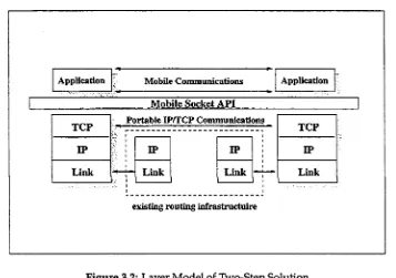
In order to alleviate the above two problems, we propose a two-step solution in
this thesis. The first step is to support portability in network and transport layers. Our
Portable-IP system makes use of existing standards DNS and DHCP and expands the
function of doing IP address allocation and dynamic IP address mapping so as to
support the portability in the IP layer. The second step is to implement mobile com
munication services in the socket layer that lies above the transport layer, but below
the application layer. The enhanced socket code, or Mobile Socket Layer, can bridge the
communication gap while systems are moving and correctly support address map
ping to enable applications and users to use constant IP address or domain name to
identify mobile TCP/IP systems as usual.
We also provide two other models, namely, moving pattern model and cost model to
analyse system performance in a mobile environment. The moving pattern abstracts
the moving characteristics of a mobile system, whereas the cost model provides the
basic standard to evaluate the performance of a mobile system. Our analysis and
simulation give quite encouraging results for our two-step solution.
As a future work, we are going to continue our research in a mobile TCP/IP envi
ronment in the new generation IP protocol — IPv6. Although the mobility has been
taken into account in design of IPv6, its performance and compatibility still need im
A C K A cknow ledgm ent A P Access Point
A P I A pplication Program Interface A R P A dd ress Resolution Protocol
A R P A N E T A dvanced Research Projects A gency N etw ork A S A utono m ou s System
A U T H P A uthentication Protocol
B A S Base Station
B G P Border G atew ay Protocol B O O T P B ootstrap Protocol
C I D R Classless In terdom ain R outing D - D N S D ynam ic D om ain N am e System D H C P D ynam ic H ost C onfiguration Protocol D N S D om ain N am e System
D V R D istance Vector R outing E G P Exterior G atew ay Protocol FA Foreign A gent
F H Fixed H ost F N Foreign N etw ork
F -P S S Foreign Portability S u ppo rt System F R E G P Foreign R egistration Protocol G N G uest N etw ork
G P R S G eneral Packet Radio Service H A H om e A gent
H N H om e N etw ork
H -P S S H om e P ortability S upport System
H R E G P H om e R egistration Protocol
IC M P In ternet C ontrol M essage Protocol
IETF In ternet E ngineering Task Force
IG P Interior G atew ay Protocol
IM H P In ternet M obile H ost Protocol
IP Intern et Protocol
IPX Intern etw ork Packet Exchange
I S D N In tegrated Service Digital N etw ork
IS O International O rganisation for Standardisation
IS P In ternet Service Provider
L A N Local A rea N etw o rk
LLC Logical Link C ontrol
LSR Link State R outing
LSR R Loose Source an d Record Route
M D L M obile D ata L ink
M H M obile H ost
M R M obile R outer
M SL M obility S up p ort Layer
M S R M obile S u p p o rt R outer
N S F N E T N ational Science Foundation N etw ork
O S I O pen System s Interconnection
O S P F O pen Shortest Path First
PH Portable H ost
P O P Point O f Presence
RFC R equest For C om m ent
RIP R oute Inform ation Protocol
RR Resource Record
TLI T ransport Layer Interface TTL Time To Live
U D P U ser D atagram Protocol VP V irtual Port
Acknowledgments v
Abstract
Acronyms *x
1 An Introduction to This Work 1
1.1 Background and M otivation... 1
1.2 Preliminaries of Internet and Its Routing Structure... 4
1.2.1 The TCP/IP Protocols and Internet Structure... 4
1.2.2 IP Addressing and R o u tin g ... 8
1.2.3 Various Ways to Interconnect Internet System s... 14
1.3 Issues of Mobile TCP/IP Communications ... 18
1.3.1 Goal of Mobile Communication ...18
1.3.2 Portable and Mobile C om m unication... 19
1.3.3 Dilemma of Mobile Communication with Current TCP/IP . . . . 20
1.4 Overview of The Present R esearch ... 22
2 Background of Mobile TCP/IP 25 2.1 Functional Layered M o d el...25
2.1.1 Three Types of L a y e r s ... 25
2.1.2 Generic Functional Model of Mobile S y s te m ...27
2.2 Existing Mobile TCP/IP S o lu tio n s... 30
2.2.1 Link Layer Solution ...30
2.2.2 Network Layer S o lu tio n s...33
2.2.3 Transport Layer Solutions...45
3 Two-Step Mobile TCP/IP Solution 49 3.1 IP Forwarding and Its Issues...49
3.2 Basic Idea of Two-step Solution... 51
3.3 Layered Model ... 52
3.4 Identifier: Name and A ddress... 54
3.5 Three invariant conditions for mobile com m unications... 57
3.6 Address M apping... 59
4 Implementation of Portable IP Communications 63
4.1 Introduction... 63
4.2 System F unctions... 64
4.3 System Architecture... 67
4.4 Foreign Registration P rocedure... 69
4.4.1 Important System Parameters... 70
4.4.2 Foreign Registration Protocol — FREGP...72
4.4.3 Authentication Procedure... 79
4.5 Home Registration Procedure...81
4.6 DNS Services For Portable IP System... 82
4.6.1 DNS Query and D atabase... 83
4.6.2 Dynamic Update of D atabase... 85
4.7 Implementation Issues Of Portable IP System ... 89
4.7.1 Additional Functions of H -P SS... 89
4.7.2 Enhancements to Network Library and Socket A P I ... 91
4.8 Simple Performance E stim ations... 95
4.9 Conclusion... 102
5 Implementation of Mobile TCP Communications 103 5.1 Introduction... 103
5.2 Mobile TCP S o lu tio n ...106
5.3 Preliminaries...108
5.3.1 TCP Association and TCP Connection...108
5.3.2 Socket System Calls ...110
5.3.3 The TCP I/O Sem antics...113
5.4 The Continuity of TCP is Mobile Mapping: The Concept and Issues . . . 115
5.4.1 Mobile M a p p in g ...115
5.4.2 Issue 1: Distinguish Old Connection From New Connection . . .119
5.4.3 Issue 2: Keeping the Mobile TCP Socket I/O Semantics the Same 120 5.4.4 Issue 3: Recognition Between Non-mobile and Mobile TCP Ser vices ...121
5.5 Virtual P o rt... 122
5.5.1 Procedure for Connection...123
5.5.2 I/O Semantics...126
5.5.3 Virtual Port P rotocol... 128
5.5.4 The API of M SL... 129
5.6 An E x am p le...131
5.7 Conclusion... 136
6 Performance Studies 137 6.1 Introduction...137
6.2 Cost m o d e ls ...138
6.3 A performance s tu d y ...142
6.3.2 A Simulation environm ent...144
6.3.3 The p a r a m e te r s ...146
6.4 Simulation r e s u lts ... 150
6.5 C o n clu sio n ... 163
7 Mobile File Filtering 165 7.1 In tro d u c tio n ... 165
7.2 Data R eplication...166
7.3 M o tiv a tio n ... 168
7.4 Filtering ... 173
7.5 Implementation I s s u e s ...175
7.5.1 Client-Server M o d e l ...175
7.5.2 In itialisatio n ... 175
7.5.3 Runtime S u p p o r t...176
7.5.4 Sharing S e m a n tic s ...176
7.6 Performance S t u d y ... 178
7.6.1 S im u latio n ...178
7.6.1.1 M o d e l...178
7.6.1.2 Experimental re su lts...180
7.6.2 Exclusion of Unnecessary F i l e s ...182
7.7 C o n clu sio n ... 183
8 Conclusion 185 8.1 C o n clu sio n ... 185
8.2 S u m m ary ... 185
8.3 Future R e s e a rc h ... 187
A N ew and Modified Network/DNS Library Functions 189 A .l G e th o s tb y h a d d r () 189 A. 2 G e ta n s w e r () ... 190
B Simulation Program 193 B. l In tr o d u c tio n ... 193
B.2 Im portant H eader F ile s ... 194
B.2.1 J o b . h ...194
B.2.2 L a n . h ... 198
B.2.3 L i n k . h ... 199
B.2.4 B a c k b o n e , h ...200
B.2.5 M H o s t . h ...201
C Relevant Publications of the Author 203
An Introduction to This Work
1.1 Background and Motivation
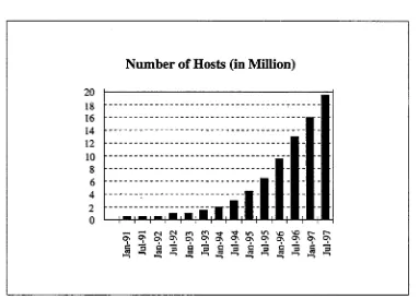
The global Internet is growing very fast. As shown in Figure 1.1 provided by Network
Wizards1, from January 1993 to July 1997 the Internet has grown more than 10 times
in terms of number of hosts. Presently the total number of hosts on the Internet is
more than 20 million. From the survey of NSFNET backbone usages, the top two
applications are web and ftp; these consume 23.9% and 24.2% of the total bandwidth.
It is obvious that more and more people access the Internet as a major information
resource and retrieve data from the network at variety of purposes.
Meanwhile, more and more information services appear over and ride on the
largest worldwide computer network — the Internet, which provide a large quan
tity of information to a variety of people. For example, web browsing is one of the
fast growing application. In January 1993, there were only 130 web servers, and the
number exceeded 650,000 in January 1997. This easy-to-use and powerful informa
tion retrieval means provides for many new applications on the Internet and brings
the Internet into homes and all comers in our modem society. The Internet is no
longer dedicated to any computer researchers and professionals as it used to be in the
beginning stages [40].
Australia has a large Internet user base. According to a recent report from Con-
nect.com.au Pty Ltd, 2.4 million of total 60 million Internet users are in Australia. The
current commercial market has a 11% of monthly growing rate, and in 1998 the
Inter-l a California based communication company, which provides variety of Internet surveys on their web site: http: / /ftp.nw .com /
Number of Hosts (in Million)
[image:16.534.70.453.81.355.2]I
=
M l
Figure 1.1: Number of Hosts (in millions) on The Internet
net traffic will surpass voice traffic. To provide easy, low cost access to the Internet,
more and more local Internet Service Providers (ISPs) arise. That means people can
easily obtain local internet Internet access.
Since the wireless technology is getting mature and portable computer is becom
ing more and more popular, there have been intense interests in portable and mobile
communications2. It is believed that the mobile communication will become a main
trend in telecommunications and data communications. The mobile communication
devices, including portable PC and palm-held specific appliance(e.g. PDA) and cel
lular phone systems, can help users to get rid of the limit of tethered network and
give them more free space to roam. An early statistics reported in [10] shows that
around 74% of all workers are "mobile workers". They spend most of working time
away from their desks. The mobile characteristics of today's computer users have also
boosted the demand for mobile communication products and services.
However, convenient local access to the Internet does not mean access to portable
or mobile services to the Internet. Usually a user subscribes the Internet access
vices from one Internet Service Provider (ISP), which provides the Access Point (AP) of the Internet at certain locations, or called Point of Presence (POP). This user can only access Internet at assigned one or more locations where the ISP has POP there. M ost of ISP companies can only provide several POPs w ithin a small area. A lthough some large ISP companies can provide services to thousands of users, they allow very limited areas where their custom er can obtain access.
Current mobile communications facilities, such as cellular phone system s and wireless networks, can not help to support mobile Internet communications. As is known, digital cellular phone (e.g. GSM) can provide a point-to-point data link con nections. Although the mobile unit itself can obtain a local connection to a local base station, it can establish a link to the fixed Access Point of the Internet, w hich means the user may pay for expansive long-distance mobile connection on top of Internet access fee. Another problem is the speed. Currently GSM cellular phone unit can only provide data rate of 2400bps to 9600bps. Although the forthcoming data service for GSM network, called General Packet Radio Service (GPRS)3, is expected to be im plem ented in next two years and to support data transfer at a rate of up to 100Kbps, the radio communication services are still quite slower than Local Area N etw ork con nection (LAN), ISDN connection and even norm al m odem (33.6Kbps to 56Kbps). The problem w ith wireless LAN is the roaming area, though its speed is high (from sev eral hundred Kbps to 5Mbps). Usually, a wireless LAN covers a very small area, given the limits of its frequency usage and power. Currently, w hen a portable com puter is carried away from home network, the practical way to connect it back to the Internet is to make a connection to home Access Point through dial-up line, either w ired or wireless. Current telecommunications infrastructure is employed to link the portable systems back to their original home AP no m atter how far the users are aw ay from their office or home. Here a dedicated communication link is required for each user. In some cases, the cost of long distance telecommunication link can be prohibitively high and the low utilisation is not desired.
The principal issue w ith mobile communication in the Internet context is how to
allow a host system to obtain a fast local AP, instead of connecting to fixed AP's.
Therefore, this research work focuses on: (i) the analysis and design of mobile proto
cols to provide portable and mobile communications services on the Internet and (ii)
design of a novel mobile file system that can work efficiently in such mobile environ
ment.
For further discussion, we briefly describe some terms we will use regarding mo
bile communications.
• Mobile Host, a TCP/IP-based host which can change its AP to different inter
networks and access network services as a fixed host.
• Home Network, each mobile host has a home network, in which the mobile host
is assigned a permanent IP address which is used by regular TCP/IP protocols
to communicate with each others.
• Foreign Network, in contrast, a network in which mobile hosts temporarily stay
can also be called Guest Network.
1.2 Preliminaries of Internet and Its Routing Structure
1.2.1 The TCP/IP Protocols and Internet Structure
In a further discussion, we differentiate between these two words: the Internet and in
ternet. The former is used to mention the global computer network, whereas the latter
refers to an individual network which employs TCP/IP as internetworking protocol.
The TCP/IP protocol suite is currently the most popular networking standard.
The last decade has seen its success in both academia and industry. The world's
largest network — the Internet provides the most dramatic evidence here. Part of
the reason for its success in computer networking is the original design philosophy
of the TCP/IP protocol suite: namely, the ability to internetwork computer systems
in heterogeneous environments, with computer systems of different sizes, running
different operating systems and supporting different application functions. From its
to-day's Internet, the TCP/IP protocol suite has demonstrated its ability to provide com
munication facilities that allow almost all types of computer systems to exchange data
via TCP/IP protocol networks, or so-called internets. Using TCP/IP technology, all
participating computer systems are interconnected at the network layer level of the
OSI Reference Model; all individual networks are connected by an abstract communi
cation system — the internet that provides a unified, co-operative, interconnection of
networks [5].
TCP, UDP, T-TCP Telnet, FTP,SMTP DNS, NNTP, TFTP
HTTP, DHCP SNMP, PING, etc
IP, ICMP Presentation
Application
Transport
Data Link Network
Physical Session
ARP, PP P, SLIP, etc
m e d ia
Application
Transport
Network
[image:19.534.81.463.243.503.2]Link
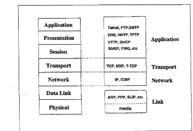
Figure 1.2: ISO/OSI and TCP/IP
As shown in Figure 1.2. The TCP/IP protocol stack has a four-layer model: the
link, network, transport and application layer. Compared to seven-layer ISO/OSI
model, the TCP/IP protocol suite covers the protocol standards from the network
layer up to the application layer in the ISO/OSI reference model, it does not spec
ify protocol standards at the link layer. Protocols above the network layer provide
for end-to-end or process-to-process communications. The network layer protocols
are primarily involved in internetworking systems at different locations and provide
higher layers with services which relate to end-to-end transmissions [72]; they also
underly-ing data link and physical netw ork technologies. For example, the TCP protocol is not aware of where its peer entity is located; the TCP entity merely needs to know the IP address of its peer entity and the IP layer isolates upper layers from the het erogeneous underlying netw ork technologies employed. W hen a TCP entity sends a data segment, it provides the data w ith the IP address of the peer IP system. From the viewpoint of the transport layer, the networks interconnected by the IP protocol are all part of a universal logical internet; every system can reach all others in the inter net. Therefore, the task of internetworking different systems and individual physical networks lies w ithin netw ork layer protocols.
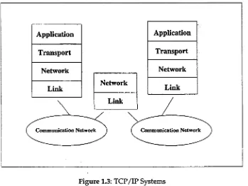
Figure 1.3: TCP/IP Systems
routers or gateways. Actually as OSPF, RIP and BGP should be also p u t in the level according to their functions, because they are all routing protocols. But RIP and BGP use UDP and TCP as transport protocols respectively. Figure 1.3 depicts the protocol layered m odel of internet systems; the computer systems include all layers from the netw ork interface up to the application layer. However, the router has the lowest three layers (end-to-end routing and transmission functions). These are sufficient for a router because it only forwards IP datagram s betw een the netw orks it connects and has no need for higher-level protocols.
network
network
[image:21.534.96.486.271.526.2]network
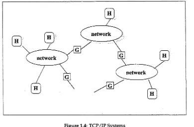
Figure 1.4: TCP/IP Systems
physi-cal networks under a single administration authority form an administration domain,
which is called an autonomous system (AS). Routers within a single AS are called
intra-domain routers, and the routers between distinct ASs are called inter-domain
routers. Different protocols for exchange of routing information are dedicated to these
two types of routers. The basic functions of these two types of routers are, of course,
the same: to route IP datagrams to their destinations between different networks, ei
ther within the same AS or not.
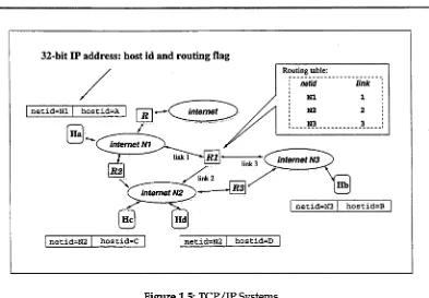
1.2.2 IP Addressing and Routing
The current IP address of IPv4 is 32-bit long, which consists of two parts: netid and
hostid. The IP address is Internet wide meaningful, that means that with the given IP
address a unique host system can be located. According to the IP addressing scheme,
each individual network in an internet obtains an unique netid, then each network
interface4 of a host system has a network-wide unique hostid, with the same netid for
all interfaces attached to the same network.
To reduce the number of logical networks and economise on IP address space,
a single network address may be assigned to several physical networks[60]. In this
case, all sub-networks appear as a single network to the outside world. For routing IP
datagrams correctly to each subnet, some portion of the hostid part of the IP address
is used as a subnet id, so that the netid has more bits than usual. To indicate which
bits identify the subnet, including normal netid bits, a 32-bit subnet mask is used, in
which ones represent the netid and zeroes the hostid.
Given such two-level addressing scheme, the routing function is mainly conducted
by routers, which are the internetworking devices at the IP layer5. The host system
will send out a IP datagram through its Access Point to the local internet. Then the
local routers will find the path to a destination network and forward this datagram to
next router along the path.
4We use the network interface as a component of the IP address instead of individual IP systems to avoid confusion in cases where multiple IP addresses belong to single IP systems. For example, a router connecting two different networks will have a different IP address for each interface.
netid=Nl
32-bit IP address: host id and routing flag
netid=N2 hostid=A
hostid=C internet N1
internet N2 internet
hostid=D
internet N3
Routing table:
[image:23.534.93.486.77.350.2]netid=N3 hostid=B
Figure 1.5: TCP/IP Systems
First, let's look at a schematic example of IP routing. As shown in Figure 1.5, there are three routers that interconnect three internets Ai, A2 and A3. All hosts A, B, C and D are assigned unique IP addresses whose first p art is the netids — N\, A2, Ni and A3 respectively. As indicated, router R\ has three links, and its internal routing table is also given. If H ost Ha sends an IP datagram to H ost Hc, this datagram will be sent to R\, and R\ abstracts the netid from the destination IP address A3/H c. Then, the routing database on this system, called routing table, tells that the destination netw ork A3 is connected by link 3. Therefore, R\ forwards this datagram to netw ork A3 via link 3 so that host Ht> can get the IP datagram. Note that IP routing includes two basic functions. First, the host m ust know how to send a IP datagram to a local router. Second, the router has to be able to figure out the next hop to the destination along a "best" path in terms of variety of measures. In Figure 1.5, there are tw o local routers for host B and C. Furthermore, there are two potential paths from host B to
IP Internal Routing
Actually, each IP system, including the host computer IP entity, will calculate routes
before sending IP datagrams. In the kernel of each IP system, a routing table stores
destination information with corresponding router and local interface details. There
are two kinds of destinations: hosts and networks. When IP sends a datagram, it
searches the routing table to find a matching entry for the destination IP address. If
a host destination is found, the IP will send this datagram via the local interface to
the router indicated in the matching entry. If only the network destination entry is
matched, the datagram is also sent to the router via the interface according to the
routing entry. If no match is found, the datagram is sent via a default routing entry,
if it exists, The worst case is no default entry. In this situation: (i) if the datagram is
generated by the current system, a "host or network unreachable" error message will
be sent to the relevant application, or (ii) if the datagram is received from another sys
tem, an "ICMP host unreachable" error message is sent back to the source system. All
IP entities execute this routing mechanism. Although the routing table is not defined
in the protocol, it plays a very important role in routing datagrams. The table can be
statically modified in two ways: user commands and ICMP redirect messages [57].
When a system starts up, certain commands (such as "route" in UNIX) are used to
store initial routing entries and manipulate the routing table. Also, when any router
finds the current datagram should be sent to another router, it sends an ICMP redirect
message to the source system to inform it of the more-direct route.
Generally, the host system maintains the table only statically. However, routers (or
host systems playing the role of routers) dynamically exchange routing information
and modify their table contents from time to time. The protocols involved here are
divided into two categories, as discussed below.
Intra-domain Routing Protocols
The main purpose of an intra-domain routing protocol is to allow routers in the same
AS to exchange routing information and to update their routing tables dynamically,
time. Furthermore, the routers can use the exchanged information as a basis for find
ing the best route for each datagram, if there are multiple routes to a given destination.
In order to maintain the currency of details regarding network topology, routing infor
mation is periodically exchanged between involved routers. The exchanged informa
tion should be sufficient to ensure that routers can calculate close to optimal routing
for each datagram. Obviously, intra-domain routing protocols focus on these two as
pects. Here the best route does not always mean the shortest path, sometimes the
criterion is cheapest cost or shortest delay time. Generally the types of service defined
in IP can be used to evaluate alternative routes. RIP[50], the most popular routing
protocol in current use, uses UDP as the transport layer protocol to carry pairs of IP
addresses and metrics as routing information. The metric used in RIP is the num
ber of hops from this router to the destination network indicated by the IP address.
After receiving routing information from other routers, the router calculates its own
metric with respect to the destination, chooses the route with the fewest hops as the
best route, and informs the other routers of its routes, too. The routers exchange RIP
messages with neighbouring routers every 30 seconds, or on any change of a route
metric. Routes which have not been updated for more than 3 minutes are deleted.
This method of calculating routes is called Distance Vector Routing(DVR)[39]. The
principle behind it is the Bellman-Ford algorithm for finding the shortest path in a di
rected weighted graph[6]. In some cases, where subnet addresses are applicable, RIP
is not sufficient: it cannot exchange subnet masks between routers. An enhancement
known as RIP-2 [7], was therefore devised. The basic protocol remains the same, but
additional information such as the subnet mask is included in the routing messages.
However, distance vector routing has an inherent weakness of slow convergence. If a
link fails, the routing information will eventually reflect the new topology, but it can
take a long time to reach a new stable state[39].
Due to problems with DVR, a new protocol known as OSPF[55] which uses IP
directly to convey its messages, has been proposed as an alternative to RIP. OSPF is
based on Link State Routing (LSR)[39], whose basic idea is that every router knows
the costs and status of all its links, and can always test the status of any link. The cost
IP protocol. The link costs and status (down or up) are periodically broadcast, and
are also forwarded to all other routers. Therefore, all routers will eventually know
about all other routers and get a complete view of the network topology. Each router
can then build a complete routing table. To route a datagram, Dijkstra's shortest path
algorithm is used to find the cheapest route to the destination. LSR converges faster
than DVR, and fewer routing messages are exchanged between routers. But, if link
costs change and do not affect the shortest path, DVR will not send any message out
whereas LSR will. In practice, LSR is preferred for this reason. Detailed comparisons
of LSR and DVR are given in [39].
Inter-domain Routing Protocols
Unlike intra-domain routing protocols, which always optimise a path according to
the metric or cost, inter-domain routing protocols not only deal with the technical
problems of routing between distinct AS's, but also with routing policies. The best
route from the technological viewpoint may not be satisfactory in terms of policy.
For example, competing companies may reroute their datagrams to avoid traversing
each other's networks for security reasons. Another important issue in relation to
Inter-domain routing protocols has to do with ownership and financing of domains.
If different domains are independently funded, forwarding of datagrams for other
domains (i.e. transit traffic datagrams whose source and destination lie in other do
mains) will consume network resources, with associated financial considerations.
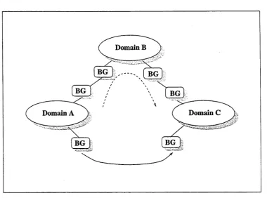
A single AS normally has one or more routers that connect it with other AS's; these
are called border routers. As shown in Figure 1.6, domains A, B and C are intercon
nected by border routers. Between them, an inter-domain routing protocol is used
and global routing information is exchanged. Each domain can use its own policies
to guide its outgoing traffic and to control transit traffic. For example, if domain B is
not willing to forward traffic for domain C, it can advertise the routing information to
other domains' border routers without reporting the link to C. This is called "domain
hiding." All transit traffic through B to C is avoided. Although they may have dif
Domain B
[image:27.534.100.481.89.371.2]Domain C Domain A
Figure 1.6: Border Gateway
version of an inter-dom ain routing protocol in internet is EGP. A new er protocol, BGP (Border Gateway Protocol) [51], has replaced the older EGP. BGP is a distance vec tor protocol; a TCP connection is established betw een neighbouring border routers to carry the routing information.
rep-resented as a supem et w ith the address 194.1.248.0. This supem et address is classless. More detailed explanations here can be found in [45, 46]. This approach is very use ful for some new domains, such as P. R. China which has been assigned only a small num ber of Class B addresses. Additional class C addresses are expected to be assigned subsequently, so CIDR can help with assignment of IP addresses and reduce the size of routing tables for border routers.
1.2.3 Various Ways to Interconnect Internet Systems
The generic structure of an internet is a logical universal netw ork that consists of in dividual netw orks interconnected by intra- or inter-dom ain gateways. Another basic requirem ent is that the interconnection needs data link support. However, the fact that there are different environments and different low-level supporting layers means that particular consideration has to be given to certain aspects of internetworking of TCP/IP-based systems.
Transparent Gateway
a small number of hosts so the routing table in the TG can also be small). The routing
algorithm is simple: the TG forwards to network B all traffic from network A destined
for hosts on network B and vice versa (forwards all datagrams from network B to net
work A, which are sent to such destinations elsewhere except network B). In addition
to separating local traffic, the TG can also reduce the usage of IP network addresses.
The main limitation in using a TG is that network B needs to be reasonably small, be
cause each host IP address occupies an entry in the TG's routing table and searching
a large table is a slow process.
same netid
internet A
n e t i d , * r '
internet B
n e t i d . = K
E Host System
( TG ] Transparent Gateway
Figure 1.7: Transparent Gateway
As an example of the use of a TG, consider a small temporary network that is set
up for an internet-based conference in a building served by an existing local area net
work. A TG could be used to connect the conference room with the existing network.
When the conference is in progress, all local traffic is confined to the small network,
but the hosts can communicate freely with remote hosts. When the conference con
cludes, the temporary network can be disabled. It will then occupy no network ad
dresses and need have no IP addresses reserved for it. Note the distinction between
a TG and a Brouter [39], which take on the roles of both a bridge and a router. The
IP Address Reuse and Internetworking Backbone-partitioned Stubs
Actually a transparent gateway cannot save IP addresses, because each host on both sides needs to be assigned a unique IP address. As we know, IP address space is the m ost limited resource of the Internet where very few unallocated class A and B ad dresses are available. Certain m ethods have been proposed to save IP address space in near term, for instance, by dynamic IP address allocation. IP address translation[49] is another quite practical proposal. The central idea in NAT (Network Address Trans lation) is to concurrently reuse IP addresses in different networks. These IP addresses have only local significance so that no address conflicts occur at a global (Internet- wide) scale.
' internet B internet A
Internet Backbone
internet C
Figure 1.8: Stub Networks
so that only a small fraction of global addresses needs to be shared or reused by all the hosts in the domain. As shown in Figure 1.8, netw ork A and B reside in tw o different domains and hosts H\ and H2 have their own local addresses respectively. The bor
der gateways of network A and B are assigned global addresses and also have some sharable global addresses for their hosts to send or receive datagram s across the bor ders of the two domains. W hen H\ sends a datagram to #2, it uses its local IP address L\ and the global address G2 of H2 as the source and destination addresses respec
tively. The datagram reaches the border gateway BGa/ and BGa chooses an available global address, say G\, tor H\, and makes an entry L\ corresponding to G\ in its trans lation table. BGa then changes the source address of the datagram to G\ and sends it to the internet backbone. Eventually, the datagram reaches BGb, and BGb does the reverse translation from G2 to L2, changing the destination address of the datagram to
L2, so that H2 receives it in dom ain B.
In some cases, two domains m ay belong to the same adm inistration, and they can even use a single local IP address space. Stub dom ains interconnected by an internet backbone are know n as "backbone-partitioned stubs." All such stubs share a common IP netw ork address space, i.e. the host IP addresses are significant am ong all stubs. Most outgoing traffic from these stubs is normally destined for other such stubs. In this case datagram s can even be forwarded w ithout netw ork address translation. For example, internets A and C in Figure 1.8 have a common IP address space, i.e. the local IP addresses of H\ and H3 have the same netid. If H\ w ants to send a datagram to #3, H\ uses L\ and L3 as the source and destination addresses in its datagram . BGa will
find this datagram is destined to a host in the stub connected by BGC/ and BGa encap sulates the whole IP datagram into a special datagram w ith BGa and BGc's global IP addresses and sends it to BGC/ which then picks up the original datagram and sends it to #3.
translation (which is transparent to m ost other systems). Of course, NAT will affect some particular applications that need to know the global IP addresses of hosts in advance.
1.3 Issues of Mobile TCP/IP Communications
In our research work, we focus on TC P/IP internet protocol suite rather than dis cuss and study universal mobile com puting environment. That means two things. First, w hen talking about mobile TC P/IP communications, the scope of netw ork en vironm ent is confined w ithin internet TC P/IP protocol suite, we do not study mobile communications on other netw ork protocols here, such as Novel IPX, Microsoft N et BEUI, though they are also very popular and implemented in some general netw ork operating systems. Second, this research w ork is aimed to study the mobile commu nication mechanisms inside TC P/IP systems, the topics of mobile communications in lower layers (physical and link layer), such as wireless LAN and cellular phone, are out of the scope of this work, given T C P/IP protocol itself does not specify special or dedicated link layer protocols and physical media.
1.3.1 Goal of M obile Communication
internet and work as a normal host system, then to allow users continuously obtain
access to the Internet.
1.3.2 Portable and M obile Communication
For further discussion of potential mobile TCP/IP solutions, we differentiate portable
and mobile communications in an internet environment.
From user's point of view, a mobile system can provide same or similar functions
wherever it goes as if it wras on the home network. From system viewpoint, generally
speaking, a mobile system can dynamically change its attach point to the Internet,
and its TCP/IP communications protocol can work properly in a foreign network. In
all further discussions of mobile TCP/IP communications, we differentiate between
mobile and portable communications modes.
As stated in [73, 29], portable and mobile communications in the Internet con
text have different meanings. The portability means that a host system can change its
attach points hop by hop. At one location, or an internet, provided some standard ser
vices (such as DHCP) are supported, the host systems with built-in portability support
are flexible enough to adjust its system configurations to work in a new environment
that is different from its home environment or previous environment, and such com
munications services provided by TCP/IP can be continuous if and only if the attach
point is fixed in that period. However, a portable system can only support off-line
moving, all communications will be interrupted when the host system migrates from
one place to another.
Mobility requires that a network system be able to provide continuous commu
nications services at all times to the mobile hosts or (units), even when the host is
moving and changing its network attach point. The ideal mobile network commu
nication services for a mobile TCP/IP host are supposed to be able on-line moving,
which is like the mobile communication services provided by a GSM cellular phone
at data link layer. A GSM phone user can keep talking at all times so long as the area
is covered by GSM network. In the Internet context, by the meaning of mobility, a
w ithin the mobile T C P/IP system. Whenever users on such mobile TC P/IP hosts w ant to access a remote service or wherever they are or even moving, the mobility support should be always able to provide access to an Attach Point so as to provide continuous netw ork services.
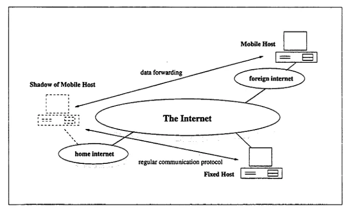
For example, on a personal computer system with mobile T C P/IP support, a user on this system could be able to use telnet to remotely log into a workstation w hen he is on a moving vehicle (Figure 1.9). During the movement, this user m ay traverse several independent netw orks on h is /h e r way and the telnet session is not interrupted. In other w ords, the user can continue to interact w ith the remote system via the same telnet session and is not aw are of system m ovem ent even the actual internet Access Point has been changing all the way. Noting that this is different from using telnet over a GSM modem. The continuous service provided GSM netw ork leaves the Access Point at netw ork layer constant, whereas a truly mobile TC P/IP netw ork system can support the continuous communication services and hide the change of AP.
As show n in Figure 1.9, at the beginning, the user is connected to internet A and the connection w ith the host is through path I; while the user moves to internet B, the connection is not interrupted, it just changes its access point and netw ork path from I to II instead, there always exists only one telnet session between mobile user and the host. Logically, the telnet session seems automatically "handed over" from one attach point to another w ith the geometrical location of the system changing.
1.3.3 Dilemma of M obile Communication with Current TCP/IP
C urrent version of T C P/IP protocol suite, particularly IPv4, was originally designed for fixed host systems. The change of AP's can incur a dilemma to T C P/IP protocols.
internet B
telnet session
The internet
internets „ internet C
Figure 1.9: A user on a mobile PC
Although dynamic routing protocols enable routers to find a best route from source
to destination in a dynamic way, there is no way to find the current location of a
mobile host system and routers only know where a given internet is. An IP address
uniquely belongs to a host system and this host is always supposed to be in that given
internet. If a mobile host still uses its host IP address in a foreign internet, it will not
receive any IP datagrams destined to it: the current routing infrastructure will forward
those IP datagrams to its home network. Although the host system can move within
an internet, given the limitation of covered area of a single internet, the mobility of
current TCP/IP host systems are confined to a small area.
If the mobile host system simply changes its IP address when it migrates to a new
location, it can use the locally assigned IP address to send and receive data in its
current location. However, two problems can be caused by changing IP address. First,
all the protocol connections above the network layer will be lost (this will be discussed
in next chapter), no continuous mobile services are guaranteed. Second, the mobile
host will lose its identifier. The IP address is a very important identifier in the internet
identify local and peer protocol entities. Change of IP address means change of the
important identifier, and the system can not be easily identified. In other words, other
systems can not recognise it as it was in its home network. Moreover, during the
changing of AP's and IP addresses, no communication services can be provided to
application programs, hence the moving is not transparent to network applications.
The NAT protocol and some other address mapping methods are only practical
within the same administrative domain, and some special routers are needed. In sum
mary, to enable a host system change its AP and work in a foreign internet, current
routing and addressing requires it change its IP address; whereas changing IP address
means loss of current connection and identifier. All mobile TCP/IP solutions aim at
solving this dilemma.
1.4 Overview of The Present Research
To achieve mobile communications in TCP/IP internet environment, we have con
sidered various schemes. Some will be discussed in next chapter. The goals of our
research include:
• providing transparent mobile TCP/IP communications services to application
programs, and all mobile operations will be completed without intervention of
users or application programs;
• modeling mobile TCP/IP systems to provide a means for comparing the perfor
mance of mobile TCP/IP systems;
• proposing an important mobile application — mobile file system which is flexi
ble and adaptive to work in different mobile environments;
The major highlights of our research work are as follows:
• Defining functional model to analyse the common structure of a mobile host
system.
• A novel solution of Two-Step mobile TCP to which provide portable commu
applications. This solution is different from existing solutions and can perform
better in any mobile environment.
• Two performance models are built and applied to do system performance anal
ysis: Time Sequential Model and Traffic Model. No related or similar research
work has been reported before.
• A mobile file filtering mechanism is proposed, which is aimed at reducing the
traffic for synchronising duplications of files, based on this mechanism, an adap
tive mobile file system is devised and presented here, which can be easily tai
lored for personal use in a mobile environment.
The structure of this thesis is as follows. In the next chapter we provide a survey
of related research work in mobile TCP/IP and mobile Tile systems. In Chapter 3 we
give the basic scheme of our Two-Step solution. Chapter 4 and 5 present the first and
second step in Two-Step mobile TCP solution. Performance analysis and simulation
work are reported in Chapter 6. Chapter 7 discusses the mobile file system. Chapter
Background of Mobile TCP/IP
2.1 Functional Layered Model
In a netw ork system, the communication protocols or their implementations, which are called entities, can be collected into hierarchical layers. Each layer conducts a set of related functions to support upper layers, while making use of the services provided by underlying layers. We refer to layer as a set of protocols which complete the defined functions. For example, w hen we m ention "netw ork layer", we do not refer to only IP protocol, though it is the core protocol; we are in fact talking about all protocols in the netw ork layer of a particular system, which can include ICMP, special protocols, etc.
2.1.1 Three Types of Layers
To discuss our functional layered m odel for generic mobile netw ork system, the ISO/OSI seven layer m odel is employed as the basic framework. In addition, based on a given layer's behaviour and functionality in a mobile environm ent, we classify it into one of three categories, namely static, portable and mobile.
As given in Figure 2.2, the system can be observed in three different periods: pre-moving: the observed system stays in a fixed location, which can be the home
netw ork or any guest internet. During this period, the system is connected to internetw ork through a fixed AP which is provided by the current internet. moving: the observed system is changing its geographical location from previous lo
continuous services mobile ;v .': •
•>•>« * : • ^N.'jv V ,
Figure 2.1: Static,Portable and Mobile Layer
connection.
post-moving: the observed system arrives at a current location, in which a local new AP is obtained. During this period, the system does not change AP like in pre
moving period.
A single movement consists of these three periods, and the whole observation
time is composed by one or more movements. Here we assume that all protocols will
take identical actions for all movements during one observation, hence we can dis
cuss the protocol behaviour on generic movements rather than particular individual
movements.
Figure 2.1 schematically shows us the functional behaviour of these three types of
protocol layers:
static layer this type of protocol layer can only work in the home network environ ment. It requires a set of fixed system environment variables, which define an
invariable environment. This type of layer is not flexible, it can not function cor
rectly during the moving period or at other locations during post-moving period.
services, which means that the protocol layer can w ork properly at different locations, including the home network. That means the change of AP and w ork ing environment does not affect the portable layer. However, no services are guaranteed during th e moving period.
mobile layer this type of protocol layer can provide continuous services during all kinds of three periods.
A static layer can be portable if its protocol set is enhanced to become capable of w orking in a new environment. Obviously, the mobile layer has portability fea tures, because it can w ork at different locations. Portable layer can also be extended to a mobile layer provided the service-absent gap during moving period can be filled. Therefore, the relationship among these three types of layers is clear: static can be expanded to portable and portable can be enhanced to be mobile.
In the TC P/IP internet protocol suite, almost all existing protocols are designed for fixed host systems, no portable and mobile communication services are taken into account. For example, in an X terminal system, the BOOTP and tftp protocols can only w ork in a pre-configured environment. It requires local server systems to support the necessary system files to boot an X term inal up. Therefore, the application layer of a X terminal is static layer. Moreover, transport and netw ork layers in T C P/IP host systems are static, because TCP, UDP and IP protocols require constant IP address, whereas change of locations or APs requires change of the IP address. Therefore, a norm al TC P/IP system needs some enhancem ents to its protocol layers to support mobile operations. Different methods to enhance the current TC P/IP system lead to different system structure.
2.1.2 Generic Functional M odel of M obile System
In section 2.1.1, we discussed the characteristics of different types of protocol layers in a given layer. Here, we are going to discuss the relationships among these layers in one system.
at current location at new location
Figure 2.2: Layered Model
As we know, a mobile system is supposed to provide a harmonious working envi
ronment to application programs so as to support truly ubiquitous mobile computing.
In contrast, the mobile computing system itself does not imply that all protocol layers
in a mobile system must be mobile and that is not necessary. In the layered model
given in Figure 2.2, the application layer (L,)is the ultimate source and destination of
data being transfered across network systems, which must be able to provide con
tinuous communication services to application programs in turn to support a mobile
network computing environment that is not affected by system movements.In order
to hide all mobile operations and achieve transparent mobility, the communication
gap must be bridged between in layer L\ and Lm. The cooperation of these layers
provide the mobile communications to the ultimate applications.
From Figure 2.2, it is obvious that the mobile communication services or mobil
ity of communication systems is required only at one layer. Assuming that layer L,
supports mobile communications, in other words, it is a mobile layer and provides
w hether L,+ i is a mobile layer or not, it can work in any period given continuous communication services is supported by mobile layer L, and a constant environm ent is m aintained. Consequently, we have that all layers Lj, j > i, can w ork all time. To all layers below layer L„ the basic requirem ent is that these layers m ust be portable layers otherwise the mobility can not be supported at layer L,. A ssum ing that the lowest static layer is L*, k < i. Further assuming k — 1, w hich is the lowest layer in the system. Because L\ is a static protocol layer, as shown in Figure 2.1, it can no t provide communication services outside of the home network. That means layer Li cannot ob tain services from layer L\. In turn any layer Lm, m> 1 can not obtain communication services from the next lower layer, hence the system can not w ork at other location but hom e network. The same situation happens If layer L*, i > k > 1 is a static layer. A lthough all layers Lj, j < k is portable, Lj can not provide communication services and neither all layers form L* up to L(i — 1). Therefore, Layer L,- can not w ork at a new location.
The mobile layer L, has two basic tasks:
• bridging the communication gaps during the moving period. Because portable layers can not provide communication services during moving period, the mo bile layer needs to shield the interruption from upper layer, and continuously support communication requests from u pper layers;
• providing constant communication environment. W hen the mobile system m i grates into a new network, both mobile and portable layers need to change in ternal system param eters to suit the new environment. However, these changes, or mobile operations need to be hidden by the mobile layer so as to provide a constant communication environm ent to these layers above it.
basic promise to im plem ent mobile communications in the global Internet. For exam ple, the variety of Ethernet connections are portable, the user can unplug a Ethernet connector (either RJ45 or BNC) from current connection point and plug it in at a new location, given the Ethernet protocol and connectors are standard in all locations.
2.2 Existing Mobile TCP/IP Solutions
In the TC P/IP protocol suite, to support mobile communications the mobile layer can be placed in all four protocol layers, namely link layer, netw ork layer, transport layer and application layer. Existing solutions can be distinguished based on the prim ary layer on which they provide mobility.
2.2.1 Link Layer Solution
The link layer in T C P/IP protocol suite includes the bottom two layers in ISO/OSI model: physical and data link layers. The protocols in these two layers are mainly related to the physical connection, signal transmission and data framing, sequencing and error detection/correction. The link layer provides a well-defined service inter face to internet (network) layer the data frame transfer channel to a directly connected system.
A lthough internet protocol suite does not specify any particular link layer protocol dedicated for TC P/IP systems, link layer is still a potential place to support mobile communications in an internet environment. As we know, most link layer connec tions, such as Ethernet, can provide a portable communication link to provide mobile communications to TC P/IP protocol layers,
However, the connectivity of the data link is limited in certain areas. For example, any tw o Ethernet segm ent can not be connected over more than five repeaters. To sup port portable and mobile communications in the Internet environment, the netw ork layer or even higher layers will be involved.
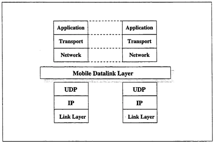
layer makes use of UDP services to make several physical internet netw orks seam lessly integrated into one virtual mobile network.
Application Application
Transport Transport
Network Network
Mobile Datalink Layer
[image:45.534.112.460.151.388.2]Link Layer Link Layer
Figure 2.3: Layered Model of Mobile Data Link
MDL suggests that mobility be transparently supported at the lowest link layer above which all running protocol entities are not conscious of any mobility support. Each M DL-supported netw ork has a Access Point (AP) for mobile hosts to connect to it. Given that MDL is basically designed for wireless host systems, AP is also a bridge to connect the wireless segment to the wired netw ork segment.
W hen a mobile host is in its home network, all data link packets will be sent and received in a norm al way and its home AP acts as a regular bridge. As show n in Figure 2.4, MH2 and A/ / / 3 connect to their home AP (AP\ and AP2, respectively) directly. If the mobile host moves into a guest network, as MH\, its home access point, AP\, and the guest access point, AP2, will cooperate w ith each other to forward data link packets to /fro m the mobile host by encapsulating data link packets into IP datagrams.
these packets locally to MH\. Similarly, all link layer packets sent by MH\ will be
forwarded back to its home network first. Therefore, to all other network hosts MH\
seems stable at its home network.
Internet
Router
M D L
Figure 2.4: Routing of Mobile Data Link
The key issue is the association among MH, home AP and its current registered AP.
These three kinds of component systems form the basis of the mobile data link layer.
The Internet is a data carrier here, which provides connections among AP's. Hence,
the main advantage of MDL is that any network and transport protocols can run over
MDL and obtain transparent mobile communication services, because MDL keeps all
MH s in its home network logically.
However, main concerns with MDL are system performance and compatibility.
Since every forwarded link layer packet will be encapsulated into a UDP packet, the
payload of protocol units is quite low and the use of communication bandwidth is
not efficient as well. Meanwhile all packets to and from a MH away from home are
routed back to its home AP first, this incurs the potential much longer routing and
traffic congestion at APs. Furthermore, there is at least one AP in every participating
network to support link layer packet forwarding. All access points have to know each
2.2.2 Network Layer Solutions
The network layer is mainly responsible for interconnect individual local networks
together and transfer data from source to destination. It deals with end-to-end trans
mission.
Most of recent research work on mobile TCP/IP has been conducted at the net
work layer from where the key problem stems: IP addressing and routing. The mobile
network layer solutions are aimed at supporting mobile IP communications services
to the transport layer and provide a seamless mobile network environment. Given
mobile or portable link layer support, IP is required to provide a continuous data
gram services internally to the transport layer in TCP/IP systems.
There are four major Mobile Host Protocol (MHP) proposals, namely, Sony MHP[73],
Columbia MHP[14,15], IBM MHP [36,37]1 and IMHP[9,34, 35]. The IMHP proposal
was derived from the others, and has now been adopted by IETF as the Internet draft
standard. All of these four MHPs share a common technology that is to provide mo
bility at the network layer and keep the IP addresses of mobile hosts constant to all
the upper layers. Hence, no transport or application protocol entities will be aware
of any mobile operations. All mobile functions are completed at the network layer
and mobility features are hidden from the upper layers. This is a straightforward way
to support mobile hosts given only that the network layer's functionality has to be
enhanced.
Columbia MHP
Columbia MHP was proposed by researchers from the Department of Computer Sci
ence department at Columbia University, which was primarily designed for the cam
pus network environment. The basic idea is that all mobile systems always use con
stant IP addresses in their TCP/IP protocol stacks, and additional routing support is
added to handle the mobile traffic.
The functional layered model is given in Figure 2.5. All the mobile systems will
cooperate with special routing systems to support a mobile network environment.
Application Application
Transport Transport
M o b ile N etw o rk L ayer
Link Link Link Link
routing systems
Figure 2.5: Layered Model of Columbia MHP
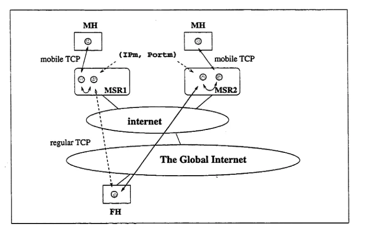
Typically a campus netw ork consists of a set of subnets and a backbone which interconnects all these subnets, as shown in Figure 2.6. At each m obile-supported subnet, there is an ancillary device, called Mobile Support Router2. MSRs are respon sible for routing IP datagram s for mobile hosts to their current subnets. The regular routers and corresponding hosts (either fixed or mobile) send IP datagram s to a near est MSRs first, then MSRs find out the current locations of addressed MHs w ithin the campus environment and forward the traffic to correct destinations.
There are three basic mobile operations among MHs and MSRs:
• MH-to-MSR Handshaking. W hen a mobile host moves into a new subnet, it has to let the local MSR know its presence, then other MSRs can forward packets for the MH;
• MSR-MSR information exchange. W hen a MSR gets a new MH registered w ith it, it sends a message to the MSR which handled the MH before, to enable it forward data to current M H's location. The previous MSR will also inform other MSRs that keep sending data to the MH through it. An MSR also can broadcast requests to all other MSR's to locate a MH;
MSR b
subnet A
Campus Backbone Network
subnet B subnet C
MSR c
Figure 2.6: Routing of Columbia MHP
• Discovery of MSRs. Each MSR should know all IP addresses of MSRs on cam pus. The list of MSRs' IP addresses will be dynamically compiled and dis tributed.
All mobile hosts can be viewed as being located in one mobile subnet. MSRs are the routers to this subnet. If a fixed host needs to talk to an MH at subnet A, as shown in Figure 2.6 it sends packet to local MSR according to the static route to the mobile subnet. Then MSRa locates the current location of the addressed MH w ithin the m o
bile subnet by sending a request message to MSRs in subnet B and C, at the beginning,
MSRc responses the request to MSRA, and the traffic is handled by MSRA and MSRc. W hen MH moves into subnet B, first it registers itself w ith MSRb, and MSRb will in
form MSRc• Then, MSRc sends the redirection inform ation to MSRA and forwards all data destined to the MH to MSRb■ From now on, MSRA and MSRb continue to handle the traffic betw een the fixed host and the MH.