interaction of thin foils with ultra-intense laser fields. White Rose Research Online URL for this paper: http://eprints.whiterose.ac.uk/132197/
Version: Accepted Version
Article:
Duff, Matthew J., Capdessus, R., Sorbo, D. Del et al. (3 more authors) (2018) Modelling the effects of the radiation reaction force on the interaction of thin foils with ultra-intense laser fields. Plasma Physics and Controlled Fusion. 064006. pp. 1-13. ISSN 1361-6587 https://doi.org/10.1088/1361-6587/aab97d
[email protected] https://eprints.whiterose.ac.uk/ Reuse
Items deposited in White Rose Research Online are protected by copyright, with all rights reserved unless indicated otherwise. They may be downloaded and/or printed for private study, or other acts as permitted by national copyright laws. The publisher or other rights holders may allow further reproduction and re-use of the full text version. This is indicated by the licence information on the White Rose Research Online record for the item.
Takedown
If you consider content in White Rose Research Online to be in breach of UK law, please notify us by
on the interaction of thin foils with ultra-intense
laser fields
M J Duff1, R Capdessus1, D Del Sorbo2, C P Ridgers2, M King1 and P McKenna1
1SUPA, Department of Physics, University of Strathclyde, Glasgow, G4 0NG, UK
2York Plasma Institute, Department of Physics, University of York, YO10 5DQ, UK
E-mail: [email protected], [email protected], [email protected]
October 2017
Abstract. The effects of the radiation reaction (RR) force on thin foils undergoing radiation pressure acceleration (RPA) are investigated. Using QED-particle-in-cell simulations, the influence of the RR force on the collective electron dynamics within the target can be examined. The magnitude of the RR force is found to be strongly dependent on the target thickness, leading to effects which can be observed on a macroscopic scale, such as changes to the distribution of the emitted radiation and the target dynamics. This suggests that such parameters may be controlled in experiments at multi-PW laser facilities. In addition, the effects of the RR force are characterized in terms of an average radiation emission angle. We present an analytical model which, for the first time, describes the effect of the RR force on the collective electron dynamics within the ‘light-sail’ regime of RPA. The predictions of this model can be tested in future experiments with ultra-high intensity lasers interacting with solid targets.
Keywords: Radiation reaction force; Radiation pressure acceleration; Relativistic laser-plasma interactions
Submitted to: Plasma Phys. Control. Fusion
1. Introduction
The multi-petawatt (PW) laser facilities currently under construction, such as the Ex-treme Light Infrastructure (ELI) [1] and APOLLON [2], will produce peak laser intensi-ties exceeding 1023 Wcm−2. It is expected that this will result in the acceleration of ions
[6]. The transfer of momentum to the target as the laser reflects off its front surface can accelerate the target ions to high energies in quasi-monoenergetic bunches. The potential applications of the resulting beams of energetic ions include oncology [7] and the fast ignition approach to inertial confinement fusion [8, 9]. The effectiveness of the RPA mechanism is highest for targets which are just above the critical density (at which the plasma frequency is equal to the laser frequency) and is greatly reduced if the target undergoes relativistic self induced transparency (RSIT; caused by a reduction in the plasma frequency to below the laser frequency, due to the relativistic increase in the mass of the oscillating target electrons). Not only does the resultant laser propagation into the target volume reduce the radiation pressure on the surface, but it also heats the electrons in the bulk of the target, which enhances other acceleration mechanisms [10, 11, 12, 13]. The maximum ion energies which can be achieved using multi-PW laser systems may however be restricted by the onset of the radiation reaction (RR) force and QED effects (such as electron positron pair-production and stochastic photon emission), which become important at laser intensities exceeding 1022 Wcm−2 [14].
RR is the process by which electrons accelerating in ultra-intense laser fields expe-rience a recoil force, due to momentum loss during radiation emission [15, 16, 17, 18]. This classical view of RR as a frictional force acting on the electrons has recently been demonstrated experimentally [19, 20, 21]. Above intensities of the order of 1022 Wcm−2
however, RR cannot be described classically, but instead must be described in the con-text of strong field QED. The importance of these QED effects are parameterized by
χe, the ratio of the electric field strength experienced by the electron in its rest frame, to the QED field limit [22]. Quantum processes become important for χe & 0.1, with prolific pair production occuring at χe ≃ 1. This parameter is strongly dependent on the interaction geometry; electrons which counter-propagate against a laser pulse experience Doppler-upshifted fields, leading to a higherχe and stronger RR. Radiation reaction has important consequences for experiments at future multi-PW laser facilities, as it not only affects the target electron dynamics, but also impacts on ion acceleration through modification to the self-consistent charge-separation fields within the plasma [23, 24]. The effects of RR on ion acceleration in the light-sail (LS) regime of RPA [25, 26] have been investigated in references [27, 28, 29, 30]. These studies indicate that it is the electrons which counter-propagate with respect to the laser pulse (and which are therefore subjected to the highestχe values) which experience significant RR effects in this regime.
The remainder of the article is organized as follows. A brief overview of the un-derpinning theory of ultra-intense laser plasma interactions is presented in section 2. An analytical model which describes LS acceleration in the presence of the RR force is introduced in section 3. In section 4, a brief overview of the theory underpinning QED-PIC code simulations of high field interactions is provided, including the imple-mentation of RR effects. The results of a series of 1D(3P) QED-PIC code simulations, investigating the radiation distribution, energy partition and target dynamics in the LS regime, are discussed in section 5. The simulation results are compared with predictions of the analytical model. The article concludes with a brief discussion of how the model predictions could be tested experimentally at multi-PW laser facilities.
2. Underpinning theory
2.1. Electron motion in strong fields
Electrons oscillating in ultra-intense laser fields can acquire relativistic velocities. The electron motion becomes relativistic when the dimensionless laser vector potentiala0 >1
[31], where:
a0 =
eE mecωL
, (1)
eandmeare the electron charge and mass, respectively,E is the electric field strength,c is the speed of light andωLis the laser frequency. Accelerating electrons in ultra-intense laser fields produce photons of radiation, which carry away momentum. This loss of momentum can be interpreted in the classical framework as a frictional force acting on the electrons, which is the RR force. The equation of motion for a radiating electron therefore depends on both the force from the external laser fields and the back-reaction force exerted due to the emission of high energy radiation from the relativistic electrons. Fora0 ≫1, the photon formation length is small, in which case the emitted radiation is
synchrotron-like. The spectrum can be described by the quantum synchrotron spectrum, with the radiation emitted into a narrow cone along the direction of electron momentum [32].
Provided that the magnitude of the RR force acting on the electron in its rest frame is much weaker than that of the Lorentz force, then the Landau-Lifshitz (LL) [16] model, which has been shown to be consistent with the classical limit of strong-field QED [33, 34], is sufficient to describe the electron dynamics. Treating RR as a frictional force, the LL equation can be expressed in vectorial form, as:
d
dtpe=FL,e+Frad (2)
We can write the electron radiated power in terms of the Lorentz force and a characteristic angle, such that:
Pγ =
τrγe2
me
F2L,e1−βe2cos2ψg(χe). (3)
Here, τr = e 2
6πǫ0mec3 ≃6.2×10
−24 s is the classical radiation time scale, corresponding to
2/3 times the light crossing time of the classical electron radius, and γe = (1−βe2)−1/2 is the Lorentz factor. The characteristic angle, ψ, which appears in equation (3) is the angle between the perpendicular component of the Lorentz force and the electron mo-tion. χe is a Lorentz invariant parameter which describes the importance of quantum effects. These effects lead to an over-estimation of the electron radiated power in the semi-classical regime, and are accounted for through the introduction of a scaling factor,
g(χe). Further details are provided in the Appendix. The quantum parameter is defined as follows:
χe=
γe
eEsh q
F2L,e−(FL,e·β)2 (4)
where, Esh is the Schwinger limit for electric field strength, such that Esh = m2ec3/e~ [22].
It is convenient to re-write the Lorentz force term in terms of the laser a0, which is
proportional to the intensity, and in terms of a characteristic angle,θ, which represents the projection of the electron velocity along the direction of laser propagation. We assume that the laser electric field has a larger magnitude than that of the charge separation field, such that Ey ≫ Ex. This leads to the following expression for the Lorentz force:
F2L,e =a20(mecωL)2(1−βecosθ)2. (5)
We stress that the angles θ and ψ are not independent, as both depend on the electron momentum. Assuming that Ez is negligible, the relation between the angles is written:
cosψ = αcos√θ+ sinθ
1 +α2 . (6)
where α = Ex/Ey, such that when Ey ≫ Ex, ψ ≃ π2 −θ. Using these equations, it is now possible to evaluate the force exerted on an electron due to photon emission:
Frad =g(χe)G(θ)βeτrωLγe2a20mecωL. (7)
We have introduced a function, G(θ), into equation (7) which gathers the terms relating to the angular dependence of the electron radiated power. This function is written explicitly below.
G(θ) = (1−cosθ)
2
1 +α2
3. Modelling the radiation losses
Radiation reaction effects are typically overlooked in the LS regime of radiation pressure acceleration; since the targets can acquire relativistic velocities, the laser fields are strongly Doppler shifted, reducing the intensity which arrives at the target in its reference frame. This effect has been observed in a recent study by Del Sorboet al[35], in which quantum effects are found to be quenched due to the high target velocity which can be obtained in the LS regime. That study used circularly polarized laser pulses, in which case electron heating via the oscillating component of the ponderomotive force is suppressed, and the targets undergo highly efficient acceleration. By contrast, here we consider linear polarization such that the electron heating effects are still present, allowing RR to influence the collective electron dynamics.
Whilst RR effects are negligible when the target acts as a perfectly reflecting mirror, as previously described, it is not the case for this study, where the target can instead absorb laser energy. Ionization of the target front surface produces a plasma, in which the electrons gain energy from the laser, and subsequently experience radiative cooling as they oscillate in the strong electromagnetic fields. These radiating electrons are found to be localized to within the target charge depletion zone. The cooling of electrons through the RR force changes the dynamics of the self-consistent fields within the target, therefore impacting the ion dynamics [36, 28, 29]. As the target continues to absorb laser energy it will expand, resulting in a decrease in the electron density. When the target areal density, ξ, reaches the same order of magnitude as the laser a0, it can
undergo relativistic self induced transparency (RSIT), at which point the electrons in the bulk of the target are strongly heated and the efficiency of target acceleration is greatly reduced. The normalized areal density for a target of thickness, l, and with a critical density nc, is given byξ =πne
nc l
λL[26, 25].
We have outlined various scenarios in which the RR force can have a significant effect on the collective electron dynamics within the LS regime. In order to model these effects, we present a modification to an existing LS model, which is detailed in Macchi
et al [25].
An intense laser pulse interating with a solid target can be reflected, absorbed, or transmitted (if the target undergoes transparency during the interaction). The relative probabilities of these outcomes are related as follows:
R+T +A = 1 (9)
function of absorption (R= 1− A), leading to the following equation of motion:
d
dt(γtβt) = I
ρlc2(2− A)
1−βt 1 +βt
. (10)
The absorption term is obtained by normalizing the intensity of radiation emitted by the electrons, up until the target undergoes transparency (at time t = ttr), to the laser intensity
A ≈ Nrad Rttr
0 hPγidt
Rttr 0 ILdt
(11)
where,
hPγi ≡ R
R3fePγdpe
ne
, (12)
is the total radiated power of the electrons of the plasma, such that ne ≡ RR3fedpe defines the electron number density.
In order to evaluate the total radiated power, we require knowledge of the radiating electron distribution function. Assuming that electrons are strongly heated by the oscillating component of the ponderomotive force, which is particularly true in our study due to the use of linear laser polarization, the electron distribution is modelled using an isotropic Maxwell Juttner distribution such that
fe(γe) = Nexp
−(γeΘ−1)
(13)
where, N = ne 4πm3
ec3K2(1/Θ)Θ is the normalization coefficient and Θ = Te
mec2. Since a0 ≫1 we may assume Te∼a0mec2 which yields
hPγi= 12a40G(θ)g(χe)ωLτrmec2ωL. (14) We have used that K2(1/Θ) ≃ 2θ2 for Θ ≫ 1 and assumed βe ≃ 1 in the functions G(θ) and g(χe). Comparison with electron spectra obtained from simulations, however, indicates that whilst the Maxwell Juttner distribution is a reasonable approximation (further details are provided in the Appendix), it over-estimates the electron temperature. To account for this, we introduce a scaling function analogous to that described in reference [37], which describes the cooling of the electrons.
S(θ, φ) = 1 +ωLτrG(θ)a30
Z φ
0
ϕ2(φ′)dφ′ (15)
where ϕ is a function describing the pulse shape and φ =kx−ωLt is the phase. This scaling is applied in the evaluation of equation (11).
described in this picture is similar to the physics of the radiating electrons in the LS regime. Figure 4 further illustrates the similarities, and demonstrates how, in this study, radiation emission is localized to the target depletion zone, i.e. the distance over which the charge separation field extends.
Liseykinaet al [38] derive an expression for the number of radiating electrons in the hole boring regime, under the assumption that a0nc/n0 >1, with nc =
p
γeǫ0meω2L/e2 representing the critical density. This leads to an expression for Nrad which is independent of the target thickness. This is not the case for the simulations presented here; instead we derive an expression forNradwhich is dependent on the size of the charge depletion zone, and therefore on the overall target thickness. Following the method outlined in reference [38], we balance the electrostatic pressure with laser radiation pressure, in this case eliminating the skin depth from the resulting equations to derive the following expression:
Nrad =
a2 0 π nc n0 1
rcd
1
4+ 1 4
n
0dωL
ncca0
21/2 −1
2
. (16)
Here, rc =e2/mec2 is the classical electron radius,n0 is the initial electron density
in the target skin depth, and d is the size of the charge depletion zone, indicating the region where radiation production is localized. In the case where a0nc/n0 > 1, the
scaling derived in reference [38] is obtained, namely
Nrad =
a0
rcλL
. (17)
Equation (17) assumes that the target, in the hole boring regime, is infinitely thick. A return current can therefore be drawn to cancel the charge separation field, allowing electrons to return to the charge depletion zone and produce radiation as they counter-propagate with respect to the laser. In the LS regime however, the targets are significantly thinner, meaning that a smaller return current is drawn and therefore the number of radiating electrons is reduced. The size of the depletion zone clearly impacts the number of radiating electrons. Equation (16) accounts for this target thickness dependence, predicting a smaller number of radiating electrons compared to (17) in the range of thickness considered here.
Finally, using equation (17), an estimate of the absorption can be obtained:
A ≈ a
3 0
rcλL
. (18)
In our case however, the absorption remains a more complicated function of a0,
obtained by substituting equations (12) and (16) into (11). The absorption, equivalent to the photon conversion efficiency, calculated by this model is plotted in figure 5. It can be seen that there is good qualitative agreement with the values calculated from the simulations.
phase, φ, and integrate up to the time of transparency, at which point the efficiency of the RPA will be greatly reduced. This leads to an expression for the target velocity of the following form:
βt=
(ǫ(φ)−a(φ) + 1)2−1
(ǫ(φ)−a(φ) + 1)2+ 1. (19)
where ǫ(φ) = 2F(φ)/ρlc2 is the normalized laser fluence, such that F(φ) = Rφ
0 I(φ′)dφ′
and a(φ = φtr) is the radiative correction evaluated at the time at which the target undergoes transparency, given by
a(φ=φtr) = 12G(θ)g(χe)ω
2
Lτrmec2 Rφtr
0 a50(φ′)dφ′
rcλLρlc2
. (20)
When the conversion of laser energy to photons is negligible, i.e. for a model which neglects RR, the expression for the target velocity derived in reference [25] is recovered.
4. Numerical approach
4.1. Numerical model
PIC codes offer a good description of collisionless plasmas where collective effects dom-inate. Within the plasma, the emission of synchrotron radiation from relativistic elec-trons is handled stochastically, using a Monte-Carlo algorithm to compute the proba-bility of photon emission. The synchrotron photons correspond to high-frequency radi-ation, in which case the interaction of photons, electrons and positrons is handled using the method of Baier and Katkov [40]. The emitted photons carry away momentum, which is subtracted from the classical momentum of the radiating particle. The parti-cles therefore follow a classical trajectory between photon emission events. Stochastic effects (described in detail in the Appendix) are accounted for in this way, rather than through the damping of the RR term in the LL equation.
In the simulations presented in this paper, we isolate effects which arise purely due to RR by running simulations with and without RR. In the cases with RR off, photons of synchrotron radiation are still produced, however there is no subsequent recoil force on the electrons. This situation is unphysical, and is only used as a tool to extract the physics which arises due to purely RR effects.
4.2. Simulation parameters
We present the results of 1D(3P) simulations using the fully relativistic EPOCH QED PIC code [41]. 1D simulations have been used to scan over a wide range of parameters with high resolution. We investigate the interaction of solid density (777nc, which is also initially relativistically overdense, such that ne > γnc) aluminium targets, in a charge state of 13+, with an ultra-intense Gaussian laser pulse with a peak intensity of 2×10²³
Wcm−2 (corresponding to a peak a
a FWHM pulse duration of 60 fs. Initially the simulations have 1000 particles-per-cell and a spatial resolution of 2 nm, leading to a high spatial convergence.
At the intensity considered, the RR force will play a role in the electron dynamics whilst higher order QED effects such as pair-production can be neglected [42]. The quantum parameter,χe, is small in this regime however we re-iterate that the stochastic effects associated with a small but non-negligible value of χe are accounted for in the Monte-Carlo algorithm for photon emission.
The targets are varied in thickness in the rangel=50-400 nm, such that during the interaction they are accelerated in a LS like regime. In order to be rigorous, we refer in this paper to a LS like regime, as some of the assumptions used in the derivation of the LS model presented in reference [25] do not hold. For example, in this case the target does not act like a perfect mirror as some of the laser energy is absorbed, and the RR force will change the dynamics of the system.
We consider only linear polarization here, in contrast to the recent study by Del Sorbo et al [35]. This choice accentuates the RR effects, due to an enhancement in the electron heating through the oscillating component of the laser ponderomotive force. The enhancement to RR effects in linear polarization has been reported in references [6, 29]. In addition, the use of linearly polarized light makes this study more relevant for the guidance of future experiments. The first experiments on ELI-NP, for example, are likely to use linear polarization as only one of the two 10 PW beams will be initially commissioned with control over the laser polarization [43].
5. Numerical simulations results
5.1. Distribution of emitted radiation
The effect of the RR force acting on the collective electron dynamics can be quantified through changes in the distribution of the emitted radiation from the target. In order to characterize these changes, we define a first average emission angle by taking the ratio of the electron transverse to longitudinal momentum and averaging over the electron distribution function, as follows:
hθi= R
R3θfedpe R
R3fedpe
(21)
θ = arctan (pe,y/pe,x). (22)
Here, the output angles are in the range hθi ∈ [−π, π], with π/2 the direction perpendicular to target normal. In this section, radiation emitted in the ‘backwards’ direction is taken to mean emission at angles | hθi |∈[π/2, π].
0 0.1 0.2 0.3 0.4
l/
L
50 60 70 80 90 100 110
RR on
RR off
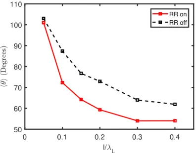
Figure 1. Average emission angle hθi as a function of target thickness, calculated at the time of maximum synchrotron emission. The solid red line represents the case with RR on, whilst the dashed black line is the case with RR off.
with an opening angle equal to 1/γe. Therefore the direction of an emitted photon is assumed to be the same as that of the emitting electron, correlating the electron and photon average emission angle and allowing these to be used interchangably.
Figure 1 shows the first average emission angle as a function of target thickness, with and without RR. We remind the reader that without RR, photons of synchrotron radiation are still produced, however their momentum is not accounted for and the electron does not experience a recoil force. This case is included only to give an indication of how the RR force changes the collective electron dynamics. Each point in figure 1 is calculated at the time of maximum synchrotron emission for the corresponding target thickness.
Figure 1 shows a decrease in the average emission angle for the case with RR on, caused by radiative cooling and reflection of the electron population which moves against the laser. As discussed in section 3, this electron population is formed as the target front surface ionizes, producing an expanding plasma. The plasma electrons which propagate in the backwards direction then experience the strongest RR effects due to a Doppler upshift of the laser fields, to the point where they can be reflected by the pulse. These electrons can no longer contribute radiation in the backwards direction, therefore causing a decrease in the average emission angle.
the charge separation fields within the plasma, leading to a reduction in the average emission angle with RR on. For these target thicknesses, there is a higher number of radiating electrons, meaning that more will be cooled and reflected by the laser. These electrons bunch up at the laser plasma interface, producing a region of high electron density and therefore increasing the strength of the charge separation fields within the target. This allows the electrons to acquire a larger longitudinal momentum and therefore, as px increases, the average emission angle decreases. This increase in the magnitude of the charge separation fields only occurs with RR on, since it is related to the cooling and reflection of the electrons by radiation emission. The number of radiating electrons is maximized for a target thickness of 200 nm, in agreement with the Nrad calculated using equation (16). This is also the thickness which corresponds to the largest reduction in average emission angle, with and without RR. For the thickest targets however, the areal density is sufficiently high that the laser drives a strong electrostatic shock. The electrons therefore experience shock driven acceleration, leading to weaker RR effects.
The reduction in the average emission angle can be related to a change in the target velocity. Since the radiation is more forwards directed when RR effects are included, the emission of synchrotron photons will induce a larger recoil force on the target compared to the case with RR off. This occurs due to the smaller average emission angle, as there will be a larger component of the RR force along the direction of target propagation since this varies with the cosine of the emission angle.
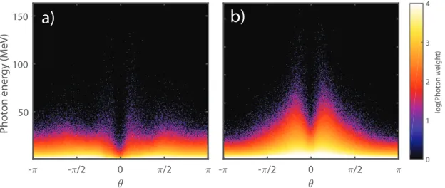
An important point to consider here is that the model presented in section 3 applies only to targets where the electrons have radiated the majority of their energy before the target undergoes transparency, i.e. trad < ttr. If this is not the case, then the effects of the RR force on the collective electron dynamics are washed out by the onset of transparency and RR effects are negligible. For the 50 nm case, this condition is not satisfied, and instead the maximum synchrotron emission time occurs after transparency. This explains why the average emission angle is> π/2, there are no significant RR effects to reflect the electrons and reduce the radiation emission in the backwards direction. We point out that whilst the average emission angle can be obtained from the photon spectra, and could potentially be measured in future experiments, that the condition
trad < ttr may be necessary before macroscopic RR effects can be observed.
The analysis of the emitted radiation has thus far shown that radiative cooling of
- - /2 0 /2
50 100 150
Photon energy (MeV)
0 1 2 3 4
log(Photon weight)
- - /2 0 /2
a)
b)
Figure 2. Photon angular distributions for (a) 50 nm target and (b) 200 nm target. These distributions are compared at the time of maximum synchrotron emission, corresponding to timest= 13TL andt= 31TL respectively.
electrons leads to a decrease in the average emission angle of the emitted radiation, an effect which can be observed in the photon distribution. We can develop this analysis further by defining a second average emission angle, δθ, which quantifies differences in the distributions with and without RR. This angle is defined as follows:
δθ= arctanhδpyi hδpxi
(23)
where,
hδpxi ≡px,RR on−px,RR of f = t Z
0
Frad,x(t′)dt′ (24)
hδpyi ≡py,RR on−py,RR of f = t Z
0
Frad,y(t′)dt′ (25)
leading to:
δθ= arctan Rt
0 a20(t′)βe,yG(θ)dt ′
Rt
0 a 2
0(t′)βe,xG(θ)dt ′
. (26)
0 0.1 0.2 0.3 0.4
l/ L 50
60 70 80 90 100 110
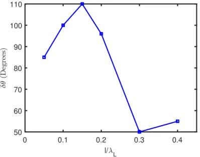
Figure 3. Variation of the second average emission angle, δθ, with target thickness. This angle provides information on the partition of the RR force into the longitudinal and transverse directions.
amplitude of the contraction using equation (15). For the target parameters used in this study, the reduction in phase space volume is approximately a factor of 1.5.
An interesting feature of this second emission angle is that it is deterministic rather than stochastic. This can be seen in equation (26), where δθ is seen to depend on the integration over time of the laser intensity and the target velocity. It therefore maps out the history of the RR force during the interaction, rather than being a stochastic variable. It is found that δθ is the average emission angle which should be used to define G(θ), since this angle quantifies the differences in the electron populations with and without RR. It is implied that after averaging over the distribution, hθi →δθ.
The variation of the second average emission angle with target thickness is plotted in figure 3. For targets between 50-200 nm thick, we can see that the large values of the average emission angle (δθ & π/2) implies that δpy ≫ δpx and so there is more contraction of phase space in the transverse direction compared to that of the longitudinal. This difference again is an effect of the onset of transparency; as the targets undergo RSIT, an expanding plasma is produced in which the electrons are heated as they expand in the longitudinal and transverse directions. The comparatively thicker targets are not subject to this effect, and so the radiative cooling predominantly occurs for electrons returning to the charge depletion zone (i.e. a longitudinal effect).
5.2. Energy partition and target dynamics
The dynamics of the target as it accelerates in the LS like regime are investigated in more detail in this section. Futher details of this regime are provided in figure 4. Radiation pressure from the laser pushes electrons in the target into the skin depth, the distance over which the laser fields evanescently decay within an overdense target. This forms a compressed layer of electrons, which is then pushed into the bulk of the target by radiation pressure. The charge imbalance as the electrons accelerate away from the ions produces a charge separation field, which subsequently accelerates the ions. The region of high electron density, and the resulting charge separation field, are plotted from a sample simulation in figure 4. As discussed in section 2, it is the counter-propagating electrons which experience the strongest RR; this effect is further illustrated in figure 4, where the spatial distribution of the electron radiated power is overlaid with the spatial distribution of the charge separation field. This figure indicates that radiation production is localized to within the charge separation field, enabling calculation of the number of radiating electrons using our analytical model.
The conversion efficiency of laser energy into plasma species has been investigated
50 52 54 56 58 60
X/
L
0 1 2 3 4 5
0.5*d
x
P
0 5 10 15 20 25
(t) (%)
lrad = 1.92 m
as a function of target thickness, with and without RR, in figure 5. We compare our results to a similar 1D(3P) simulation study by Tamburiniet al[29], in which the energy partition was investigated as a function of time for a fixed target thickness. Similar laser and target parameters were used in the aforementioned study (I = 2.33×10²³ Wcm−2
and ne= 100nc).
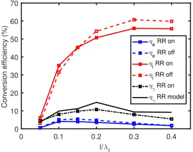
A key feature of figure 5 is that the electron conversion efficiency remains relatively unchanged, with and without RR. Since RR causes the electrons to radiatively cool, it would be expected that the electron conversion efficiency would subsequently decrease. This effect can again be related back to the counter-propagating electrons, which are cooled and reflected by the laser and subsequently trapped at the laser plasma interface. Here, they can continue absorbing laser energy, approximately balancing the radiation losses.
Figure 5 shows that the ion conversion efficiency in ultra-intense laser solid
0 0.1 0.2 0.3 0.4
l/ L 0
10 20 30 40 50 60 70
Conversion efficiency (%)
e RR on
e RR off
i RR on
i RR off RR on
RR model
Figure 5. Conversion efficiency of laser energy to electrons (blue), ions (red) and photons (black). Dashed lines represent the cases with RR off, whilst solid lines indicate the cases with RR on. The photon conversion efficiency with RR off is omitted, as this does not conserve energy and therefore has no influence on the energy partition. The solid black line refers to the absorption calculated using our model, whilst the dot-dash black line is the photon conversion efficiency measured from simulations.
reduction in the ion conversion efficiency occurs for the case with RR on. This is because more of the laser energy is converted into photons of synchrotron radiation. Since the electron conversion efficiency remains the same with and without RR, differences in the energy partition are a result of laser energy being coupled preferably into radiation as opposed to ions. With RR off, we do not consider the laser energy coupled into radiation, since this case does not conserve energy. The ion conversion efficiency is therefore higher as laser energy can only be shared between the ions and electrons, and as discussed earlier, the electron conversion efficiency is relatively unchanged with and without RR.
The photon conversion efficiency is shown in figure 5 for the case with RR on (dot-dashed black line). The magnitude of the photon conversion efficiency, as calculated from the simulations, is of the of order 10% and therefore in agreement with the results reported in reference [29]. The black solid line in figure 5 represents the photon conversion efficiency, calculated using our analytical model. There is good agreement with the simulation results, showing the same peak in photon conversion efficiency for a target thickness of 200 nm. This is the same case for which the number of radiating electrons is maximized, as predicted using our analytical model, equation (16). This model however tends to overestimate the photon conversion efficiency, as it does not account for transparency of the target and therefore the ‘loss’ of laser energy transmitted through the target.
Finally, we can use the simulations to verify the predictions of the target velocity from our analytical model. The target velocity is obtained from simulations by tracking the position of maximum electron density as a function of time. This maximum density surface indicates the interface at which RPA occurs.
0 0.1 0.2 0.3 0.4 l/
L
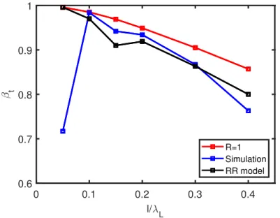
0.6 0.7 0.8 0.9 1
t
R=1
Simulation
RR model
Figure 6. A plot comparing the target velocity predicted by our model (solid black line) to measurements from simulations (solid blue line) and an existing LS model (red solid line) which assumes the reflectivity of the target,R, is unity.
which complicate the dynamics of the RPA process. For this reason, we measure the target velocity at the end of the simulation, when it has reached a constant value.
For the cases where the radiated power is high, we can obtain radiative corrections which are larger than the normalized fluence. This arises from the assumption that the electron temperature scales according to the ponderomotive potential. In order to correct for this, the radiative correction is scaled by the ratio Te(φrad)/Te(φ0). Here,
Te(φrad) is the electron temperature at the time of maximum synchrotron emission, and
Te(φ0) is the electron temperature associated with the laser a0 measured at this same
time.
From figure 6, we see relatively good agreement between the velocity calculated using our RR model and the simulations. The agreement is better for thicker targets (ξ > a0), where transparency is not as important in the dynamics. As our model does not
5.3. Experimental prospectives
We have presented a 1D analytical model which describes the effects of the RR force on collective electron dynamics within the LS regime. This enables calculation of the laser energy absorption and the velocity of the target as it undergoes radiation pressure acceleration. In deriving this model, we assume that the charge separation field, whilst not negligible, is weaker than the laser field, although it enhances the production of high energy radiation [45]. The role of the charge separation field is an important aspect of the model and one which could be investigated experimentally (for example, via measurements of ion acceleration).
The model can also be used to make qualitative predictions about the distribution of the emitted radiation, which could be tested in future experiments. A key feature, described in section 5.1, is that the angular emission decreases as a function of target thickness and that the rate of decrease changes due to RR. Experiments at multi-PW facilities could test this dependency (for example, by making angularly-resolved measurements of radiation emission, using arrays of scintillators, X-ray film or ImagePlate detector). Cyrogenic hydrogen targets could be used to reduce Bremsstrahlung emission, as discussed for example in references [43, 45].
Finally, in section 5.1 it is shown that the distribution of emitted radiation changes depending on the time at which relativistic transparency occurs during the interaction. In particular, we note the disappearance of lobe-like structures from the photon distribution if the interaction is transparency dominated. If this effect is experimentally verified, it may act as a diagnostic for the onset of the transparency process.
6. Conclusions
Building upon the work presented in references [28, 29], we have further demonstrated that semi-classical RR effects can be significant in the LS regime of RPA if the absorption of laser energy by target electrons is considered, rather than assuming the target acts as a perfect relativistic mirror, i.e when a0 > ξ. By defining an average emission
angle, the magnitude of the RR force effects on the collective electron dynamics can be characterized. We show that the amplitude of the RR force is determined by the target thickness, and investigate this effect over a wider range of target parameters than those presented in reference [24].
We have also outlined aspects of the model which can be experimentally tested at multi-PW laser facilities. This study indicates that the distribution of radiation from thin foils in ultra-intense laser solid interactions will provide fundamental insights into high-field plasma physics, where the collective plasma physics effects are intertwined with strong field QED effects.
Acknowledgments
This work was funded by the UK EPSRC (grant numbers EP/M018091/1, EP/R006202/1, EP/P007082/1 and EP/M018156/1). We also acknowledge the use of the EPOCH PIC code (developed under EPSRC grant EP/G054940/1) and both the Archie-WeST and ARCHER (EP/L000237/1) supercomputers in the running of the simulations presented here. Data associated with research published in this paper is accessible at http://dx.doi.org/10.15129/e7fda3c4-a5a4-47b4-a224-5d9b0aeaeb71.
Appendix A.1. The synchrotron radiation
In the case of an ultra-relativistic electron oscillating in a strong laser field, the synchrotron radiation is emitted into a narrow cone, pointing along the direction of the electron momentum[46]. For a single electron, the spectral intensity of the synchrotron radiation, per unit solid angle, is:
d2I
γ
dωdΩ =
Pγ
ωcr
δ(Ω−pe/||pe||)F ω
ωcr
(A.1)
The delta function in equation (A.1) ensures that the radiation is primarily emitted along the direction of the electron momentum,pe. The critical frequency, ωcr is defined by the electron oscillation frequency in the external fields. Synchrotron radiation is typically described in terms of the motion of an electron in a constant magnetic field, in which case the critical frequency is related to the electron oscillation frequency,
ωr =|pe×FL,e |/pe2, by the expression ωcr = 32ωrγe2. In the case of electron motion in strong fields, this oscillation frequency is replaced with the laser frequency. F(ω/ωcr) is the MacDonald function which describes the shape of the emitted spectrum and is defined asF(ω/ωcr) = 98√π3ωω
cr
R∞
ω/ωcrK5/3(x)dx, whereK5/3 is a modified Bessel function [16, 17].
Appendix A.2. Accounting for quantum effects
The Landau-Lifshitz (LL) equation provides a classical description of RR, in which quantum corrections to the electron trajectory, and pair-production, are neglected. The importance of such quantum effects are quantified by the Lorentz invariant parameter,
χe:
χe=
γe
eEsh q
where Esh is the Schwinger limit for electric field strength, such thatEsh =m2ec3/e~[22]. The χe parameter is the ratio of the electric field strength experienced by an electron in its rest frame compared to the Schwinger limit. Hence, when χe ≃ 1, the electron experiences an electric field strength in its rest frame which is comparable to that of the Schwinger field, leading to a non-negligible pair production rate.
The classical approach described by the LL equation overestimates the electron radiated power, as it does not account for the probabilistic nature of photon emission. The resulting stochastic effects are described in further detail in references [47, 48, 49, 50] and can be accounted for by introducing a scaling function, g(χe), to the RR term in the LL equation. This scaling reduces the electron radiated power and consequently the amplitude of the RR force. The appropriate scaling function is defined in references [51, 52] as g(χe) = (3.7χ3e+ 31χ2e+ 12χe+ 1)−4/9.
The stochastic effects described here become important for values ofχe&0.1, where the radiated power is reduced by a factor of 2/3. However, it has been demonstrated in references [51, 53, 54] that the stochastic effects do not affect the average energy loss of the electrons, which is the most important consideration for the model presented in this paper.
In ultra-intense laser solid interactions, the electrons which obtain the highest
χe values and therefore experience the strongest RR force, are those which counter-propagate against the laser pulse [55]. Since the electron velocity is oriented opposite to the laser propagation direction, the electron experiences Doppler upshifting of the laser fields in its rest frame and consequently a higher χe, stimulating strong radiation emission. The radiative cooling of these electrons prevents them from propagating against the laser pulse and they are reflected, becoming trapped at the laser plasma interface. The effects of the trapped electron population have been investigated in references [28, 29, 24, 56, 57].
Appendix A.3. The Maxwell Juttner distribution
In section 3, we assume that the electron distribution function can be modelled using a Maxwell Juttner (or relativistic Maxwell) distribution. Although this distribution is collisional, whilst the simulations we present are collisionless, it is found to be a good fit to the electron spectra. This is demonstrated in figure A1, where the electron energy spectra are compared for a 400 nm target, with and without RR. The spectra are measured at timest= 40 TL, which is the maximum radiation emission time, t= 45TL and t= 50 TL.
0 200 400 600 800 1000 1200 Electron energy (MeV)
0 2 4 6 8 10 12 14
ln(dN/dE)
with RR
50 TL
45 TL
40 TL
0 200 400 600 800 1000 1200
Electron energy (MeV) 0
2 4 6 8 10 12 14
ln(dN/dE)
without RR
50 TL
45 TL
40 TL
Figure A1. Electron energy spectra measured from a 400 nm target at timest= 40TL (blue line, corresponding to the maximum radiation emission time),t= 45 TL (green line) andt= 50TL(red line). The top panel is the case with RR on, whilst the bottom panel has RR off.
References
[1] Habs D, Tajima T and Zamfir V 2011Nuclear Physics News21 23-29
[2] Zou J, Le Blanc C, Papadopoulos D, Cheriaux G, Georges P, Mennerat G, Druon F, Lecherbourg L, Pellegrina A, Ramirez Pet al.2015High Power Laser Science and Engineering3e2 [3] Ji L, Pukhov A, Nerush E, Kostyukov I Y, Shen B and Akli K 2014Physics of Plasmas21023109 [4] Liseykina T V, Borghesi M, Macchi A and Tuveri S 2008Plasma Physics and Controlled Fusion
50124033
[5] Weng S, Lui M, Sheng Z, Murakami M, Chen M, Yu L and Zhang J 2016Scientific Reports6
[6] Esirkepov T, Borghesi M, Bulanov S, Mourou G and Tajima T 2004 Physical review letters92
175003
[7] Bulanov S and Khoroshkov V 2002Plasma Physics Reports28 453-456
[8] Roth M, Cowan T E, Key M H, Hatchett S P, Brown C, Fountain W, Johnson J, Pennington D M, Snavely R A, Wilks S C, Yasuike K, Ruhl H, Pegoraro F, Bulanov S V, Campbell E M, Perry M D and Powell H 2001Physical Review Letters86(3) 436-439
[9] Pukhov A 2002Report on progress in Physics6647
[10] Macchi A, Borghesi M and Passoni M 2013 Rev. Mod. Phys.85(2) 751793
[11] Yin L, Albright B J, Bowers K J, Jung D, Fernandez J C and Hegelich B M 2011Physical Review Letters107(4) 045003
[12] Henig A, Kiefer D, Markey K, Gautier D C, Flippo K A, Letzring S, Johnson R P, Shimada T, Yin L, Albright B J, Bowers K J, Fernandez J C, Rykovanov S G, Wu H C, Zepf M, Jung D, Liechtenstein V K, Schreiber J, Habs D and Hegelich B M 2009Phys. Rev. Lett.103(4) 045002 [13] Powell H, King M, Gray R, MacLellan D, Gonzalez-Izquierdo B, Stockhausen L, Hicks G, Dover
N, Rusby D, Carroll Det al.2015New Journal of Physics17103033
[14] Di Piazza A, Hatsagortsyan K Z and Keitel C H 2009 Physical Review Letters102(25) 254802 [15] Dirac P A 1938Proceedings of the Royal Society of London. Series A, Mathematical and Physical
Sciences148169
[16] Landau L D and Lifshitz E M 2000 The classical theory of fields: Volume 2 (course of theoretical physics series)
[17] Jackson J D 1999 Classical electrodynamics
[18] Dinu V, Harvey C, Ilderton A, Marklund M and Torgrimsson G 2016Physical review letters116
044801
[19] Wistisen T N, Di Piazza A, Knudsen H V and Uggerhj U I 2017 ArXiv e-prints (Preprint 1704.01080)
[20] Cole J M, Behm K T, Blackburn T G, Wood J C, Baird C D, Duff M J, Harvey C, Ilderton A, Joglekar A S, Krushelnik K, Kuschel S, Marklund M, McKenna P, Murphy C D, Poder K, Ridgers C P, Samarin G M, Sarri G, Symes D R, Thomas A G R, Warwick J, Zepf M, Najmudin Z and Mangles S P D 2017ArXiv e-prints (Preprint 1707.06821)
[21] Poder K, Tamburini M, Sarri G, Di Piazza A, Kuschel S, Baird C D, Behm K, Bohlen S, Cole J M, Duff M, Gerstmayr E, Keitel C H, Krushelnick K, Mangles S P D, McKenna P, Murphy C D, Najmudin Z, Ridgers C P, Samarin G M, Symes D, Thomas A G R, Warwick J and Zepf M 2017ArXiv e-prints (Preprint 1709.01861)
[22] Schwinger J 1951Physical Review82(5) 664679
[23] Nerush E and Kostyukov I Y 2015Plasma Physics and Controlled Fusion57035007 [24] Capdessus R and McKenna P 2015 Physical Review E91053105
[25] Macchi A, Veghini S and Pegoraro F 2009 Physical review letters103085003
[26] Macchi A, Veghini S, Liseykina T V and Pegoraro F 2010 New Journal of Physics12045013 [27] Levy M, Wilks S, Tabak M and Baring M 2013Physics of Plasmas 20103101
[28] Chen M, Pukhov A, Yu T P and Sheng Z M 2010 Plasma Physics and Controlled Fusion 53
014004
12123005
[30] Cherepenin V A and Kulagin V V 2004 Physics Letters A321103110 [31] Umstadter D 2003 Journal of Physics D: Applied Physics36R151 [32] Erber T 1966Reviews of Modern Physics38626
[33] Krivitskii V and Tsytovich V N 1991Soviet Physics Uspekhi34250 [34] Ilderton A and Torgrimsson G 2013Physics Letters B725481486
[35] Del Sorbo D, Blackman D R, Capdessus R, Small K, Slade-Lowther C, Luo W, Duff M J, Robinson A P L, McKenna P, Sheng Z M, Pasley J and Ridgers C P 2017 ArXiv e-prints (Preprint 1706.04153)
[36] Capdessus R, dHumieres E and Tikhonchuk V 2013Physical Review Letters110215003 [37] Capdessus R, King M and McKenna P 2016Physics of Plasmas23 083117
[38] Liseykina T, Popruzhenko S and Macchi A 2016New Journal of Physics18072001 [39] Simmons J and McInnes C 1993American journal of physics61205207
[40] Baier V and Katkov V 1968Sov. Phys. JETP26854
[41] Arber T, Bennett K, Brady C, Lawrence-Douglas A, Ramsay M, Sircombe N, Gillies P, Evans R, Schmitz H, Bell A et al. 2015Plasma Physics and Controlled Fusion57113001
[42] Di Piazza A, Hatsagortsyan K and Keitel C H 2010 Physical review letters105220403
[43] Turcu I, Negoita F, Jaroszynski D, Mckenna P, Balascuta S, Ursescu D, Dancus I, Cernaianu M, Tataru M, Ghenuche P et al. 2016Romanian Reports in Physics68S145S231
[44] Robinson A, Gibbon P, Zepf M, Kar S, Evans R and Bellei C 2009Plasma Physics and Controlled Fusion51 024004
[45] Capdessus R, Lobet M, dHumieres E and Tikhonchuk V 2014 Physics of Plasmas2112312 [46] Schlenvoigt H P, Haupt K, Debus A, Budde F, Jackel O, Pfotenhauer S, Schwoerer H, Rohwer
E, Gallacher J, Brunetti Eet al.2008Nature Physics4130133 [47] Neitz N and Di Piazza A 2013Physical review letters111054802
[48] Duclous R, Kirk J G and Bell A 2010Plasma Physics and Controlled Fusion53015009 [49] Blackburn T, Ridgers C, Kirk J G and Bell A 2014 Physical review letters112015001 [50] Kirk J G, Bell A R and Arka I 2009 Plasma Physics and Controlled Fusion51 085008
[51] Ridgers C, Kirk J G, Duclous R, Blackburn T, Brady C, Bennett K, Arber T and Bell A 2014 Journal of Computational Physics 260273285
[52] Ridgers C P, Blackburn T G, Del Sorbo D, Bradley L E, Baird C D, Mangles S P D, McKenna P, Marklund M, Murphy C D and Thomas A G R 2017ArXiv e-prints (Preprint 1708.04511) [53] Ridgers Cet al2017Journal of Plasma Physics83
[54] Niel F, Riconda C, Amiranoff F, Duclous R and Grech M 2017 ArXiv e-prints (Preprint 1707.02618)
[55] Brady C S, Ridgers C, Arber T, Bell A and Kirk J 2012 Physical review letters109245006 [56] Ji L, Pukhov A, Kostyukov I Y, Shen B and Akli K 2014Physical review letters11214500 [57] Gonoskov A, Bashinov A, Gonoskov I, Harvey C, Ilderton A, Kim A, Marklund M, Mourou G