I SULIT
UNIVERSITI TEKNIKAL MALAYSIA MELAKA
BORANG PENGESAHAN STATUS LAPORAN PROJEK SARJANA MUDA
TAJUK: PROTOTYPE OF WATER-COOLED CONDENSER FOR SPLIT UNIT AIR-CONDITIONER
SESI PENGAJIAN: 2017/18 Semester 1
Saya MOHD AMER FAZRIEL BIN MOHD ZAIN
mengaku membenarkan Laporan PSM ini disimpan di Perpustakaan Universiti Teknikal Malaysia Melaka (UTeM) dengan syarat-syarat kegunaan seperti berikut: 1. Laporan PSM adalah hak milik Universiti Teknikal Malaysia Melaka dan penulis. 2. Perpustakaan Universiti Teknikal Malaysia Melaka dibenarkan membuat salinan
untuk tujuan pengajian sahaja dengan izin penulis.
3. Perpustakaan dibenarkan membuat salinan laporan PSM ini sebagai bahan pertukaran antara institusi pengajian tinggi.
4. **Sila tandakan ( )
(Mengandungi maklumat yang berdarjah keselamatan atau kepentingan Malaysia sebagaimana yang termaktub dalam AKTA RAHSIA RASMI 1972)
(Mengandungi maklumat TERHAD yang telah ditentukan oleh organisasi/badan di mana penyelidikan dijalankan) TERHAD
TIDAK TERHAD
Alamat Tetap:
LOT 1042 LORONG KELAPA WANGI 16150 KOTA BHARU, KELANTAN Tarikh: ________________________
Cop Rasmi:
Tarikh: ________________________
** Jika Laporan PSM ini SULIT atau TERHAD, sila lampirkan surat daripada pihak berkuasa/organisasi berkenaan dengan menyatakan sekali sebab dan tempoh laporan PSM ini perlu dikelaskan sebagai SULIT atau TERHAD.
II
DECLARATION
I hereby, declared this report entitled “Prototype of Water-Cooled Condenser Cooling System for Split Unit Air-Conditioner” is the results of my own research except as
cited in references.
Signature : ……….
Author’s Name : MOHD AMER FAZRIEL BIN MOHD ZAIN
III
APPROVAL
This report is submitted to the Faculty of Engineering Technology of UTeM as a partial fulfillment of the requirements for the degree of Bachelor of Mechanical
Engineering Technology (Refrigeration and Air-Conditioning System) with honours. The member of the supervisory is as follow:
IV
ABSTRACT
V
ABSTRAK
Penghawa dingin memainkan peranan penting untuk menghasilkan keadaan selesa di
mana manusia cenderung merasa sangat selesa. Jenis yang paling popular yang
digunakan di kediaman ialah penghawa dingin jenis unit split. Kecekapan penghawa
dingin unit berpecah boleh dikira dengan menggunakan pekali prestasi (COP). Projek ini
memberi tumpuan kepada sistem penyejukan kondenser yang disejukkan dengan air.
Biasanya kondenser yang disejukkan dengan air boleh didapati di sistem penyejuk,
digunakan hanya untuk kawasan perindustrian yang besar dan jarang ditemui di
penghawa dingin kediaman. Oleh itu, projek ini bertujuan untuk membangunkan
kondenser yang disejukkan dengan air untuk sistem penyaman udara kediaman. Prototaip
1hp Mitsubishi split unit penyejuk udara dengan sistem pendinginan kondenser yang
disejukkan dengan air akan digunakan untuk mengumpul COP. Sebagai perbandingan
kepada sistem dengan penggunaan kondenser yang disejukkan dengan udara, COP sistem
dengan penggunaan kondenser yang disejukkan dengan air diukur dan dikira. Sebagai
hasilnya, peningkatan COP adalah sekitar 19%. Sistem COP dengan kondenser yang
disejukkan dengan air = 4.4 berbanding dengan COP sistem dengan kondenser yang
VI
DEDICATION
VII
ACKNOWLEDGEMENT
VIII
TABLE OF CONTENT
CHAPTER 1
1.0 Introduction ... 1
1.1 Problem statement ... 2
1.2 Objectives ... 3
1.3 Scope ... 3
CHAPTER 2 2.0 Introduction ... 4
2.1 Type of Air Conditioning System ... 5
2.1.1 Types of Split Unit Air Conditioner ... 8
2.2 Model of split unit air-conditioner ... 9
2.2.1 Inverter ... 9
2.2.2 Constant speed ... 9
2.2.3 Refrigerant used ... 10
2.3 Component arrangement ... 12
2.3.1 Evaporator ... 12
2.3.2 Compressor ... 14
2.3.3 Expansion device ... 14
2.3.4 Condenser ... 15
2.4 Efficiency of air-conditioner ... 18
2.4.1 Coefficient of performance ... 19
CHAPTER 3 3.0 Introduction ... 20
IX
3.2 Concept Development ... 22
3.3 System Level Design (Concept Scoring) ... 23
3.3.1 Product Architecture ... 23
3.3.2 Configuration Design ... 24
3.4 Detail Design ... 24
3.5 Fabrication ... 24
3.5.1 Equipment Selected ... 25
3.5.2 Fabrication Process ... 26
3.6 Data Collection ... 28
3.6.1 Measuring Device ... 29
3.6.2 Temperature Drop & Pressure Data Collection ... 30
3.7 COP Calculation ... 30
3.7.1 Mollier Chart ... 31
3.8 Data Validation ... 31
3.9 Prototype of Water-Cooled Condenser ... 32
CHAPTER 4 4.0 Introduction ... 33
4.1 Concept Development ... 33
4.2 System Level Design (Concept Scoring) ... 35
4.2.1 Product Architecture ... 36
4.2.2 Configuration Design ... 37
4.3 Detail Design ... 38
4.4 Coefficient of performance with air-cooled condenser ... 39
4.5 Result of temperature and pressure of refrigerant for half hours ... 40
4.6 Moiller chart of the system ... 41
4.7 Summary of Coefficient Of Performance (COP) ... 47
4.8 Comparison Coefficient of Performance (COP) ... 48
X
4.9.1 Receiver tank water temperature ... 49
4.10 Factors that affect the results ... 50
4.11 Limitation ... 50
CHAPTER 5 5.0 Introduction ... 51
5.1 Summary of the project ... 51
5.2 Achievement of the project objectives ... 52
XI
LIST OF FIGURES
Figure 2. 1: Summary of topics that will be cover ... 4
Figure 2. 2: Window air-conditioner... 5
Figure 2. 3: Package terminal air-conditioner ... 6
Figure 2. 4: split unit air-conditioner ... 7
Figure 2. 5: Water droplet at cooling coils ... 13
Figure 2. 6: Average waste water produce per hour (Sisco et al., 2017) ... 13
Figure 2. 7: Types of compressor ... 14
Figure 2. 8: Air-cooled condenser... 16
Figure 2. 9: Evaporative condenser... 17
Figure 2. 10: Water-cooled condenser ... 18
Figure 3. 1: Topic that been cover in this chapter ... 21
Figure 3. 4 : Attachment of host pipe... 26
figure 3. 5: Receiver tanks ... 27
Figure 3. 6: Spiral copper pipe ... 28
Figure 3. 7: R-22 mollier chart ... 31
Figure 4.1: Selected concept ... 36
Figure 4.2 : 3D drawing ... 38
Figure 4.3: EER of 1.0 hp Mitsubishi split unit air-conditioner ... 39
figure 4.4: Moiller chart for 10 minutes ... 42
Figure 4.5: Moiller chart for 15 minutes ... 43
Figure 4.6 : Moiller chart for 20 minutes ... 44
Figure 4. 7 : Moller chart for 25 minutes ... 45
Figure 4. 8: Moiller chart for 30 minutes ... 46
Figure 4. 9 : COP increased in percentage (%) ... 47
Figure 4. 10 : Comparison of COP ... 48
XII
LIST OF TABLES
Table 2. 1: Ozone depletion potential ... 11
Table 3. 1: Selection of concept ... 22
Table 3. 2: Criteria of concepts (concept scoring) ... 23
Table 3. 3: Selection of parts ... 24
Table 3. 4: Equipment selected ... 25
Table 3. 5: Measuring device ... 29
Table 4.1 : selection of concept ... 34
Table 4.2 :Concept scoring ... 35
Table 4.3: selection of part ... 37
1
CHAPTER 1
INTRODUCTION
1.0Introduction
air-2 conditioning is produced to cool the air to indoor or inside the building and release the heat to the outside of building using condensing unit. The indoor unit consists of evaporator and outdoor unit consists of compressor, condenser and expansion valve. The split unit air conditioner condenser uses fan to cool the condenser and produces temperature about 312 K in contours of the inner condenser exhaust (Bojic, Lee, & Yik, 2001). The performance of condenser unit is based on the temperature drop of refrigerant pass through condenser using the variable type of condenser. The performance of split unit type air conditioning system can be determine using the coefficient of performance (COP).
1.1 Problem statement
3 the outside of building without being used. Therefore, this project use waste water from evaporator as a backup for receiver tank.
1.2 Objectives
This project aims to fulfil the following objectives:
i. To design and fabricate a prototype of water-cooled condenser cooling system for residential split unit air-conditioner.
ii. To investigate the effect of water-cooled condenser cooling system to the coefficient of performance (COP) at split unit air-conditioner.
1.3 Scope
4
CHAPTER 2
LITERATURE RIVIEW
2.0Introduction
[image:16.612.152.472.408.667.2]This chapter proceeds with a fully referenced review from the relevant literature. The Figure below show all topic that will be explain in detail to produce water-cooled condenser cooling system on split-unit air conditioner with water from evaporator as a backup.
5
2.1 Type of Air Conditioning System
There are several types of air-conditioning system available today and each type have their own advantages and been used for varying applications. Selection of type of air-conditioning system based on specific criteria such as total space area to be cool, overall cost, application of the building and energy efficiency.
Types of air-conditioning system: a) Window air-conditioner
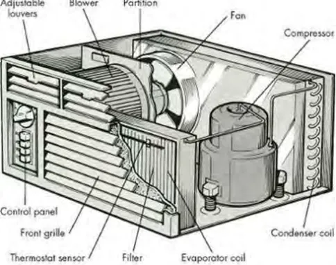
[image:17.612.207.449.480.671.2]Window air-conditioner usually been used for a small space area. In this air-conditioner all components, namely the evaporator, compressor, condenser and thermal expansion valve been installed in a single box house. All the components are assembled inside the casing and been install on the wall which casing of the conditioner is been fitted into the wall or window of the room. Window air-conditioner can be divided into two compartments which are the room side and the outdoor side. On the room side, the casing is decorated beautifully and consists of supply and return air grills and commonly called as front grill. Outdoor side consists of condenser system in which heat is removed to the atmosphere. Figure 2.2 show type of window air-conditioner.
6 b) Package terminal air-conditioner
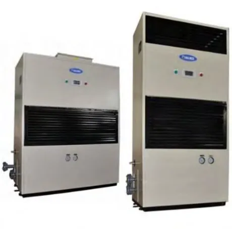
[image:18.612.211.441.411.638.2]Window air-conditioner and split unit-air conditioner normally use for residential or small air-conditioner capacities. Using the same concept as split unit and window unit air-conditioner, packaged terminal unit air-conditioner is used for largest cooling load capacity extend beyond 20 tons and often found in hotels or offices. All the component consists of compressor, condenser, expansion valve and cooling coil installed together in cabinet casing with an addition of its own air handler unit and filter. Normally packaged terminal air-conditioner placed on the roof or a concrete slab near the foundation. Packaged terminal air-conditioner supply the air to the rooms using ducting system. Packaged terminal air-conditioner condenser can be cool either using water or air. Generally, water is chosen to cool the condenser using cooling tower because the usage of water is more efficient compared to air-cooled condenser. Figure 2.3 show terminal package air-conditioner.
7 c) Split unit air-conditioner
[image:19.612.249.440.432.677.2]This type of air-conditioner been used in this project. Usage of split-type air-conditioner in office buildings and residential been famous due to the simplicity and flexibility (Avara & Daneshgar, 2008). Normally, small and medium residential building used split unit air-conditioner (Elsayed & Hariri, 2011). Split type air-conditioner comprises of two parts which is indoor unit and outdoor unit. Indoor unit been installed on the wall inside the room and consists of evaporator or cooling coil and cooling fan. The most common type of the indoor unit is the wall mounted type. However, other types such as ceiling mounted and floor mounted are also used. Outdoor unit are normally installed on the outside of the rooms and contain condenser, compressor and thermal expansion valve. Indoor and outdoor unit are connected together using copper pipes. Split unit air-conditioner can be used to cool down more than one room. Variable indoor unit with single outdoor unit can be used on multiple rooms and been call multi-split unit conditioner. Figure 2.4 show split unit type air-conditioner
8
2.1.1 Types of Split Unit Air Conditioner
i. Multi split unit air-conditioner
Multi-split unit air-conditioner consists of one indoor unit with multiple outdoor units. The purpose of multi-split unit air-conditioner is to cool multiple zone interior space. All the indoor units are connected to the outdoor unit using different piping lines. Total of piping lines depends on the number of indoor units that are used in the building. The usage of multi-split unit air-conditioner solves the outdoor unit arrangement problem because it only used single outdoor unit. Total cooling load of indoor units and outdoor unit need to be balance in order to produce high performance result. Furthermore, this type of air-conditioner can be used to cool certain rooms at certain times which means not all the indoor unit need to be switch on to make the system run.
ii. Single split unit air-conditioner
9
2.2 Model of split unit air-conditioner
Split unit air-conditioner have improved rapidly to increase the efficiency of the system. A lot of improvement had been done to create system that is more efficient compared to the previous system. The improvement of split unit air-conditioner has produced two models that is constant speed and inverter.
2.2.1 Inverter
Inverter air-conditioner is the latest evolution of technology consist of electro motor of the compressor. Improvements and reduction in the energy consumption of refrigerator compressors is crucial for the refrigeration industry (Ekren, Celik, Noble, & Krauss, 2013). The function of inverter is to control the speed of the compressor. Inverter compressor run at variable speed, at a low speed when the room in the right temperature and speeds up when the temperature increased. Compared to the constant speed air-conditioner, inverter compressor produced silent sound when in use because the compressor speed is controlled according to the room temperature which minimize the vibration on the compressor. Inverter air-conditioner also cool the room at a constant temperature that lead to the comfortable rooms. In term of power consumption, inverter saved more energy compared to the constant speed because of the control over compressor speed reduced the usage of electrical power. The refrigerant used in inverter is R-410a.
2.2.2 Constant speed
10 turn on after the temperature in the room increased. Furthermore, the usage of constant speed air-conditioner produce unpleasant sound that is caused by vibration. When the temperature start going up, the compressor will start to run at maximum capacity hence the unpleasant sound produced. Constant speed compressor is less efficient in term of power consumption because the compressor will always run at maximum capacity when it is started which will result in the large usage of electrical power. Normally, the refrigerant that is used in constant speed is R-22. This model is used in this project.
2.2.3 Refrigerant used
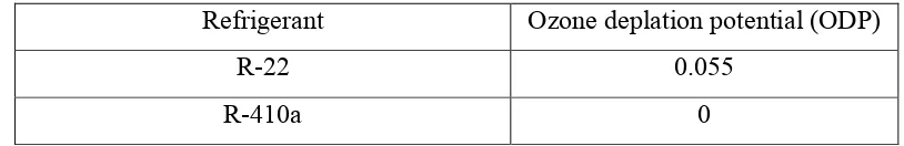
11 Table 2. 1: Ozone depletion potential
Refrigerant Ozone deplation potential (ODP)
R-22 0.055
R-410a 0
12
2.3 Component arrangement
There are four basic components required to complete the refrigerant basic cycle. All the refrigerants use this system in a closed circuit. The same refrigerant is used in this cycle to cool the space area and to remove the heat to atmosphere. The four main components are evaporator, compressor, expansion valve and condenser.
2.3.1 Evaporator
Evaporator is a device that assembled in the indoor unit air-conditioners used to absorb heat and cool the space area. Refrigerant flow into the evaporator in low pressure liquid and flow out into discharge line in low pressure vapor after absorbed the heat from the space that is being cooled. Air from surrounding has been forced to the evaporator coil and fin using blower. The cooling process begin when the air flow passed through the evaporator coil for heat exchanger. The air produced at the evaporator flow to the space are cooled air.
2.3.1.1 Types of evaporator
There are several types of evaporators been used in air-conditioning system and been selected using their specific application and design. Normally evaporator selected depending on the construction of the evaporator. These are types of evaporator that commonly used in air-conditioning system:
a. Bare tube evaporator b. Finned type evaporator c. Plate type