MICROWAVE FILTER - STEPPED IMPEDANCE LOWPASS FILTER AT 2.4GHz
AHMAD RIDZUAN BIN AB. WAHAB
This report is submitted in partial fulfillment of the requirement for the award of Bachelor of Electronic Engineering (Telecommunication Electronics) With Honours
Faculty of Electronic and Computer Engineering Universiti Teknikal Malaysia Melaka
UNIVERSITI TEKNIKAL MALAYSIA MELAKA
FAKULTI KEJURUTERAAN ELEKTRONIK DAN KEJURUTERAAN KOMPUTER
w
I-
BORANG PENGESAHAN STATUS LAPORAN PROJEK SARJANA MUDA I1
Tajuk Projek Microwave Filter - Stepped Impedance Lowpass Filter At
2.4GHz
Sesi
:
...
.2007/2008....
Pengajian
Saya AHMAD RIDZUAN BIN AB WAHAB
(HURUF BESAR)
mengaku membenarkan Laporan Projek Sarjana Muda ini disimpan di Perpustakaan dengan syarat- syarat kegunaan seperti berikut:
1. Laporan adalah hakmilik Universiti Teknikal Malaysia Melaka.
2. Perpustakaan dibenarkan membuat salinan untuk tujuan pengajian sahaja.
3. Perpustakaan dibenarkan membuat salinan laporan ini sebagai bahan pertukaran antara institusi pengajian tinggi.
4. Sila tandakan ( .\I ) :
(Mengandungi maklumat yang berdarjah keselamatan atau
kepentingan Malaysia seperti yang termaktub di dalam AKTA
RAHSIA RASMI 1972)
(Mengandungi maklumat terhad yang telah ditentukan oleh organisasihadan di mana penyelidikan dijalankan)
Ahmat Tetap: 1019 Lorong 4, Kg Merbau Sempak
DYA ABDUL RANI BIN OTHMAN
Profesor Madya
47000 Sg. Buloh, Selangor ~ a r u ~ Ehsan dan Kej Komputer (FKEKK), Universiti Teknikal Malaysia Melaka (UTeM),
Karung Berkunci 1200,
DECLARATION
"I hereby declare that this report is the result of my own work except for the quite as
cited in the reference."
Signature :
.
..
.
.
Author
@g$i$$-.:
.... . . ..
: Ahmad Ridzuan Bin AB. Wahab
"I hereby declare that I have read this report and in my opinion this report is
sufficient in terms of the scope and quality for the purpose of award of the Degree in
Bachelor of Electronic Engineering (Telecommunication Electronic)%ith Honour"
n
Signature
To my belovedparents:
ACKNOWLEDGEMENT
First and foremost, I would like to give Thanks to ALLAH SWT, for helping me
through all the obstacles that I encountered during the work of this project.
I would like to express my heartily gratitude to my supervisors, Mrs.
Maisarah Binti Abu and Abdul Rani Bin Othrnan for the guidance and enthusiasm
given throughout the progress of this project.
My appreciation also goes to my family who has been so tolerant and
supports me all these years. Thanks for their encouragement, love and emotional
supports that they had given to me.
Nevertheless, my great appreciation dedicated to all my best friends, BENT
member's batch 2004 to 2008 and those whom involve directly or indirectly with this
ABSTRACT
This project presents the design of microwave lowpass filter for wireless local
area network application operating at 2.4GHz frequency. The designed filter is
Chebyshev response type two stepped impedance structure with pass bandwidth of
0.0835GHz. It has been observed that the minimum attenuation is less than -23dB at
3GHz frequency, insertion loss of 6.042dB, passband ripple of 4.326dB and stopband
ripple is 15dB. Simulation and optimisation uses Microwave Office software and the
ABSTRAK
Projek ini menerangkan tentang reka bentuk penapis gelombang mikro
untuk kegunaan jaringan tempatan tanpa wayar yang beroperasi pada lingkaran
2.4GHz. Jenis penapis yang telah direka adalah penapis galangan-tangga Chebyshev
jenis dua yang mempunyai lebar-jalur 0.0835GHz. Pemerhatian yang dilakukan
mendapati susutan minimum adalah lebih rendah dari -23dB pada 3GHz frekuensi,
kehilangan sisipan pada 6.042dB, riak gelombang pada lulus-jalur adalah 4.326dB
dan riak gelombang pada henti-jalur adalah 15dB. Simulasi dan pengoptimum telah
dilakukan menggunakan perisian Microwave Office dan perlaksanaan fabrikasi
...
VlllTABLE OF CONTENTS
CHAPTER ITEM
TITLE DECLARATION APPROVEMENT DEDICATION ACKNOWLEDGEMENT ABSTRACT ABSTRAK
TABLE OF CONTENT
LIST OF TABLES
LIST OF FIGURES
LIST OF APPENDICES
ABBREVIATIONS
INTRODUCTION
1.1 Introduction
1.2 Objective
1.3 Literature Review
1.4 Scope of Project
1.5 Project's Methodology
1.6 Expected Result
I1 LITERITURE REVIEW
2.1 Lowpass filter in WLAN application.
2.2 Microstrip Technology
2.2.1 Overview of Microstrip
2.2.2 Effect of Dielectric Constant
2.2.3 Effect of Strip Thickness
2.2.4 Effect of Enclosure
2.3 Substrate Material
I11 LOWPASS FILTER THEORY
3.1 Introduction to Lowpass filter
3.2 Scattering Parameters
3.3 Losses in Transmission Line
3.3.1 Insertion Loss
3.3.2 Return Loss
3.3.3 Transmission Line or Attenuation
3.4 Synthesis Technique
3.4.1 Insertion Loss Method
3.5 Filter Response
3.5.1 Chebyshev Response
IV METHODOLOGY
4.1 Introduction
4.2 Designing a Low Pass Prototype (LPP) Filter
4.2.1 Step 1 - Find nth element of LPP
4.2.2 Step 2
-
Perform Impedance andFrequency Scaling
4.2.3 Step 3 - Designing Using Microstrip 4.3 Simulation Using Microwave Office Software
4.3.1 Simulation Procedure
4.4 Fabrication
RESULT, ANALYSIS AND DISCUSSION
5.1 Simulation Result
5.2 Filter Optimisations
5.3 The Result Afler Optimisations Process
5.4 Experimental Result
VI CONCLUSION, RECOMMENDATIONS AND
FUTURE WORKS
6.1 Conclusion
6.2 Recommendations
6.3 Future Works
REFERENCES
LIST OF TABLES
NO.
1.1
TITLE
Expected result of the filter
FR-4 specification
Ripple factor 2010glo E = 0.5dB
Component's Value of Lumped Element Network
Transmission line properties
Characteristic of filter element
Dimension of the filter
Simulation Result after optimisation process
Comparison between WLAN requirement,
simulation and experimental result
LIST OF FIGURES
NO.
TITLEFlow chart of Methodology.
General block diagram of WLAN transmitter Microstrip dielectric layers
A lowpass filter frequency response
Amplitude response of Butterworth, Chebyshev
and Bessel filter using (3.9)
Lumped element lowpass filter
Equivalent T-network for transmission line with
length I
The top view of microstrip stepped impedance
lowpass filter
Determine transmission line of microstrip filter
using Microwave Office software
Circuit by section lowpass filter
Layout of microstrip stepped impedance filter
Measurement process
Lumped element simulation result
Simulation result for circuit by section of
lowpass filter
EM structure simulation result
Layout of microstrip filter after optimisation
process
Simulation result for circuit by sections of filter
Simulation Result for EM Stucture
5.7 Microstrip Stepped Impedance Lowpass Filter
on FR-4 Substrate
xiv
LIST OF APPENDICES
NO. DESCRIPTION
A Attenuation versus normalized
frequency for equal-ripple filter
prototypes; 0.5 dB ripple level.
B Calculation for Chebyshev ripple
factor 2010gloE = 0.5dB
ABBREVIATIONS EBG IEEE FR-4 ISM LTCC LPF LPP MLIN MSTEP MSUB PCB PDA SMA TEM TLM
uv
VSWR WLANElectromagnetic Band Gap
Institute of Electrical and Electronics Engineers
ElectroMagnetic
Flame Retardant 4
Industrial, Scientific and Medical
Low Temperature Co-fired Ceramics
Low Pass Filter
Low Pass Prototype
Microstrip Line (Closed Form)
Microstrip Step in Width (Closed Form)
Microstrip Substrate Definition
Printed Board Circuit
Personal Digital Asassistant
Sub-Miniature version A
Transverse ElectroMagnetic
Transmission Line Method
Ultra-Violet
Voltage Standing Wave Ratio
Wireless Local Area Network
Modulated Frequency
Relative Dielectric Constant
Effective Permeability
Substrate Height
Substrate Thickness
Length
CHAPTER I
INTRODUCTION
1.1 Introduction
Microwave filter are two-port network, reciprocal, passive, linear device
which attenuate heavily the unwanted signal frequencies while permitting
transmission of wanted frequencies [I]. The type of construction of this filter is a
reflective filter which is consists of capacitive and inductive elements producing
ideally zero reflection loss in the pass band region and very high attenuation in the
stop band region. The practical filters have small non-zero attenuation in the pass
band a small signal output in the attenuation or stop band due to the presence of
resistive losses in reactive elements of propagating medium [I]. The proposed
Microstrip Stepped-Impedance lowpass filter is designed for 2.4 GHz operating
frequency which is suitable for ISM band (Industry, Scientific and Medical) with
attenuation at 3GHz stop bandwidth [2].
The stepped impedance distribution element filter is one of the most popular
microstrip filter configurations used in the lower microwave frequencies. It is easy to
manufacture because it has open-circuited ends and it is easy to design. Microstrip
filters play an important role in many RF applications. As technologies advances,
more stringent requirements for filters are required. One of the requirements is
1.2 Objective
The objective of this project is to design a micostrip lowpass filter (LPF)
using microstrip technology. This filter designed for wireless local area network
(WLAN) application.
1.3 Literature Review
In modem wireless telecommunication system, compact size and high
performance filter are commonly required to reduce the cost and enhance system
performance. The use of microwave filters can be found in many applications in
microwave circuits and telecommunication systems, implemented in a number of
topologies. One of the conventional filters is the stepped impedance filter mainly due
to the ease of implementation in either microstrip or coplanar technology [8], [12],
[131.
Earlier filter designs have mostly been focused on using a modified silicon
substrate where the variation in substrate height and effective permittivity is
accomplished by etching [14]. Different concepts and materials have been suggested
for achieving a high dielectric constant and also the advantage of being tunable by
varying the composition. Several ideas of how to perform this with different
technologies have been presented [19]. Also commercially available low temperature
co-fired ceramics (LTCC) tapes exist with dielectric values of about 4 to 10. These
tapes, together with high dielectric constant ceramics (bi-pyrochlore), could also be
combined and used for achieving a variation in dielectric constant [19].
The stepped impedance filter is normally design by alternating low and high
impedance regions where the change in impedance is controlled by the line width of
the strip. For achieving a high degree of attenuation in the stop band, it is necessary
to obtain a 'high to low impedance ratio' (ZH=ZL) or increase the order of the filter.
If a dielectric homogeneous substrate is used the limitations are directly related to the
achievable line widths. In addition, to arrive at narrow line widths could also be
difficult due to process limitations (minimum possible feature size). By using a non-
introduced, it would be possible to create a stepped impedance filter with a
continuous microstrip width.
Other designs have also utilised the method of etching the ground plane to
producing a variation in the effective permittivity [15], [16], [17]. However, using
etching ground plane will locally change the effective permittivity. The technology
of etching the ground plane will also introduce unwanted radiation in microwave
applications and therefore require necessary shielding. Therefore other designs
utilising materials with different dielectric constants could offer a new possibility to
produce filters and other devices [18].
Recently, the new stepped impedance geometry with different working
principle, design procedure, performance, and physical size, mediate, and high
working frequency have been introduced. It is called electromagnetic bandgap
structure (EBG structure) [17], [20], [21]. The comparison between these two
techniques and analysis is explained on [22]. This EBG structure has the advantage
working in higher frequency and high attenuated in the stopband. Less size that
conventional stepped impedance geometry. However, the ripples level of in the
passband of this EBG structure higher that conventional stepped impedance
technique.
In combination with progress in finding new high dielectric constant
materials this could be an interesting technology for improving some of the filter
performances. The size reduction of the filter could also become an important factor
where large line widths could be replaced by smaller line widths by introducing a
higher dielectric constant.
For the conclusion, I choose to design a conventional geometry of microstrip
lowpass filter using high and low impedance technique. Various numerical method
have been developed by a number of researchers to ease simulation effort when
designing microstrip lowpass filters [2], [12], [13] which includes transmission line
method (TLM). TLM is a technique for solving Maxwell's equation in the presence
and design. TLM has been popular in the construction of an equivalent circuit model
due to its accuracy and numerical efficiency.
1.4 Scope of Project.
Several important parameters generally considered are pass bandwidth,
stopband attenuation and frequencies, insertion loss and return loss. This filter
operates in the ISM frequency band covering 2.4 GHz to 2.4835 GHz. The filters
discussed in this project are design to have pass bandwidth of 0.0835GHz with
minimum stop band attenuation of -23dB at 3GHz and insertion loss below 1 OdB and
also designed to operate between terminated impedance 50ohrn which is typical used
for WLAN system. The filters are designed using Microwave Office design software
and implemented on flame redundant (FR-4) substrate with dielectric constant of 4.7,
loss tangent of 0.019 and substrate height of 1.6mm.
Several scopes of work have been determined are:-
1 Doing literature review by referring to related books and IEEE journal.
2 To calculate the stepped impedance lowpass filter, design and simulate the
filter using Microwave Office to met WLAN specification.
3 To obtain the physically dimension filter values, dielectric material
characteristic and obtain frequency response of the filter.
4 To fabricate filter on the microstrip board
5 Analysis will be carried out to compare the simulation and the measurement
result.
1.5 Project's Methodology
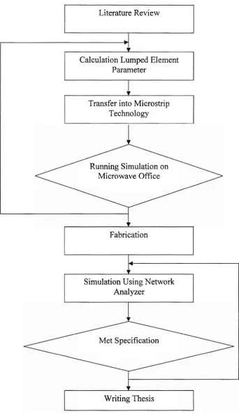
Figure 1.1 shows the flow chart of this project. It used as general plan to get this
project done. This project involves 4 major phases:
1 st phase: Literature Review
o Doing research to know the detail about designing dual-plane microstip low pass filter.
o Study of the software implementation (Microwave Office)
o Have meeting with supervisor and lecturers.
2nd phase: Calculation and analysis
o Analyzed and calculated all the parameters that related to design the Step
impedance filter and.
o Using Matlab software to calculate physical dimension and all parameters
needed.
3rd phase: Software Implementation development
o Used software (Microwave Office) to design and measurement of filter. o To obtain the precise value using this software.
4th phase: Hardware Development
o Then proceed to design microstrip filter using etching technique and do the
measurement using spectrum analyzer. Finally, comparison between
Literature Review
Calculation Lumped Element Parameter
Transfer into Microstrip Technology
Running Simulation on Microwave Office
Fabrication
Simulation Using Network Analyzer
Met Specification
[image:22.540.143.486.49.646.2]Writing Thesis
1.6 Expected Result
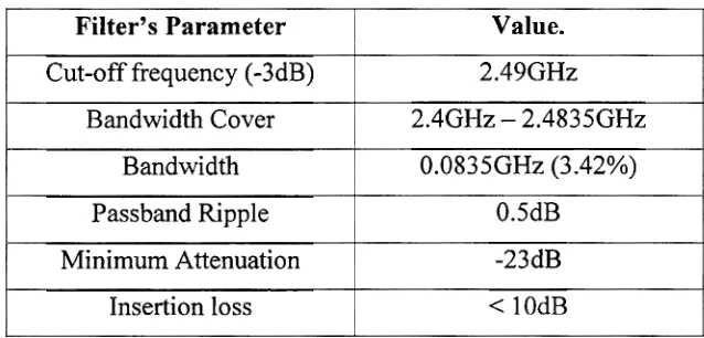
From [27], [28], we identified the filter specifications that have specific
value in order to meet the WLAN filter specifications requirement. The filter will be
developed using FR-4 substrate with the following specifications. Table 1.1 shows
[image:23.540.115.434.239.392.2]the expected result of the WLAN filter.
Table 1.1 : Expected result of the filter.
Filter's Parameter Cut-off frequency (-3dB)
Bandwidth Cover
Bandwidth
Passband Ripple
Minimum Attenuation
Insertion loss
Value. 2.49GHz
2.4GHz - 2.4835GHz 0.0835GHz (3.42%)
0.5dB
-23dB
CHAPTER I1
LITERITURE REVIEW
2.1 Lowpass Filter in WLAN application.
Microstrip filters play various roles in wireless or mobile communication
systems. Microwave and RF filters are widely used in this system in order to
discriminate between wanted and unwanted signal frequencies [3]. The concept of a low-pass filter exists in many different forms, including electronic circuits (like a
hiss j l t e r used in audio), digital algorithms for smoothing sets of data, acoustic
barriers, blurring of images, and so on. Implementations of lowpass filter in WLAN
application shown in Figure 2.1. The input baseband signal which is included voice,
data, and video is assumed to be at a frequency
f,.
A lowpass filter serves to removefrequency beyond the passband of the channel [2]. Lowpass filter is designed for use
in harmonic rejection applications for cellular handsets, wireless PDA's, and IEEE
802.1 1 b WLAN which might cause interference with other communications [30]. It's
provided high harmonic attenuation respectively at a maximum insertion loss of
0.5dB. Lowpass filter also determine the voice performance in the data signal.
Basically, communication is the process of transmission information from
transmitter to receiver. The microstrip filter is either of suitable component that are