Routing events using the Grid Event Service
Shrideep Pallickara
∗Geoffrey C. Fox
†Contents
1 Introduction 3
2 The distributed model for the servers 6
2.1 The Server Node Topology . . . 6
2.1.1 GES Contexts . . . 8
2.1.2 Gatekeepers . . . 8
2.1.3 The addressing scheme . . . 9
3 The problem of event delivery 10 3.1 The node organization protocol . . . 11
3.1.1 Adding a new node to the system . . . 11
3.1.2 Adding a new unit to the system . . . 13
3.2 The gateway propagation protocol - GPP . . . 13
3.2.1 Organization of gateways . . . 13
3.2.2 Constructing the connectivity graph . . . 14
3.2.3 The connection . . . 15
3.2.4 Link count . . . 15
3.2.5 The link cost matrix . . . 16
3.2.6 Organizing the nodes . . . 16
3.2.7 Computing the shortest path . . . 17
3.2.8 Building and updating the routing cache . . . 17
3.2.9 Exchanging information between super-units . . . 18
3.3 Organization of Profiles and the calculation of destinations . . . 19
3.3.1 The problem of computing destinations . . . 19
3.3.2 Constructing a profile graph . . . 19
3.3.3 Information along the edges . . . 21
3.3.4 Computing destinations from the profile graph . . . 21
3.3.5 The profile propagation protocol - Propagation of±δω changes . . . 22
3.3.6 Unit additions and the propagation of profiles . . . 23
3.3.7 Active profiles . . . 23
3.4 The event routing protocol - ERP . . . 24
3.5 Routing real-time events . . . 26
3.5.1 Events with External Destination lists . . . 26
3.5.2 Events with Internal Destination lists . . . 27
3.6 Unique Events - Generation of unique identifiers . . . 27
3.7 Duplicate detection of events . . . 28
3.8 Interaction between the protocols and performance gains . . . 29
LIST OF FIGURES 2
4 Results 31
4.1 Experimental Setup . . . 31
4.2 Factors to be measured . . . 31
4.2.1 Measuring the factors . . . 31
4.3 Discussion of Results . . . 33
4.3.1 Latencies for the routing of events to clients . . . 33
4.3.2 System Throughput . . . 35
4.3.3 Variance . . . 35
4.3.4 Pathlengths and Latencies . . . 37
4.4 Summary of results . . . 41
5 Future Directions: The need for dynamic topologies 42 6 Conclusion 43
List of Figures
1 A Super Cluster - Cluster Connections . . . 62 A Super-Super-Cluster - Super Cluster Connections . . . 7
3 Gatekeepers and the organization of the system . . . 9
4 Adding nodes and units to an existing system . . . 12
5 Connectivities between units . . . 14
6 The connectivity graph at node 6. . . 17
7 Connectivity graphs after the addition of a new super cluster SC-4. . . 18
8 The profile graph - An example. . . 20
9 The complete profile graph with information along edges. . . 21
10 The connectivity graph at node 6. . . 23
11 Routing events . . . 25
12 Duplicate detection of events . . . 28
13 Duplicate detection of events during a client roam . . . 29
14 Testing Topology - (I) . . . 32
15 Match Rates of 100 . . . 34
16 Match Rates of 50 . . . 34
17 Match Rates of 25 . . . 35
18 Match Rates of 10 . . . 36
19 System Throughput . . . 36
20 Testing Topology - Latencies versus server hops . . . 37
21 Match Rates of 50% - Server Hop of 4 . . . 38
22 Match Rates of 50% - Server Hop of 2 . . . 39
23 Match Rates of 50% - Server Hop of 1 . . . 39
24 Match Rates of 10% - Server Hop of 4 . . . 40
25 Match Rates of 10% - Server Hop of 2 . . . 40
26 Match Rates of 10% - Server Hop of 1 . . . 41
List of Tables
1 The Link Cost Matrix . . . 162 Reception of events at C . . . 28
3
1
Introduction
Developments in the pervasive computing area, have led to an explosion in the number of devices that users employ to communicate with each other and also to access services that they are interested in. These devices have different computing and content handling capabilities. Further, these users do not maintain an online presence at all times and access services after prolonged disconnects. The channel employed to access services may have different bandwidth constraints depending on the channel type and also on the service being accessed. The system we are considering needs to support communications for 109 devices. The users using these devices would be interested
in peer-to-peer (P2P) style of communication, business-to-business (B2B) interaction or a system comprising of agents where discoveries are initiated for services from any of these devices. Finally, some of these devices could also be used as part of a computation. The devices are thus part of a complex distributed system. In our model we have the notion of logical clients. These logical clients exist since there could be one or more devices that belong to a single physical user. We make no assumptions regarding a client’s computing power or the reliability of the transport layer over which it communicates. Clients have profiles, which indicate the type of events and servicing that they are interested in.
To support the large number of clients that exist within the system we have a distributed network of servers. These servers are responsible for intelligently routing events within the system. This routing should be such that an event is routed to a server only if it is en route to a valid destination for the event. Distributed messaging systems broadly fall into three different categories. Namely queuing systems, remote procedure call based systems and publish subscribe systems. Message queuing systems with their store-and-forward mechanisms come into play where the sender of the message expects someone to handle the message while imposing asynchronous communication and guaranteed delivery constraints. The two popular products in this area include IBM’s MQSeries [23] and Microsoft’s MSMQ [22]. MQSeries operates over a host of platforms and covers a much wider gamut of transport protocols (TCP, NETBIOS, SNA among others) while MSMQ is optimized for the Windows platform and operates over TCP and IPX. A widely used standard in messaging is the Message Passing Interface Standard (MPI) [16]. MPI is designed for high performance on both massively parallel machines and workstation clusters. Messaging systems based on the classical remote procedure calls include CORBA [30], Java RMI [26] and DCOM [15]. Publish subscribe systems form the third axis of messaging systems and allow for decoupled communication between clients issuing notifications and clients interested in these notifications.
The decoupling relaxes the constraint that publishers and subscribers be present at the same time, and also the constraint that they be aware of each other. The publisher is also unaware of the number of subscribers that are interested in receiving a message. The publish subscribe model does not require synchronization between publishers and subscribers. By decoupling this relationship between publishers and consumers, security is enhanced considerably. The routing of messages from the publisher to the subscriber is within the purview of the message oriented middleware (MOM) which is responsible for routing the right content to the right consumers. The publish subscribe paradigm can support both pull and push paradigms. In the case of pull, the subscribers retrieve messages from the MOM by periodic polling. The push model allows for asynchronous operations where there are no periodic pollings. Industrial strength products in the publish subscribe domain include solutions likeTIB/Rendezvous [14] from TIBCO and SmartSockets [13] from Talarian. Variants of publish subscribe include systems based on content based publish subscribe. Content based systems allow subscribers to specify the kind of content that they are interested in. These content based publish subscribe systems include Gryphon [5, 2], Elvin [33] and Sienna [8]. The system we are looking at, the grid event service (GES), is also in the realm of content based publish/subscribe systems with the additional feature of location transparency for clients.
4
to include publish subscribe features into its messaging middleware include efforts like JMS [20] and JINI [3]. One of the goals of JMS is to offer a unified API across publish subscribe implementations. Various JMS implementations include solutions like SonicMQ [12] from Progress, JMQ [25] from iPlanet,iBus [24] from Softwired andFioranoMQ [11] from Fiorano.
In the systems we are studying, unlike traditional group multicast systems, groups cannot be pre-allocated. Each message is sent to the system as a whole and then delivered to a subset of recipients. The problem of reliable delivery and ordering1 in traditional group based systems with
process crashes has been extensively studied [19, 7, 6]. These approaches normally have employed the
primary partition model [32], which allows the system to partition under the assumption that there would be a unique partition which could make decisions on behalf of the system as a whole, without risk of contradictions arising in the other partitions and also during partition mergers. However the delivery requirements are met only within the primary partition [18]. Recipients that are slow or temporarily disconnected may be treated as if they had left the group. This model works well for problems such as propagating updates to replicated sites. This approach doesn’t work well in situations where the client connectivity is intermittent, and where the clients can roam around the network. The main differences between the systems being discussed here and traditional group-based systems are:
1. We envision relatively large, widely distributed systems. A typical system would comprise of hundreds of thousands of broker nodes, with tens of millions of clients.
2. Events are routed to clients based on their profiles, employing the group approach to routing the interesting events to the appropriate clients would entail an enormous number of groups -potentially 2ngroups fornclients. This number would be larger since a client profile comprises of interests in varying event footprints.
The approach adopted by the OMG [29, 28] is one of establishing channels and registering suppliers and consumers to those event channels. The event service [29] approach has a drawback in that it entails a large number of event channels which clients (consumers) need to be aware of. Also since all events sent to a specific event channel need to be routed to all consumers, a single client could register interest with multiple event channels. The aforementioned feature also forces a supplier to supply events to multiple event channels based on the routing needs of a certain event. On the fault tolerance aspect, there is a lack of transparency since channels could fail and issuing clients would receive exceptions. The most serious drawback in the event service is the lack of filtering mechanisms. These are sought to be addressed in the Notification Service [28] design. However the Notification service attempts to preserve all the semantics specified in the OMG event service, allowing for interoperability between Event service clients and Notification service clients. Thus even in this case the client needs to subscribe to more than one event channel.
In this paper we propose the Grid Event Service (GES) where we have taken a system model that encompasses Internet/Grid messages. GES is designed to include JMS as a special case. However, GES provides a far richer set of interactions and selectivity between clients than the JMS model. GES is not restricted to Java of course, this is our initial implementation. We envision a system with thousands of broker nodes providing a distributed event service in a federated fashion. In GES a subscribing client can attach itself to any of the broker nodes comprising the system. This client specifies the type of events it is interested in through its profile. We have employed a distributed network of broker nodes primarily for reasons of scaling and resiliency. A large number of broker nodes can support a large number of clients while at the same time eliminating the single point of failure in single broker systems. These broker nodes are organized as a set of strongly connected broker nodes comprising a cluster; clusters in turn are connected to other such clusters by long links. This scheme provides for small world networks, which in the spectrum of strongly connected graphs falls in between regular graphs and random graphs. The advantage of suchsmall world networks[35] is that the averagepathlengthof any broker node to any other broker node increases logarithmically with the geometric increases in the size of the network.
5
6
2
The distributed model for the servers
One of the reasons why one would use a distributed model is high availability. Having a centralized model would imply a single server hosting multiple clients. While, this is a simple model, the inherent simplicity is more than offset by the fact that it constitutes a single point of failure. Thus all the clients present in the system would be unable to use any of the services provided by the system till a recovery mechanism kicks in.
A highly available distributed solution would have data replication at various server nodes in the network. Solving issues of consistency while executing operations, in the presence of replication, leads to a model where other server nodes can service a client despite certain server node failures. The underlying network that we consider for our problem is one made up of the nodes that are hooked onto the Internet or Intranets. We assume that the nodes which participate in the event delivery can crash or be slow. Similarly the links connecting these node may fail or get overloaded. These assumptions are drawn based on real life experiences. One of the immediate implications of our delivery guarantees and the system behavior is that profiles are what become persistent, not the client connection or its active presence in the digital world at all times.
2.1
The Server Node Topology
The smallest unit of the system is a server node and constitutes a unit at level-0 of the system. Server nodes grouped together form a cluster, the level-1 unit of the system. Clusters could be clusters in the traditional sense, groups of server nodes connected together by high speed links. A single server node could also decide to be part of such traditional clusters, or along with other such server nodes form a cluster connected together by geographical proximity but not necessarily high speed links.
Cluster-A
Cluster-D Cluster-C
Cluster-B
d c
a b
l k
i j
p o
m n
h g
[image:6.612.192.456.381.583.2]e f
Figure 1: A Super Cluster - Cluster Connections
2.1 The Server Node Topology 7
SuperCluster-I
SuperCluster-II
SuperCluster-III
[image:7.612.169.487.79.301.2]SuperCluster-IV SuperCluster-V
Figure 2: A Super-Super-Cluster - Super Cluster Connections
This topology could be extended in a similar fashion to constitute asuper-super-cluster (level-3 unit) as shown in figure 2,super-super-super-clusters(level-4 units) and so on. A client thus connects to a server node, which is part of a cluster, which in turn is part of a super-cluster and so on and so forth. We limit the number of super-clusters within a super-super-cluster, the number of clusters within a super cluster and the number of nodes within a cluster viz. theblock-limit to 64. In an N-level system this scheme allows for 26
N×26N−1× · · ·260 i.e 26∗(N+1)server nodes to be present in
the system.
What we essentially have here is a set of strongly connected server nodes comprising a cluster and a set of links connecting a cluster to other clusters. We are interested in the delays that would be involved in connecting from one node in the network to another node in the network. This is proportional to the server node hops that need to be taken en route to the final destination.
We now delve into the small world graphs introduced in [35] and employed for the analysis of real world peer-to-peer systems in [31, pages 207 – 241]. In a graph comprising several nodes,
pathlengthsignifies the average number of hops that need to be taken to reach from one node to the other. Clustering coefficient is the ratio of the number of connections that exist between neighbors of node and the number of connections that are actually possible between these nodes. For a regular graph consisting ofnnodes, each of which is connected to its nearestkneighbors – for cases where n≫k≫1, the pathlength is approximatelyn/2k. As the number of vertices increases to a large value the clustering coefficient in this case approaches a constant value of 0.75.
2.1 The Server Node Topology 8
2.1.1 GES Contexts
Every unit within the system, has a unique Grid Event Service (GES) context associated with it. In anN-level system, a server exists within the GES contextC1
i of a cluster, which in turn exists within the GES context C2
j of a super-cluster and so on. In general a GES contextCiℓ at level ℓ exists within the GES contextCjℓ+1of a level (ℓ+ 1). In anN-level system the following hold —
C0
i = (Cj1, i) (1)
Cj1 = (Ck2, j) (2)
.. . CN−2
p = (CN−1, p) (3)
CN−1
q = q (4)
In anN-level system, a unit at levelℓcan be uniquely identified by (N−ℓ) GES context identifiers of each of the higher levels. Of course, the units at any level ℓwithin a GES context Ciℓ+1 should be able to reach any other unit within that same level. If this condition is not satisfied we have a
network partition.
2.1.2 Gatekeepers
Within the GES context C2
i of a super-cluster, clusters have server nodes at least one of which is connected to at least one of the nodes existing within some other cluster. In some cases there would be multiple links from a cluster to some other cluster within the same super-clusterC2
i. This architecture provides a greater degree of fault tolerance by providing multiple routes to reach the same cluster. Some of the nodes in the cluster thus maintain connections to the nodes in other clusters. Similarly, some nodes in a cluster could be connected to nodes in some other super-cluster. We refer to such nodes as gatekeepers. Nodes, which maintain connections to other nodes in the system, have different GES contexts. Depending on the highest level at which there is a difference in the GES contexts of these node, the nodes that maintain this active connection are referred to as the gatekeeper at that level. Nodes, which are part of a given cluster, have GES contexts that differ at level-0. Every node in a cluster is connected to at least one other node within that cluster. Thus, every node in a cluster is a gatekeeper at level-0.
Let us consider a connection, which exists between nodes in a different cluster, but within the same super-cluster. In this case the nodes that maintain this connection have different GES cluster contexts i.e. their contexts at level-1 are different. These nodes are thus referred to as gatekeepers at level-1. Similarly, we would have connections existing between different super-clusters within a super-super-cluster GES context C3
i. In anN-level system gatekeepers would exist at every level within a higher GES context. The link connecting two gatekeepers is referred to as the gateway, which the gatekeepers provide, to the unit that the other gatekeeper is a part of. A gatekeeper at levelℓwithin a higher GES contextCjℓ+1, denotedgℓi(Cjℓ+1), comprises of –
• The higher level GES ContextCjℓ+1 • The gatekeeper identifieri
• The list of gatekeepers at level ℓthat it is connected to, within the GES contextCjℓ+1. It should be noted that a gatekeeper at levelℓcan be a gatekeeper at any other level. In fact, every node within the system is a gatekeeper at level-0. Figure 3 shows a system comprising of 78 nodes organized into a system of 4 super-super-clusters, 11 super-clusters and 26 clusters. When a node establishes a link to another node in some other cluster, it provides a gateway for the dissemination of events. If the node it connects to is in a different cluster within the same super-cluster GES contextC2
2.1 The Server Node Topology 9
SSC-A SC-1
SC-2
SC-3
e
g c
b
f d
a
SSC-B SC-4
SC-5
SC-6 l
n i
j
m
k
h
SSC-C SC-7
SC-8
SC-9 s
u o
q
t r
p
SSC-D
SC-11
y z
SC-10 w
x v
[image:9.612.112.536.68.468.2]Link connecting super-super-cluster gateways. Link connecting super-cluster gateways. Link connecting cluster gateways.
Figure 3: Gatekeepers and the organization of the system
another node, and the nodes are such that they share the same GES contextCiℓ+1but have differing GES contextsCℓ
j, Ckℓ, the nodes are designated as gatekeepers atlevel−ℓ i.e. gℓ(Cℓ
+1). Thus, in
figure 3 we have 12 super-super-cluster gatekeepers, 18 super-cluster gatekeepers (6 each inSSC-A
andSSC-C, 4 inSSC-Band 2 inSSC-D) and 4 cluster-gatekeepers in super-clusterSC-1.
2.1.3 The addressing scheme
The addressing scheme provides us with a way to uniquely identify each server node within the system. This scheme plays a crucial role in the delivery and dissemination of events to nodes in the system. As discussed earlier, units at each level are defined within the GES context of a unit at the
next higher level. In anN-level system the GES contextCℓ
j isCiℓ=
N−l
CN j (C
N−1 k (· · ·(Cℓ
+1
m (Ciℓ))· · ·)). Thus in a 4-level system, to identify a server node, the addressing scheme specifies the super-super-clusterC3
i, super-clusterCj2and clusterCk1that the node is a part of, along with the node-identifier withinC1
10
3
The problem of event delivery
Clients in the system specify an interest in the type of events that they are interested in receiving. Some examples of interests specified by clients could be sports events or events sent to a certain discussion group. A particular event may thus be consumed by zero or more clients registered with the system. Events have explicit or implicit information pertaining to the clients, which are interested in (supposed to receive) the event . In the former case we say that the destination list isinternal to the event, while in the latter case the destination list isexternal to the event. In the case of external destination lists, it is the system that computes the clients that should receive a certain event.
An example of an internal destination list is “Mail” where the recipients are clearly stated. Examples of external destination lists include sports score, stock quotes etc. where there is no way for the issuing client to be aware of the destination lists. External destination lists are a function of the system and the types of events that the clients, of the system, have registered their interest in. The problem of event delivery pertains to the efficient delivery of events to the destinations which could be internal or external to the event. In the latter case the system needs to compute the destination lists pertaining to the event. The system merely acts as a conduit to efficiently route the events from the issuing client to the interested clients. A simple approach would be to route all events to all clients, and have the clients discard the events that they are not interested in. This approach would however place a strain on network resources. Under conditions of high load and increasing selectivity by the clients, the number of events that a client discards would far exceed the number of events it is actually interested in. This scheme also affects the latency associated with the reception of real time events at the client. The increase in latency is due to the cumulation of queuing delays associated with the uninteresting/flooded events. The system thus needs to be very selective of the kinds of events that it routes to a client. In this section we describe a suite of protocols that are used to aid the process of efficient dissemination of events in the system.
In section 3.1 we describe the Node Addition Protocol (NAP), which provides for adding a server node or a complete unit to an existing system. The Gateway Propagation Protocol (GPP) discussed in Section 3.2 is responsible for the dissemination of connection information within relevant parts of the sub system to facilitate creation of abbreviated system interconnection graphs. Providing precise information for the routing of events, and the updating of this information in response to the addition, recovery and failure of gateways is in the purview of the GPP. To snapshot the event constraints that need to be satisfied by an event prior to dissemination within a unit and subsequent reception at a client we use the Profile Propagation Protocol (PPP) discussed in Section 3.3.5. PPP is responsible for the propagation of profile information to relevant nodes within the system to facilitate hierarchical dissemination of events. Section 3.4 describes the Event Routing Protocol (ERP) which uses the information provided by PPP to compute hierarchical destinations. Information provided by GPP, such as system inter-connections and shortest paths, are then employed to efficiently disseminate events within the units and to clients subsequently.
Different systems address the problem of event delivery to relevant clients in different ways. In [17] each subscription is converted into a deterministic finite state automaton. This conversion and the matching solutions nevertheless can lead to an explosion in the number of states. In [33] network traffic reduction is accomplished through the use ofquenchexpressions. Quenching prevents clients from sending notifications for which there are no consumers. Approaches to content based routing in Elvin are discussed in [34]. In [8, 9] optimization strategies include assembling patterns of notifications as close as possible to the publishers, while multicasting notifications as close as possible to the subscribers. In [5] each server (broker) maintains a list of all subscriptions within the system in a parallel search tree (PST). The PST is annotated with a trit vector encoding link routing information. These annotations are then used at matching time by a server to determine which of its neighbors should receive that event. [4] describes approaches for exploiting group based multicast for event delivery. These approaches exploit universally available multicast techniques.
3.1 The node organization protocol 11
limitations of event channels are the lack of event filtering capability and the inability to configure support for different qualities of service. These are sought to be addressed in the Notification Service [28] design. However the Notification service attempts to preserve all the semantics specified in the OMG event service, allowing for interoperability between Event service clients and Notification service clients. Thus even in this case a client needs to subscribe to more than one event channel. In TAO [21], a real-time event service that extends the CORBA event service is available. This provides for rate-based event processing, and efficient filtering and correlation. However even in this case the drawback is the number of channels that a client needs to keep track of.
In some commercial JMS implementations, events that conform to a certain topic are routed to the interested clients. Refinement in subtopics is made at the receiving client. For a topic with several subtopics, a client interested in a specific subtopic could continuously discard uninteresting events addressed to a different subtopic. This approach could thus expend network cycles for routing events to clients where it would ultimately be discarded. Under conditions where the number of subtopics is far greater than the number of topics, the situation of client discards could approach the flooding case.
In the case of servers that route static content to clients such as Web pages, software downloads etc. some of these servers have their content mirrored on servers at different geographic locations. Clients then access one of these mirrored sites and retrieve information. This can lead to problems pertaining to bandwidth utilization and servicing of requests, if large concentrations of clients access the wrong mirrored-site. In an approach sometimes referred to asactive mirroring, websites powered byEdgeSuite [10] from Akamai, redirect their users to specialized Akamized URLs. EdgeSuite then accurately identifies the geographic location from which the clients have accessed the website. This identification is done based on the IP addresses associated with the clients. Each client is then directed to the server farm that is closest to the client’s network point of origin. As the network load and server loads change clients could be redirected to other servers.
3.1
The node organization protocol
Each node within a cluster has set of connection properties. These pertain to the rules of adding new nodes to the cluster, specifically some node may employ an IP-based discrimination scheme to add or accept new nodes within the cluster. In addition to this, nodes also maintain a connection threshold vector, which pertains to the number of gateways at each level that the node can maintain concurrent connections to at any given time.
Nodes wishing to join the network do so by issuing a connection set up request to one of the nodes in the existing network. The organization and logical addresses assigned are relative to the existing logical address of the node to which this request was sent to. Nodes issuing such a set up request could be a single stand-alone node or part of an existing unit. New addresses are assigned based on whether the node is either part of the existing system or is part of a new unit being merged into the system. In the former case no new logical address are assigned, while in the latter case new logical addresses need to be assigned. Clients of the merged system need to renegotiate their new logical address using an address renegotiation protocol.
3.1.1 Adding a new node to the system
Nodes which issue a connection setup request need to indicate the kind of gatekeeper that it seeks to be within the existing system. An indication of whether it seeks to be a level-0 system or not dictates the GES context, the requesting node seeks to share with the node, to which it has issued the request. If the node wishes to be a level-0 gatekeeper with the node in question, the two nodes would end up sharing a similar GES contextC1
i. The level-0 indication establishes the toandfrom relationship between the requester and the addressee. The GES context varies depending on this relationship. In the event that the requester seeks to be a level-0 gatekeeper, the GES contextual information varies at the lowest level C0
3.1 The node organization protocol 12
the GES contextual information vis-a-vis the addressee varies from level-3 and above.
A node requests the connection setup in a bit vector specifying the kind of gatekeeper it seeks to be. The position of 0’s and 1’s dictates the kind of gatekeeper that a node seeks to be. The first position specifies the to/from characteristics of the node seeking to be a part of the system. A 0 signifies the to relationship while the 1 specifies the from relationship. A connection request <00000011>from nodesindicates that it wishes to be configured as a cluster gatekeeper in cluster
nto one of the clusters within super-cluster SC-6. Similarly a connection request <00000110> from nodessignifies that it wishes to be configured as a level-2 gateway to superclusterSC-6and as a level-1 (cluster) gateway within the super-cluster (SC-4/SC-5) that it would be a part of.
SSC-B SC-4
SC-5
SC-6
l 13 14
15
n 19 20
21 i
4 5 6
j 7 8
9
m 16 17
18
k 10 11
12
h 1 2
3
s
SC-10 w
x
[image:12.612.171.477.202.504.2]v 23
Figure 4: Adding nodes and units to an existing system
Figure 4 depicts a node srequesting a connection setup request. If srequests to be a level-0 node, then it needs to be part of the clustern. Now, if noden.21 has not exceeded the connection threshold limit for level-0 connections and also if the nodessatisfies the IP-discrimination scheme for accepting nodes within the cluster then nodesis configured as a level-0 node with a connection to node n.21. If however, node n.21 has reached its connection threshold for level-0 connections, but nodes has satisfied the IP-discrimination requirements for cluster n, then n.21 forwards the request to other nodes within the cluster n. If there is a node within the cluster n, which has not reached the connection threshold limit, then nodesis configured as a level-0 gateway to that node in clustern. If however, all the nodes have reached their connection threshold limit, the node responds by providing a list of level-1 gatekeepers that are connected to clustern. Nodesthen proceeds with the same process discussed earlier.
3.2 The gateway propagation protocol - GPP 13
the connection threshold vector. If all the nodes have reached their connection threshold for level-1 gateways the cluster returns a failed response. If however there is such a node in clusternwhich has not reached its threshold for level-1 connections noden.21provides the address for such a node, and also the addresses of level-1 gatekeepers within superclusterSC-6to which it is connected. Nodes
then tries to be a level-0 gateway within clusterm which is also a level-1 gateway to the nodes in clustern. If there are no clusters within super-clusterSC-6other than cluster nwhich can accept
sas a level-0 gatekeeper, then the request fails.
3.1.2 Adding a new unit to the system
A unit that can be added to the system could be a cluster, a super-cluster and so on. The process of adding a new unit to the system must follow rules which are consistent with the organization of the system. These rules are simple, a node can be a level-0 gatekeeper of only one cluster. Thus a node in an existing cluster cannot seek to be part of another cluster in the system. In general for a unit at level-ℓwhich is being added to the system, any node in the unit being added cannot seek to be a level-(ℓ−i) (wherei= 1,2,· · ·, ℓ) gatekeeper to any sub-system of the existing system.
The process of adding a unit to the system, results in the update of the GES contextual informa-tion pertaining to every node within the added unit. This update is only for the highest level of the system, lower level GES contextual information remains the same. Nodes within a cluster have a context with respect to the GES cluster contextCi1. When this cluster is added to the system, what changes is the GES context C1
i while the individual GES contexts C0 of the nodes with respect to newly assigned GES cluster contextC1
j remains the same.
Figure 4 depicts the addition of a super cluster SC-10 to the system. Only one node within the unit that needs to be added can issue the connection setup request. The node which issues this request in figure 4 is the node SC-10.v.23. Since this is a level-2 system that isunit-added, node
23or any other node withinSC-10can not be a level-1 (cluster) gateway to the other nodes within the super-super-cluster SSC-B. Node23thus issues a request specifying that it seeks to be a level-3 gateway within super-super-clusterSSC-B. Upon a successful connection set up, a new address is assigned forSC-10(saySC-8), the identifiers for clusters withinSC-10remain the same. However, the complete address of these clusters change toSSC-B.SC-8.wand so on.
3.2
The gateway propagation protocol - GPP
The gateway propagation protocol (GPP) accounts for the process of adding gateways and is re-sponsible for the dissemination of connection information within relevant parts of the sub system to facilitate creation of abbreviated system interconnection graphs. However, GPP should also ac-count for failure suspicions/confirmations of nodes and links, and provide information for alternative routing schemes.
3.2.1 Organization of gateways
The organization of gateways reflects the connectivities, which exist between various units within the system. Using this information, a node should be able to communicate with any other node within the system. Any given node within the system is connected to one or more other nodes within the system. We refer to these direct links from a given node to any other node ashops. The routing information associated with an event specifies the units, which should receive the event. At eachgℓ+1(Cℓ+1
i ) finer grained disseminations targeted for unitsuℓwithinC ℓ+1
i are computed. When presented with such a list of destinations, based on the gateway information the best hops to take to reach the destinations needs to be computed. A node is required to route the event in such a way that it can service both the coarser grained disseminations and the finer grained ones. Thus, a node should be able to compute the hops that need to be taken to reach units at different levels. A node is a level-0 unit, however it computes the hops to take to reach level-ℓ units within its GES context Cℓ+1 (whereℓ= 0,1,· · ·, N – N being the system level).
3.2 The gateway propagation protocol - GPP 14
SSC-A SC-1
SC-2
SC-3 e
g c 4 5
6
b
f
d
a
SSC-B SC-4
SC-5
SC-6 l
n i
j
m
k
h
SSC-C SC-7
SC-8
SC-9 s
u o
q
t r
p
SSC-D
SC-11
y z
SC-10 w
[image:14.612.109.536.70.432.2]x v
Figure 5: Connectivities between units
system. At each node the connectivity graph is different while providing a consistent overall view of the system. The view that is provided by the connectivity graph at a node should be of the connectivities that are relevant to the node in question. Figure 5 depicts the connections that exist between various units of the 4 level system which we would use as an example in further discussions.
3.2.2 Constructing the connectivity graph
The organization of gateways should be one which provides an abstract notion of the connectivity between unitsuℓ within the GES contextCℓ+1of the node. This interconnection can span multiple
levels, where, if the gateway level isℓ, a unitux
i (x < ℓ) within the GES contextCx+1 is connected touℓ
j withinCℓ+1. Unitsuxi anduℓj share the sameCℓ+1 GES context. For any given node within the system, the connectivity graph captures the connections that exist between unitsuℓ’s within the GES context Cℓ+1
i that it is a part of. Thus every node is aware of all the connections that exist between the nodes within a cluster, and also of the connections that exist between clusters within a super cluster and so on. The connectivity graph is constructed based on the information routed by the system in response to the addition or removal of gateways within the system. This information is contained within theconnection.
3.2 The gateway propagation protocol - GPP 15
regarding the best hop to take to reach any unit within the system. The link cost matrix maintains the cost associated with traversal over any edge of the connectivity graph. The connectivity graph depicts the connections that exist between units at different levels. Depending on the node that serves as a level-ℓ gatekeeper, the cluster that the node is a part of is depicted as a level-1 unit having a level-ℓ connection to a level-ℓunit, by all the other clusters within the super cluster that the gatekeeper node is a part of.
3.2.3 The connection
A connection depicts the interconnection between units of the system, and defines an edge in the connectivity graph. Interconnections between the units snapshot the kind of gatekeepers that exist within that unit. A connection exists between two gatekeepers. A level-ℓ node denoted nℓ
i in the connectivity graph, is the level-ℓGES context of the gatekeeper in question and is the tuple< uℓ
i, ℓ >. A level−ℓ connection is the tuple < nx
i, n y
j, ℓ > where x | y = ℓ and x, y ≤ ℓ. Units uxi and uyj share the same level-(ℓ+ 1) GES context Cℓ+1
k . For any given node nℓi in the connectivity graph we are interested only in the levelℓ, ℓ+ 1,· · ·, N connections that exist within the unit and not the ℓ−1, ℓ−2,· · ·,0 connections that exist within that unit. Thus, if a level-ℓ connection is established, the connection information is disseminated only within the higher level GES context Ciℓ+1of the sub-system that the gatekeepers are a part of. This is ensured by never sending a level-ℓ gateway addition information across any gatewaygℓ+1. Thus, in figure 5 for a super-cluster gateway
established withinSSC-A, the connection information is disseminated only within the super-clusters
SC-1,SC-2 andSC-3, and subsequently the nodes in super-super-clusterSSC-A.
When a level-ℓ connection is established between two units, the gatekeepers at each end create the connection information in the following manner —
(a) For the gatekeeper at the far end of the connection, the node information in the connection is constructed using its level-ℓGES context.
(b) The other node of the connection is constructed as level-0 node using its level-0 GES context.
(c) The last element of the connection tuple, is the connection levelℓc.
When the connection information is being disseminated throughout the GES contextCℓ+1
i , it arrives at gatekeepers at various levels. Depending on the kind of link this information is being sent over, the information contained in the connection is modified. Every gatekeepergp ∋p≤ ℓ
c, at which the connection information is received, checks to see if any of the node information depicts a node nx wherex < ℓ
c. If this is the case the next check is to see ifp > x. Ifp > x the node information is updated to reflect the node as level-pnode by including the level-pGES contextual information of gp. Ifp> x the connection information is disseminated as is. Thus, in figure 5 the connection between SC-2 and SC-1 in SSC-A, is disseminated as one between node 5 and SC-2. When this information is received at4, it is sent over as a connection between the cluster c and SC-2. When the connection between clustercandSC-2 is sent over the cluster gateway to clusterb, the information is not updated. As was previously mentioned, the super cluster connection (SC-1,SC-2)information is disseminated only within the super-super-clusterSSC-Aand is not sent over the super-super-cluster gateway available within the clusterainSC-1 and clusterginSC-3.
3.2.4 Link count
3.2 The gateway propagation protocol - GPP 16
3.2.5 The link cost matrix
The link cost matrix specifies the cost associated with traversing a link. The cost associated with traversing a level-ℓ link from a unitux increases with increasing values of bothxandℓ. Thus the cost of communication between nodes within a cluster is the cheapest, and progressively increases as the level of the unit that it is connected to increases. The cost associated with communication between units at different levels increases as the levels of the units increases. One of the reasons why we have this cost scheme is that the dissemination scheme employed by the system is selective about the links employed for finer grained dissemination. In general a higher level gateway is more overloaded than a lower level gateway. Table 1 depicts the cost associated with communication between units at different levels.
level 0 1 2 3 ℓi ℓj
0 0 1 2 3 ℓi ℓj
1 1 2 3 4 ℓi+ 1 ℓj+ 1
2 2 3 4 5 ℓi+ 2 ℓj+ 2
3 3 4 5 6 ℓi+ 3 ℓj+ 3
[image:16.612.202.448.206.307.2]ℓi ℓi ℓi+ 1 ℓi+ 2 ℓi+ 3 2×ℓi ℓi+ℓj ℓj ℓj ℓj+ 1 ℓj+ 2 ℓj+ 3 ℓj+ℓi 2×ℓj
Table 1: The Link Cost Matrix
The link cost matrix can be dynamically updated to reflect changes in link behavior. Thus, if a certain link is overloaded, we could increase the cost associated with traversal along that link. This check for updating the link cost matrix could be done every few seconds.
3.2.6 Organizing the nodes
The connectivity graph is different at every node, while providing a consistent view of the connections that exist within the system. This section describes the organization of the information contained in connections (section 3.2.3) and super-imposing costs as specified by the link cost matrix (section 3.2.5) resulting in the creation of a weighted graph. The connectivity graph constructed at the node imposes directional constraints oncertain edges in the graph.
The first node in the connectivity graph is thevertex node, which is the level-0 server node hosting the connectivity graph. The nodes within the connectivity graph are organized as nodes at various levels. Associated with every level-ℓ node in the graph are two sets of links, the set LU L, which comprises of connections to nodesna
i ∋a≤ℓandLD with connections to nodes nbi ∋b > ℓ. When a connection is received at a node, the node checks to see if either of the graph nodes (representing the corresponding units at different levels) is present in the connectivity graph. If any of the units within the connection is not present in the connectivity graph, the corresponding graph node is added to the connectivity graph. For every connection,< nx
i, n y
j, ℓ > where x|y =ℓ and x, y≤ℓ, that is received; ify≤xthen –
• Graph nodenyj is added to the set LU L associated with nodenxi • Graph nodenx
i is added to the setLD associated with nodenyj. The process is reversed ifx≤y. For the edge created between nodesnx
i andn y
j, the weight is given by the element (x, y) in the link cost matrix.
3.2 The gateway propagation protocol - GPP 17
6
SC-2
SSC-B
b a
5 4
SSC-C SSC-D
SC-3
6 (2)
4
6 5
4
3
2
1
0 0
2
level-0
level-1
level-2
level-3
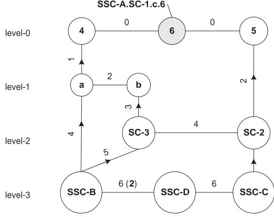
[image:17.612.192.464.77.293.2]SSC-A.SC-1.c.6
Figure 6: The connectivity graph at node 6.
3.2.7 Computing the shortest path
To reach the vertex from any given node, a set of links need to be traversed. This set of links constitutes a path to the vertex node. In the connectivity graph, the best hop to take to reach a certain unit is computed based on the shortest path that exists between the unit and the vertex. This process of calculating the shortest path, from the node to the vertex, starts at the node in question. The directional arrows indicate the links, which comprise a valid path from the node in question to the vertex node. Edges with no imposed directional constraints are bi-directional. For any given node, the only links that come into the picture for computing the shortest path are those that are in the setLU L associated with any of the nodes in a valid path.
The algorithm proceeds by recursively computing the shortest paths to reach the vertex node, along every valid link (LU L) originating at every node that falls within the valid path. Each fork of the recursion keeps track of the nodes that were visited and the total cost associated with the path traversed. This has two useful features
-(a) It allows us to determine if a recursive fork needs to be sent along a certain edge. If we do not keep track of the nodes that were visited, we could end up in an infinite recursion where we revisit the same node over and over again.
(b) It helps us decide on the best edge that could have been taken at the end of every recursive fork.
For example in the connectivity graph of figure 6 we are interested in computing the shortest path to SSC-B from the vertex. This process would start at the node SSC-B. The set of valid links from SSC-B include edges to reach nodesa,SC-3 and SSC-D. At each of these three recursions the paths are reflected to indicate the node traversed (SSC-B) and the cost so far i.e 4,5 and 6 to reacha,SC-3and SSC-Brespectively. Each recursion at every node returns with the shortest path to the vertex. Thus the recursions froma,SC-3 andSSC-D return with the shortest paths to the vertex. This along with the shortest path to reach those nodes, provides us with the means to decide on the shortest path to reach the vertex.
3.2.8 Building and updating the routing cache
3.2 The gateway propagation protocol - GPP 18
This information is collected within therouting cache, so that messages can be disseminated faster throughout the system. The routing cache should be used in tandem with the routing information contained within a routed message to decide on the next best hop to take to ensure efficient dissem-ination. Certain portions of the cache can be invalidated in response to the addition or failures of certain edges in the connectivity graph.
In general when a level-ℓ node is added to the connectivity graph, connectivities pertaining to units at level ℓ, ℓ+ 1,· · ·, N are effected. For a level-N system if a gateway gℓ withinuℓ+1
i is established, the information contained in the routing cache to reach units at levelℓ, ℓ+ 1,· · ·Nneeds to be updated for all the units withinuℓi+1. The cases of gateway failures, node failures, detection of partitions and the updating of the routing cache in response to these failures are dealt with in a later section.
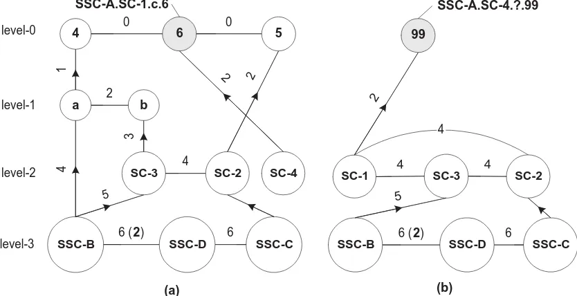
3.2.9 Exchanging information between super-units
When a subsystemuℓ
iis added to an existing systemuℓ+j+1; information regardinggℓ+j, gℓ+j−1,· · ·, gℓ connections are exchanged between the system and the newly added sub system. Thus when a super cluster is added to an existing system comprising of super-super-clusters, the existing system routes information regarding cluster and cluster connections to the newly added super-cluster. The way the set of connections, comprising the connectivity graph, is sent over the newly established link is consistent with the rules, which we had set up for sending a connection informa-tion over a gateway as discussed in secinforma-tion 3.2.3. Thus, if a new super clusterSC-4is added to the
SSC-A sub-system and a super cluster gateway is established betweenSC-4 and nodeSC-1.c.6, then, the connectivity graphs at node6would be as depicted in figure 7.(a) while the connectivity graph at the gatekeeper inSC-4 would comprise of the connections that were sent over the newly established gateway by node6.
6
SC-2
SSC-B
b a
5 4
SSC-C SSC-D
SC-3
6 (2)
4
6 5
4
3
2
1
0 0
2
SC-4 2
(a) SSC-A.SC-1.c.6
6 (2)
SSC-B SSC-D SSC-C
6 SC-2 SC-3
4
5 SC-1
4 4 99
2
(b)
SSC-A.SC-4.?.99
level-0
level-1
level-2
[image:18.612.118.535.386.600.2]level-3
Figure 7: Connectivity graphs after the addition of a new super cluster SC-4.
3.3 Organization of Profiles and the calculation of destinations 19
3.3
Organization of Profiles and the calculation of destinations
Every event conforms to a signature which comprises of an ordered set of attributes{a1, a2,· · ·, an}. The values these attributes can take are dictated and constrained by the type of the attribute. Clients within the system that issues these events, assign values to these attributes. The values these attributes take comprise the content of the event. All clients are not interested in all the content, and are allowed to specify a filter on the content that is being disseminated within the system. Thus a filter allows a client to register its interest in a certain type of content. Of course one can employ multiple filters to signify interest in different types of content. These filters specified by the client constitutes its profile. The organization of these profiles, dictates the efficiency of matching content. A level-ℓ gatekeeper snapshots the profiles of all the level-(ℓ-1) units that share the same GES contextCℓ
i with it.
3.3.1 The problem of computing destinations
Clients express interest in certain types of content, and events which conform to that content need to be routed to the client. A simple approach would be to route all events to all clients, and have the clients discard the content that they are not interested in. This approach would however place a strain on network resources. Under conditions of high load and increasing selectivity by the clients, the number of events a client discards would far exceed the number of events it is actually interested in. This scheme also affects the latency associated with the reception of real time events at the client. The system thus needs to be very selective of the kinds of events that it routes to a client. In other words the system should be able to efficiently compute destination lists associated with the event. Depending on the event this destination list could beinternal to the event orexternal to the event. In the case of events with external destination lists, the system relies on information contained within the client’s profile and also the content of the event to arrive at the set of destinations that need to receive the event.
These destinations should be computed in such a way that it exploits the network topology in place, as also the routing algorithms that make use of abbreviated views of inter-connections existing within the system. Profiles need to be organized so that they lend themselves to very efficient calculation of destinations upon receiving a relevant event. In our approach a level-ℓ gatekeeper maintains the profiles of all the level-(ℓ-1) units that share the same GES contextCℓ
i with it. This scheme fits very well with our routing algorithms, since the destinations contained within the event are those that are consistent with the node’s abbreviated view of the system. To allow for a node to maintain profiles contained at different units (clusters, servers, clients etc.) we need to be able to be able to propagate profile additions and changes to nodes responsible for the generation of destination lists.
The problem of computing destinations for a certain event comprises of the following –
(a) Organization of profiles in a profile graph
(b) Propagation of profiles to the nodes that are responsible for the calculation of hierarchical destination lists.
(c) Navigation of the profile graph to compute the destinations associated with the content.
A given node can compute destinations only at certain level. Thus the computation of destinations is itself a distributed process in our model.
3.3.2 Constructing a profile graph
As mentioned earlier, events encapsulate content in an ordered set of< attribute, value > tuples. The constraints specified in the profiles should maintain this order contained within the event’s signature. Thus to specify a constraint on the second attribute (a2) a constraint should have been
specified on the first attribute (a1). What we mean by constraints, is the specification of the value
3.3 Organization of Profiles and the calculation of destinations 20
within the range permitted by the attribute’s type. By successively specifying constraints on the event’s attributes, a client narrows the content type that it is interested in. It is not necessary that a constraint be specified on all the attributes {a1, a2,· · ·, an}. What is necessary is that if a constraint is imposed on an attributeai constraints for attributesa1, a2,· · ·, ai−1 must be in place,
even if some or all of these constraints is the weakest constraint∗. Thus if a constraint is specified till attributeaiand no constraints are imposed on some of the attributesa1, a2,· · ·, ai−1, the system
assigns these attributes the weakest constraint∗. It makes more sense imposing the constraint∗on higher order attributesai+1· · ·an than on the lower order attributesa1, a2,· · ·ai−1. Such a scheme
has the effect of narrowing content down to the ones which are very closely related to each other. For every event type we maintain a profile chain. Different profile chains when added up constitute the profile graph.
We use the general matching algorithm, presented in [2], of the Gryphon system to organize profiles and compute the destinations associated with the events. Constraints from multiple profiles are organized in the profile graph. Every attribute on which a constraint is specified constitutes a node in the profile graph. When a constraint is specified on an attribute ai, the attributes a1, a2,· · ·, ai−1appear in the profile graph. A profile comprises of constraints on successive attributes
in an event’s signature. The nodes in the profile graph are linked in the order that the constraints have been specified. Any two successive constraints in a profile result in an edge connecting the nodes in the profile graph. Depending on the kinds of profiles that have been specified by clients, there could be multiple edges,originating froma node. Following the scheme in [2] we do not allow multiple edgesterminating at a node since it results in a situation where the event matching results in an invalid destination, due to that event having satisfied partial constraints of different profiles from within the same unit.
s1= {A=a, B=*, C=c} s2= {A=a, B=b,C=c} s3= {A=f, D=d, C=c}
A
C B
C
a
b *
c c
s1 s2
f
D
d
C
c
[image:20.612.244.401.359.570.2]s3
Figure 8: The profile graph - An example.
3.3 Organization of Profiles and the calculation of destinations 21
out of nodeCin figure 8 are destination edges.
3.3.3 Information along the edges
To support hierarchical disseminations and also to keep track of the addition and removal of edges, besides the basic organization of constraints, the graph needs to maintain additional information along its edges. This additional information also plays a very important role in the reliable delivery of events to clients (we discuss this in a later section). Along every edge we maintain information regarding the units that are interested in its traversal. For each of these units we also maintain the number of predicatesδω within that unit that are interested in the traversal of that edge. The first time an edge is created between two constraints as a result of the profile specified by a unit, we add the unit to the route information maintained along the edge. For a new profile ωnew added by a unit, if two of its successive constraints already exist in the profile graph, we simply add the unit to the existing routing information associated with the edge. If the unit already exists in the routing information, we increment the predicate count associated with that destination.
A
B
D C
C
C
a [s1,s2][1,1]
f [s3][1]
d [s3][1] c [s3][1]
b [s2][1]
c [s2][1]
* [s1][1]
c [s2][1]
[image:21.612.203.443.265.429.2]s1= {A=a, B=*, C=c} s2= {A=a, B=b,C=c} s3= {A=f, D=d, C=c}
Figure 9: The complete profile graph with information along edges.
The information regarding the number of predicates δω per unit that are interested in two successive constraints allows us to remove certain edges and nodes from the profile graph, when no clients are interested in the constraints any more. Figure 9 provides a simple example of the information maintained along the edges. We discuss how the profiles are propagated, where they are propagated and how this information along the edges is modified and updated in section 3.3.5.
3.3.4 Computing destinations from the profile graph
Once the profile graph has been constructed, we can compute the destinations that are associated with an event. Traversal along an edge is said to be complete if two successive constraints at end points of the edge have been satisfied by the content in question. When an event comes in we first check to see if the profile graph contains the first attribute contained in the event. If that is the case we can proceed with the matching process. When an event’s content is being matched, the traversal is allowed to proceed only if
-(a) There exists a wildcard (∗) edge connecting the two successive attributes in the event.
(b) The event satisfies the constraint on the first attribute in the edge, and the node that this edge leads into is based on the next attribute contained in the event.
3.3 Organization of Profiles and the calculation of destinations 22
3.3.5 The profile propagation protocol - Propagation of ±δω changes
In the hierarchical dissemination scheme that we have, gatekeepers gℓ+1 compute destination lists
for the uℓ units that it serves as a gℓ+1 for. A gatekeepergℓ+1 should thus maintain information
regarding the profile graphs at each of the uℓ units. Profile graph Pℓ+1
i maintains information contained in profilesPℓ at all theuℓunits withinuℓ+1
i . This should be done so that when an event arrives over agℓ+1 in uℓ+1
i –
(a) The events that are routed to destinationuℓ’s, are those with content such that at least one destination exists for those events within the sub-units that comprise the profile foruℓ. (b) There are no events, that were not routed touℓ
i, with content such that uℓi would have had a destination within the sub-units whose profile it maintains.
Properties (a) and (b) ensure that the events routed to a unit, are those that have at least one client interested in the content contained in the event. When an event is received over a cluster gateway, there would be at least one client attached to one of the nodes in the cluster which is interested in that event.
When we send the profile graph information over to the higher level gatekeepergℓ, the information contained along the edges in the graph needs to be updated to reflect the nodes logical address at that level. Thus when a node propagates the clients profile to the cluster gatekeeper, it propagates the edges created/removed with the server as the destination associated with the profile predicate. Similarly, when this is being propagated to a super-cluster gatekeeper the profile change is sent across as a profile change in the cluster. Any change in the client’s profile is propagated to gatekeepers at higher levels, that the server node in its abbreviated view of the system is aware of. What we are trying to do is to maintain information in the profile graph, in a manner which is consistent with the dissemination constraints imposed by properties (a) and (b). The reason we maintain destination information the way we do is that this model ties in very well with our topology and the routing algorithms that are in place. The connectivity graph provides us with an overall view of the interconnections between units at different levels. The organization and calculation of destinations from the profiles comprising the profile graph, feeds right into our routing algorithms that compute the shortest path to reach the units (destinations) where an event needs to be routed. In general for a level-N system, if there is a subscribing client with GES context CN
j and the issuing client has GES contextCN
i the destinations are computed (N+1) times. Thus, in a system comprising of super-super-clusters, the destinations are computed four times prior to reception at the client.
For profile changes that result in a profile change of the unit, the changes need to be propagated to relevant nodes, that maintain profiles for different levels. A cluster gateway snapshots the profile of all clients attached to any of the server nodes that are a part of that cluster. Thus a change in the profile of a client needs to be propagated to its server node. The change in profile of the server node should in turn be propagated to the cluster gateway(s) within the cluster that the node is a part of. Similarly a super-cluster gateway snapshots the profiles of all the clusters contained in the super-cluster. When a profile change occurs at any level, the updates need to be routed to relevant destinations. The connectivity graph provides us with this information. From the connectivity graph, it can be seen that node 4 is the cluster gateway. Thus, changes in profiles at level-0 (i.e. δω0) at any of the nodes in clusterSSC-A.SC-1.care routed to node 4. δω1 changes need to be
routed to level-2 gateways within SSC-A. In general the gatekeepers to which the profile changes need to be propagated are computed as follows —
(a) Locate the level-(ℓ) node in the connectivity graph.
(b) The uplink from this node of the connectivity graph to any other node in the graph, indicates the presence of a level-ℓ gateway at the unit corresponding to the graph node.
3.3 Organization of Profiles and the calculation of destinations 23
6
SC-2
SSC-B
b a
5 4
SSC-C SSC-D
SC-3
6 (2)
4
6 5
4
3
2
1
0 0
2
level-0
level-1
level-2
level-3
[image:23.612.192.463.77.292.2]SSC-A.SC-1.c.6
Figure 10: The connectivity graph at node 6.
In the figure 10, any δω0 changes at any of the nodes within cluster c, are need to be routed
to node4. Anyδω1 changes at node4need to be routed to node5, and also to a node in cluster b. Similarly δω2 changes at node 5 needs to be routed to the level-3 gatekeeper in cluster a
and superclusters SC-3, SC-2. When such propagations reach any unit/super-unit the process is repeated till such time that the gateway that the node seeks to reach is reached. Every profile change has a unique-id associated it, which aids in ensuring that thereference count scheme does not fail due to delivery of the same profile change multiple times within the same unit.
Summarizing the discussion so far, the profile graph snapshots the profiles of units at a certain level, and as such can compute destinations only for this set of units. The profile snapshot that is created ensures that there is at least one sub-unit attached to one of the units within the super unit under consideration which should receive the event. Thus the profile matching scheme ensures that there is at least one client which will receive the event when it is received within a unit. If we do not have a scheme which snapshots profiles in the following manner, we could end up in a scenario where none of the events received in a unit have any clients which are interested in that event.
3.3.6 Unit additions and the propagation of profiles
When a unit (with publishing and subscribing clients) is being added to a larger existing server network, besides the sequence of actions pertaining to the generation/update of logical addresses and the exchange of system inter connectivities, profiles would need to be propagated in exactly the same way that we described. Thus when a cluster is added to the system, the server nodes within the cluster route their profiles to the newly created cluster gatekeeper. This gatekeeper is in turn responsible for the propagation of profiles to the super-cluster gatekeepers in the newly merged system.
3.3.7 Active profiles