Ames Laboratory Technical Reports
Ames Laboratory
7-1959
Extraction equipment and sampling technique
used in semi-continuous silver-uranium extraction
studies
Edwin H. Olson
Iowa State UniversityMorton Smutz
Iowa State UniversityClayton W. Watson
Iowa State UniversityFollow this and additional works at:
http://lib.dr.iastate.edu/ameslab_isreports
Part of the
Chemical Engineering Commons, and the
Chemistry Commons
This Report is brought to you for free and open access by the Ames Laboratory at Iowa State University Digital Repository. It has been accepted for inclusion in Ames Laboratory Technical Reports by an authorized administrator of Iowa State University Digital Repository. For more information, please [email protected].
Recommended Citation
Olson, Edwin H.; Smutz, Morton; and Watson, Clayton W., "Extraction equipment and sampling technique used in semi-continuous silver-uranium extraction studies" (1959).Ames Laboratory Technical Reports. 2.
Extraction equipment and sampling technique used in semi-continuous
silver-uranium extraction studies
Abstract
Liquid-liquid aqueous extraction methods for reprocessing metallic fuels have two main disadvantages. First, the process involves many steps such as dissolution in acid; extraction, conversion to a salt, and reduction to the metallic state. Secondly, relatively large volumes of radioactive solutions are obtained.
This paper describes small scale, semi-continuous extraction runs for extracting irradiated neodymium from a molten uranium-neodymium alloy using droplets of molten silver at 1250° and 1290°C. Two different silver drop sizes and f 'low .rates were used. The graphite extractor, silver metering device, and the extract sampling equipment are described.
The experimental extraction data obtained are presented. These data were correlated reasonably well with equations developed for multistage batch extractions. The actual neodymium concentrations obtained were compared with equilibrium data to determine extraction efficiencies for the various runs . Extraction efficiencies of 15% to 35% were found, with higher efficiencies resulting when large sized drops were used. In these runs, a considerable amount of neodymium was apparently removed by carbide formation with the container wall prior to the extraction with silver .
Disciplines
Chemical Engineering | Chemistry
EXTRACTION EQUIPMENT AND SAMPLING TECHNIQUE USED IN SEMI-CONTINUOUS SILVER- URANIUM
EXTRACTION STUDIES
by
Edwin H. Olson, Dr. Morton Smutz
UNCLASSIFIED
IS-3
Chemistry-General (UC-4) TID-4500, 1 October 1958 UNITED STATES ATOMIC ENERGY COMMISSION
Research and Development Report EXTRACTION EQUIPMENT AND SAMPLING TECHNIQUE USED IN SEMI-CONTINUOUS SILVER- URANIUM
EXTRACTION STUDIES by
Edwin H. Olson, Dr. Morton Smutz and Clayton W. Watson
July 1959
Ames Laboratory at
Iowa State University of Science and Technology F'. H. Spedding, Director
Contract W-7405 eng-82
UNCLASSIFIED
2
IS-3
This report is distributed according to the category
Chemistry-General, as listed in TID-4500, 1 October 1959.
Legal Notice
This report was prepared as an account of Government sponsored work. Neither the United States, nor the Commission, nor·any person acting
on behalf of the Commission:
A. Makes any warranty of representation, express or·implied,
with· .r.espect to the accuracy, completeness, or usefulness of the information contained in this report, or that the use
of any information, apparatus, method, or process disclosed in this report may not infringe privately owned rights; or B. Assumes. any liabilities with respect to the use of, or for
·damages resulting from the use of any information, apparatus, method, or process tlisclosed in this report.
As used in the above, "person acting on behalf of the Commission" includes any employee or contractor of the Commission, or employee of such contractor, to the extent that such employee or contractor of the Commission, or employee of .such contractor prepares,. dis-seminates, or provides access to, any information pursuant to his employment or contract with the Commission, or his employment with such contractor.
Printed in
USA.
Price$
0. 75 . . Available from the Office of Technical Services3
TABLE OF CONTENTS
Ab:s:tract. . . . . . . . . . . . . . . . . • . . . . • . . . 5
Introduction. . . . . . . . . • . . . 6
Previous Work. . . . • . . . . . . • . . . 7
Equipment .. .. . . o • •.• • • • • • • -..·. • • • • • • • • • • • • • • • • •
9
Experimental Procedure... . . . . . • . . . • . . . 14
Experimental Results. . . • . . . 16
Discussion. . . . . . . . . . . . . . 23
Contri ork was performed in the Ames Laboratory
IS-3
Extraction Equipment and Sampling Technique
Used in Semi-Continuous Silver-Uranium
Extraction Studies
by
5
Edwin H. Olson, Dr. Morton Smutz, and Clayton W. Watson
Institute for Atomic Research and Department of Chemical Engineering
Iowa State University of Science and Technology, Ames, Iowa
Abstract - Liquid-liquid aqueous extraction methods for reprocessing
metallic fuels have two main disadvantages. First, the process involves
many steps such as dissolution in acid; extraction, conversion to a salt,
and reduction to the metallic state. Secondly, relatively large volumes
of radioactive solutions ci're obtained.
This paper describes srmill scale, semi-continuous extraction runs
for extracting irradiated neodymium from a molten uranium-neodymium
alloy using droplets of molten silver at 1250° and 1290°C. Two different
silver drop sizes and f'low .rates were used. The graphite extractor, silver
metering device, and the extract sampling equipment are described.
The experimental extraction data obtained are presented. These
data were correlated reasonably well with equations developed for
6
were compared with equilibrium data to determine extraction efficiencies
for the various runs. Extraction efficiencies of 15% to 35% were found,
with higher efficiencies resulting when large sized drops were used. In
these runs, a considerable amount of neodymium was apparently
removed by carbide formation with the container wall prior to the
extraction with silver.
INTRODUCTION
At the present time, aqueous liquid-liquid extraction processes are
used almost exclusively in the processing of uranium fuels. The
dis-advantages of this method are the loss of the metallic character of the
fuel and the resulting large volumes of waste radioactive solutions to
be handled. Pyroprocessing methods, including oxidative slagging:
distillation, fused salt extraction, fluoride volatility, and liquid metal
extraction, avoid some of these disadvantages. This paper will discuss
the equipment and sampling techniques used in the extraction of uranium
using molten silver. Tracer neodymium was chosen as the element to
represent the rare-earth group of fission products in the extraction
7
PREVIOUS WORK
.l
Preliminary investigations on the distribution of plutonium and fission products in metallurgical operations with irradiated uranium were made by F. H. Spedding, et al, in 1942-1943. A. F. Voigt, (1) in a paper presented at Geneva in 1955, described the work done at the Ames Laboratory from 1950 to 1955, and summarized the status of
silver extraction at that time. The fuels used in this study were irradiated
natural uranium, irradiated uranium-chromium eutectic and specially
prepared mixtures of uranium and selected fission products simulating fuels of 2% burnup. Silver, lanthanum and cerium were the extractants used . . Tantalum and graphite crucibles were used in the extraction runs.
In 1955 D. E. McKenzie (Z) of the Chalk River Project in Canada reported that 60% to 89% of the cerium was extracted from neutron-irradiated uranium using molten silver.
(1) Voigt, A. F., "The Purification of Uranium Reactor Fuel by Liquid-Metal Extraction, 11 Paper No. 545, International Conference on
Peaceful Uses of Atomic Energy, Geneva, Switzerland (July 1955). (2) McKenzie, D. E., "The Extraction of Plutonium from
8
The results of recent work at the Ames Laboratory on the extraction
of cerium and zirconium from cerium-uranium and zirconium-uranium
alloys using molten silver are given by Chiotti and Voigt( 3 ) in a paper
for the second Geneva conference in 1958. Tantalum and tantalum carbide
coated crucibles were used. It was reported that 97o/o to 99. 9o/o of the
cerium was removed when tantalum crucibles were used, with silver
extracting from 66o/o to 93o/o of the cerium. When tantalum carbide coated
crucibles were used they found that 99o/o to 99. 7o/o of the cerium was
removed, but only 40o/o to 60o/o was extracted by the silver. In zirconium
extractions using tantalum crucibles, 90o/o of the zirconium was removed,
but only lOo/o was extracted by the molten silver. They theorized that the
presence of carbon as an impurity probably resulted in side reactions
which were more favorable, thermodynamically, than the extraction of
cerium and zirconium by the silver.
In general, these previous investigations have indicated that fission
products could be divided into several groups of elements exhibiting
(3) Chiotti, P., and Voigt, A. F., 11Pyrometallurgical Processing, 11
Paper P /517, Second United Nations International Conference on
9
similar behavior. Volatile fission products, such as cesium and
strontium were remo¥ed by vaporization. The non-volatile rare
earth metals were readily extracted into silver, while zirconium and
tellurium constituted a non-volatile group which was less readily
extracted by the silver. Ruthenium and molybdenum remained almost
completely with the uranium. Plutonium was found to extract readily
into the silver"
Most of the previous investigations have been batch-wise extractions.
Littf.-e work has been directed towards the development of contacting
equipment, processing techniques, or the study of operating conditions
for continuous or semi-continuous extractions.
EQUIPMENT
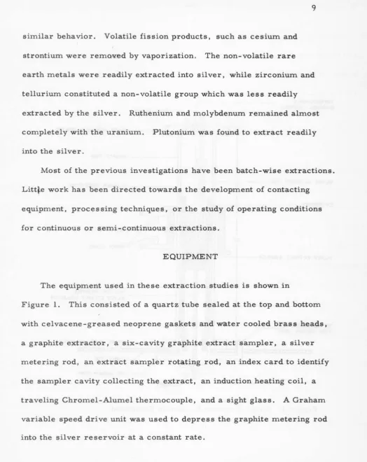
The equipment used in these extraction studies is shown in
Figure 1. This consisted of a quartz tube sealed at the top and bottom
with celvacene-greased neoprene gaskets and water cooled brass heads,
a graphite extractor, a six-cavity graphite extract sampler, a silver
metering rod, an extract sampler rotating rod, an index card to identify
the sampler cavity collecting the extract, an induction heating coil, a
traveling Chromel-Alumel thermocouple, and a sight glass. A Graham
variable speed drive unit was used to depress the graphite metering rod
[image:12.602.56.580.54.714.2]THERMOCOUPLE (CHROMEL- ALUMEL)
SILVER METERING R O D - - - 1 -- --f
TO THERMOCOUPLE TYPE VACUUM G"AGE
-10-SIGHT GLASS
I - - - B R A S S HEAD (H 20 COOLED)
I -- - - ----QUARTZ TUBE
~---ALUNDUM INSULATION
POWER LEADS
ROD FOR ROTATING
r;+...-ti4f H - - - -SILVER EXTRACT COLLECTOR
TABLE TOP
TO VACUUM PUMP
INDEX
ll
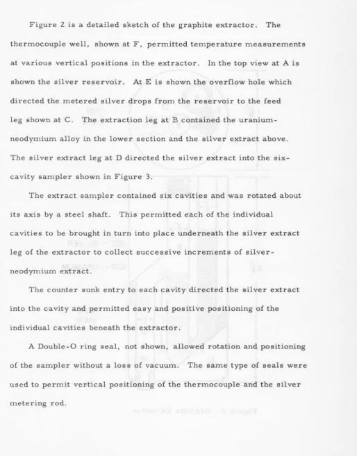
Figure 2 is a detailed sketch of the graphite extractor. The
thermocouple well, shown at F, permitted temperature measurements
at various vertical positions in the extractor. In the top view at A is
shown the silver reservoir. AtE is shown the overflow hole which
directed the metered silver drops from the reservoir to the feed
leg shown at C. The extraction leg at B contained the
uranium-neodymium alloy in the lower section and the silver extract above.
The silver extract leg at D directed the silver extract into the
six-cavity sampler shown in Figure 3.
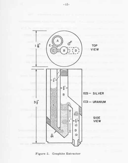
The extract sampler contained six cavities and was rotated about
its axis by a steel shaft. This permitted each of the individual
cavities to be brought in turn into place underneath the silver extract
leg of the extractor to collect successive increments of
silver-neodymium extract.
The counter sunk entry to each cavity directed the silver extract
into the cavity and permitted easy and positive positioning of the
individual cavities beneath the extractor.
A Double-0 ring seal, not shown, allowed rotation and positioning
of the sampler without a loss of vacuum. The same type of seals were
used to permit vertical positioning of the thermocouple and the silver
[image:14.602.78.593.69.727.2]Figure 2.
-1
2-. Extractor Graph1te
TOP
VIEW
~-SILVER
""
'"
i l -
URANIUM
[image:15.605.18.538.48.705.2]- 1
3-COUNTERSUNK ENTRY
SILVER EXTRACT
CAVITIES-
~·
DIAM.~=::::::::---~
211
GRAPHITE
COLLECTOR - - + - - t
SAMPLER
I
,, I
I lu
:: : :
:f
{~·~·B]
:
~r-+--+--SJLVER
EXTRACTII 11 I
~~
~;~·
3"
II I
I~V'~
14II I I r.'~ ·
II 1 1 lfr.'l
I , .... _ .... r - - ,.,,t~l;~· '-:'-,~1':
,
.. _ .. I...
-
..
:,
I ~.· .... - -.J
THREADED CONNECTION
.,
.
~-rl -F-J~((cr.~
..
~@
.
,
-...
,
t -
1-
I"
- 1 - - + - - - tr-:-· 2
~----STEEL
SHAFTcy
TO DOUBLE
'o'
RING VACUUM [image:16.604.76.570.57.729.2]. SEAL IN BOTTOM BRASS HEAD OF VACUUM SYSTEM
14
A General Electric type TG-029 thermocouple vacuum guage
was used to measure the pressure in this system.
EXPERIMENTAL PROCEDURE
The uranium-neodymium alloy was prepared by melting the two
metals in a tantalum crucible, followed by casting into a 5 cavity
graphite mold at 1220°C. This gave rods 5/16 inch in diameter
and 3 inches in length, suitable for use in extraction runs. The
graphite was cracked away from each of the 5 rods, the rods
electroche1r1ically cleaned using a glycerol-water-sulfuric acid
solution, and top, n'1iddle, and bottom samples removed for
radio-chemical analysis for neodymium .
The following procedure was used in a typical extraction run. The
vacuum system, with all components in place, was degassed to
approximately 50 microns of mercury absolute pressure at 1300°C
and then cooled to room temperature. The system was opened to the
atmosphere, silver and the uranium-neodymium alloy were charged to
the extractor, the system was reassembled, re-evacuated and heated
to the extraction temperature of either 1250 or 1290°C. Molten
silver was then metered dropwise into the silver feed leg from the
15
silver had been added to the feed leg to overcome the static pressure
head of the uranium-neodymium alloy in the extraction leg, each additional
drop of silver metered to the feed leg resulted in a drop of silver of the
same size being forced into the extraction leg. The silver droplet in
the extraction leg then flowed upward through the uranium-neodymium
alloy to the extract overflow leg. Simultaneous with the entry of a
silver droplet to the extraction leg, an equal weight of silver was
displaced from the top of the extraction leg into the extract overflow leg
which directed it into the extract sampler.
After the desired number of silver drops, visually counted, had
been meterec\ the extract sampler was rotated to bring the next cavity
into position to receive the next increment of extract. This procedure
was continued until the maximum amount of silver possible had been
metered from the silver reservoir. The graphite metering rod was
then raised from the silver reservoir, the power to the induction coil
was turned off and the system cooled to room temperature under vacuum.
The extractor and extract sampler were removed from the system
and the graphite was sawed and cracked away from the uranium and
silver phases. The uranium phase was electrochemically cleaned, the
16
silver-uranium interface, and the whole uranium phase was submitted for neodymium analysis. The individual silver extract slugs from the
sampler were submitted for neodymium analysis.
A total of 8 extraction runs wta·.S! made. Temperatures of approximately
1250° and 1290°C, silver drop sizes of approximately 1. 6 and 2. 4 grams
and two different diameter graphite metering rods were used. The silver drop size was found in preliminary non-extraction runs to be dependent upon the diameter of the metering rod, with the smaller rod diameters
resulting in larger drop sizes. The rod diameters used in the extraction
runs were;3/8 and 15/32 inches.
EXPERIMENTAL RESULTS
As mentioned previously, a top, middle, and bottom sample of each
of the uranium-neodymium alloy rods wta.~ taken for neodymium
analysis. This left two cylindrical alloy slugs per rod for use in the
extraction runs. The neodymium analyses of the top, middle, and
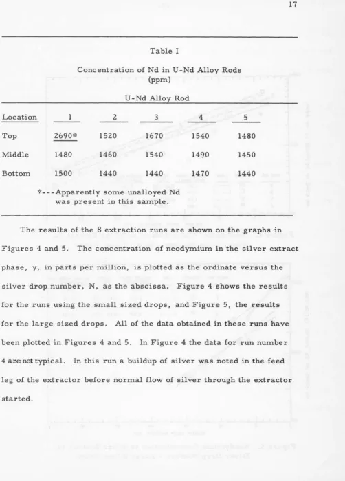
bottom samples for each aUoy rod are shown in Table .I.
It will be noted that the neodymium concentration was generally quite
uniform except for the top sample from rod number 1. Due to the much
higher neodymium concentration, the top extraction slug from rod number
Location
Top
Middle
Bottom
Table I
Concentration of Nd in U -Nd Alloy Rods (ppm)
U -Nd Alloy Rod
1 2 3 4 5
269o~:c 1520 1670 1540 1480
1480 1460 1540 1490 1450
1500 1440 1440 1470 1440
~:c---Apparently some unalloyed Nd was present in this sample.
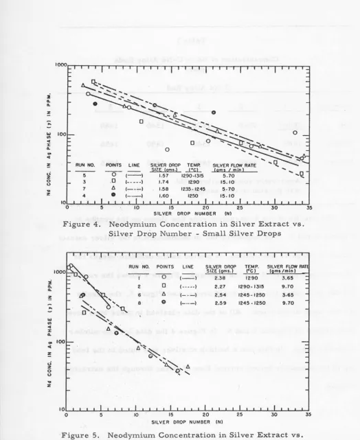
The results of the 8 extraction runs are shown on the graphs in 17
Figures 4 and 5. The concentration df neodymium in the silver extract
phase, y, in parts per million, is plotted as the ordinate versus the
silver drop number, N, as the abscissa. Figure 4 shows the results
for the runs using the small sized drops, and Figure 5, the results
for the large sized drops. All of the data obtained in these runs have
been plotted in Figures 4 and 5. In Figure 4 the data for run number
4 axetDdt typical. In this run a buildup of silver was noted in the feed
leg of the extractor before normal flow of silver through the extractor
[image:20.606.86.589.59.760.2]:i a. a.
...
w Ill c( :J: a..,.
c( ~0 z 0 0
..,
z :i Q. Q. ~...
w Ill c( :J: a..,.
c( ! 0 z 0 0..,
z- 1
8-0
RUN NO. POINTS LINE SILVER DROP TEMP. SILVER FLOW RATE
( ) lNE (gms.} ~ (gro~ l mjn l
5 (- - ) 1.57 1290-1315 5.70
3 .0 (---) 1.74 1290 15.10
7 6 1.58 1235-1245 5·70
10=-L-~~~~~~~~~-L-L-L-L~~~~~~L-L-~~LJ~~~-L-L-L-LJ
0 15 20 25 30
SILVER DROP NUMBER (Nl
Figure 4. Neodymium Concentration in Silver Extract vs.
Silver Drop Number - Small Silver Drops
RUN NO. POINTS LINE SILVER DROP TEMP. SILVER FLOW RAT
- - -
SIZE 12ms.) ~ ( ms/mln)( ) (- - ) 2.38 1290 3,65
2 0 (---) 2.27 1290- I 315 9.70
6 6 ( --- ) 2.54 1245-1250 3·65
8 0 (---- ) 2.59 1245-1250 9.70
10
0 15 35
SILVER DROP NUMBER (N)
Figure 5. Neodymium Concentration in Silver Extract vs.
[image:21.597.8.532.66.707.2]It was noted that straight lines gave a fairly good representation
of the data. This would be expected if:
l. The extraction method were considered to be a multistage
cocurrent batch extraction where each successive drop of silver
represents one stage.
2. The silver drops were all of the same size.
3. The actual distribution coefficient for neodymium between
uranium and silver remained constant throughout the individual runs.
4. The weight ratio of the silver drop to the uranium phase also
remained constant.
5.
The neodymium was uniformly distributed throughout theuranium.
If neodymium material balances are taken after each successive
drop of silver extract has been collected, it can be shown that Equation
1 describes the extraction process, provided the five conditions just
given are closely approximated.
( xo)
<Ka)
Y(N)
=
(1 +RKa)N
where: y(N) =average concentration of neodymium in silver
extract drop number N.
x0
=
original concentration of neodymium in theuranium-neodymium alloy before extraction.
( 1)
20
Ka = actual distribution coefficient for neodymium between silver
and uranium. (The concentration of neodymium in the silver
extract drop divided by the neodymium concentration in the
uranium phase after the droplet of silver has passed through .. )
R =weight ratio of the silver drop to the uranium phase.
Taking logarithms of both sides of Equation 1 gives Equation 2:
Log y(N) = (Log x0 +Log Ka) + N [-Log (1 + RKa)] .
Therefore, Equation 2 is a straight line if the logarithm of y(N) is
plotted versus N; since "'-Log ( 1 + RKa) is the slope of the line and is
a constant.
If the experimental ~ata could be satisfactorily represented by
Equation 2, it would be possible to measure the slope of the lines of
the various runs .and evaluate ~a since the value of R is known. The
values of Ka could 'then .be compared with the equilibrium distribution
coefficient for neod)rrpiul'!l between silver and uranium to determine an
extraction efficiency .for each of the runs. The only difficulty that
arises is that exact equilibriu~ distribution data for neodymium is
"1 bl . . . . . k . . 1 ( 4 ) h. L b
not a va1 a e. However, wor by Vo1gt, et a . at t 1s a oratory
{2)
(4) Voigt, A. F., Daane,· A. H., Dewell, E. H. Clark, R. G., Gonser,
J. E. , Haefling, J.
F.
and Mala by, K. L. , "Liquid Metal Extraction21
indicated that at 1200 o to 1220 o C the equilibrium distribution
coefficient for neodymium between silver and uranium is in the 3
to 30 range. The current authors, using graphite crucibles, obtained
distribution ~oefficients of approximately 8 and 12 in the temperature
range from 1220° to 1270°C.
Assuming an equilibrium distribution coefficient of 10, the
extraction efficiencies for the various runs were calculated by
dividing the actual distribution coefficients by the assumed equilibrium
distribution coefficient of 10. The values of Ka and the extraction
efficiencies for the series of extraction runs made in this inve~tigation
are given in Table II along with the extraction temperature, silver
drop size, and silver flow rate.
It will be noted that the use of large sized drops of silver resulted
in higher actual distribution coefficients and extraction efficiencies
than the use of small sized drops. It was expected that the smaller
I
drops, with their greater surface area per given amount of silver,
would be more effective in extracting the neodymium than the large
drops. However, it was found that the large sized drops, if spherical,
would have a diameter of approximately 0. 31 inches. This is quite
close to the 0. 375 inch diameter of the extraction leg of the extractor.
22
Run No.1
2
6
8
5
3
7
4):c
Table II
Actual Neodymium Distribution Coefficients and Extraction Efficiencies For Various Extraction Conditions
Temperature Silver Drop Silver Flow Rate Ka Efficiency
( oc) Size (grams) (grams/min. )
Large Sized Silver Drops
1290
2
.
38-
3
.
65
3.51
1290-1315
2.27
9.70
2.45
1245-1250
2.54
3.65
l.83
1245-1250
2.59
9.70
2. 10
Small Sized Silver Drops
1290-1315
l.57
5.70
1.45
1290
L 74
15. 10
1.68
1235-1245
l.58
5.70
1.50
1250
l.60
15
.
10
1.35*
*
This run not normal. Excess head of silver built up in the feed leg of the extractor before normal flow occurred.( o/o)
35
.
1
24
.
5
18
.
3
21. 0
14.5
16.8
15. 0
drops through the uranium-neodymium alloy, thus permitting a
greater contact time for neodymium extraction by the silver. The
wall effect would also cause a higher velocity of flow of the uranium
phase around the silver drop, resulting in a higher extraction rate.
One non-extraction run at 1290°C was made whereby the
uranium-neodymium alloy alone was melted in a graphite extractor. The
removal of the carbide slag from the uranium by electrochemical
cleaning showed approximately 50 per cent loss of the neodymium,
along with a 1. 5 per cent loss of uranium.
DISCUSSION
The extraction equipment and its operation were quite satisfactory.
23
The large amounts of neodymium removed by carbide slagging indicates
the need for a more inert material of construction for the extractor in
order to eliminate carbide slagging as a possible variable affecting
the silver extraction of rare earths from uranium.
The extraction efficiencies, assuming the equilibrium coefficient to
be approximate! y 10, showed the large sized silver drops to be more
effective in extracting neodymium than the small ones. As previously
mentioned, this was probably due to the increased contact time of the
24
contacting efficiency due to higher uranium velocities around the larger
drops. On this basis there is a need for better agitation and mixing if
a high actual neodymium distribution coefficient and resulting efficiency
are to be obtained.
The effects of temperature and silver flow rate on extraction
efficiency were found to be minor compared to the silver drop size.
It is possible that this method of extraction could be converted to
an intermittent stagewise countercurrent method by vertically stacking
several extraction units. The silver extract from the top unit would
be directed to the next unit below where more neodymium would be
extracted. The extract from this unit would extract more neodymium
from the third unit, and so on, with the silver-neodymium extract
finally being collected from the bottom unit in the stack. After passing
a given amount of silver through the series of stacked extractors, the
top extractor would be removed, a new unit placed at the bottom and
the cycle repeated. This would give a stage-wise countercurrent flow
of the silver through the various extraction units which would result
in a more efficient use of the silver, lower loss of uranium and higher