International Journal of Innovative Technology and Exploring Engineering (IJITEE)
ISSN: 2278-3075,
Volume-8 Issue-12, October, 2019
Abstract: Many Discrete Wavelet Transform (DWT) based VLSI architectures have been projected to meet the necessities of the synchronized signal processing. It includes image processing, speech processing, signal and video processing, etc. The practical implementation of DWT has fewer hitches in terms of hardware complexity and memory requirement since it needs to process huge volume of data. The traditional convolution based system needs more multipliers and larger memory and is also not suitable to provide speed or power efficient image or video processing designs. The lifting scheme involves very few mathematical computations compared to the convolution-based DWT. In this paper, we propose an architecture that performs Discrete Wavelet Transform (DWT) using a lifting-based scheme with fine grained pipelined architecture. The basic DWT filters used in image compression are 5/3(lossless) and 9/7(lossy) filters. In fine grain pipelining, multiplier is split into two units by placing the latches on the horizontal cutset across the multiplier. Thus the critical path is reduced to half of the multiplier delay. As a result, it is a speed efficient architecture and is symmetrical with a lower hardware complexity. The architecture is designed using verilog HDL and implemented on Xilinx Spartan 3E FPGA.
Keywords: DWT, lifting scheme, 5/3 filter, 9/7filter, fine grain pipelining.
I.
INTRODUCTION
Conversion of an image into digital representation
and execution of some operations for the enhancement of the
image and extraction of some useful information from that is
possible with image processing. The source of input may be
image or video frame or photograph and output may be image
or it may have the associated characteristics. Image
processing system treats images as two dimensional signals
and processes them to obtain some significant data from an
image. Image compression is one of the significant image
processing techniques and is dropping the bytes of a graphics
file size without corrupting the excellence of the image to a
disagreeable level. The fall in file size permits more images to
be accommodated in storage with the specified quantity of
disk space or memory space. It furthermore diminishes the
time needed for images to be sent and there are numerous
methods in which image files can be compressed. The
intention of image compression is to decrease insignificance
Revised Manuscript Received on October 10, 2019 * Correspondence Author
Anbumani V, Assistant Professor, Department of ECE, Kongu
Engineering College, Perundurai Erode-638052, Tamilnadu, India
Geetha V, Assistant Professor, Department of ECE, Kongu Engineering
College, Perundurai Erode-638052, Tamilnadu, India
Murugesan G, Professor and Head, Department of ECE, Kongu
Engineering College, Perundurai Erode-638052, Tamilnadu, India
and redundancy of the image data to facilitate storage
or transmission of data in a well-organized form. Thus
redundancy could be spatial, spectral or temporal
redundancy. The correlation between the neighboring pixels
provides spatial redundancy, the correlation among dissimilar
color planes provides spectral redundancy and the correlation
of order of image of different frames such as in video
conferencing application provides temporal redundancy. The
image compression techniques are commonly categorized
into lossless and lossy depending whether or not an accurate
model of the original image could be remodelled using the
compressed form of image. Medical imaging desires lossless
compression which is used only for a few uses with rigid
requirements .Lossy compression technique aims to achieve
high compression ratio by letting some adequate degradation
in the image. Wavelets and filter banks have been used
independently in image compression and signal processing.
Fourier Transform (FT) cannot be used for the analysis of
non-stationary signals which provides only the existence
frequency components. Whereas Discrete Cosine Transform
(DCT) gives the timing information and is a significant
transform in 2D signal processing. Since DCT function is
fixed and it cannot be adapted to source data there is
undesirable blocking artifacts. Also DCT is block based and it
neglects the pixels of the neighboring blocks and it is difficult
to entirely decorrelate the blocks at their boundaries.
Therefore, Discrete Wavelet Transform (DWT)is chosen for
the proficient image compression standard JPEG2000.The
data is decomposed into components of different frequencies
which has both time and frequency components. By low pass
and high pass filter analysis, the image is filtered initially
through x axis and later the image is filtered in y dimension.
Finally image is split into four sub bands namely HH, HL, LL,
and LH. The present VLSI 2-D DWT architectures be able to
classify into convolution-based designs [3]–[11] and
lifting-based designs [12]–[32]. Few architectures sort from
greatly parallel to programmable DSP-based architectures to
folded architectures [16] and [17]. Among this, FIR filter
banks are used in the implementation of convolution based
architectures whereas factorizing the filter banks into more
than a few lifting steps is adapted in the implementation of the
lifting-based architectures [28]. These architectures consist of
strong arithmetic resource like multipliers, weak arithmetic
resource like adders, few multiplexers, and minimum memory
requirement. Reduction in computational complexity and
increase in memory efficiency with increase in critical path is
the net result with the lifting architectures.
Implementation of Efficient Architecture of
Fine Grain Pipelined Lifting Scheme Based
Two Dimensional Discrete Wavelet Transform
Dimensional Discrete Wavelet Transform
To diminish the critical path of the lifting scheme
flipping method is planned by Huang et al. [13].To reduce the
memory requirement many data scanning techniques have
been proposed namely line-based designs, modified version
of line-based designs, block-based designs and stripe-based
designs.
The remaining sections of the paper are planned as
follows: Section II analyses the mathematical grounds of the
lifting design and the structure of 5/3 filter and 9/7 filter.
Then, Section III describes the proposed fine grain method for
2D DWT architectures with 5/3 filter and 9/7 filter. Section
IV analyses the performance of the intended design and the
multiplier based architectures and in the end Section V
concludes the work.
II.
THE BASIC CONSTRUCTION OF LIFTING SCHEME
SUBMISSION OF THE PAPER
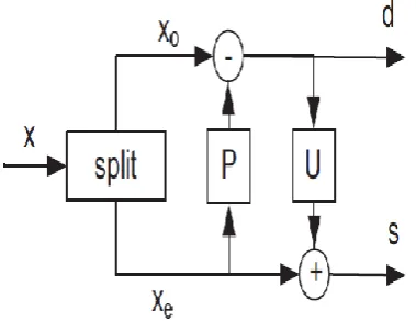
The essential steps in lifting scheme includes, Split step
followed by Predict step and finally Update step. The basic
construction of lifting scheme is given in Fig 1.
Fig 1. The Basic Construction of Lifting Scheme
In the split stage, signal splits into two disjoint sets of samples
namely even indexed samples
and odd indexed samples
. This is shown in equation (1) and (2),
=
(1)
=
(2)
In the predict stage, the even subsets and odd subsets are
combined. If the signal has local correlation plan, then the
even subsets and odd subsets will be greatly related. This is
shown in equation (3),
=
+α×( +
) (3)
In the update stage, the detailed samples will be restructured
to the even sample. This is shown in equation (4),
=
+β×(
+
) (4)
A.
Basic Structure of 5/3 Filter
There are five taps in the low pass filter is and three taps in the
high pass filter and hence it is (5, 3) filter. The basic structure
of 5/3 filter is given in Fig 2.
. Fig 2. The Basic Structure of 5/3 Filter
B.
Basic Structure of 5/3 Filter
[image:2.595.307.537.271.410.2]There are 9 taps in the low pass filter is and 7 taps in the high
pass filter and hence it is (9, 7) filter. The basic construction
of 9/7 filter is given in Fig 3.
Fig 3. The Basic Construction of 9/7 Filter
III.
FINE GRAIN PIPELINING
Fine grain pipelining is a pipelining technique
applied on multipliers. By placing the latches on the
horizontal cutset across the multiplier, the architecture can be
modified with the reduced critical path. Hence the desired
speed can be achieved.
A.
Splitting methodology
Multiplier should be split such that minimum
hardware should be used by each multiplier during
implementation. Hence it should be power of 2.Considering
the coefficient of the multiplier is 0.03125, it should be split
such that m1= 0.125 and m2=0.25.By doing fine grain
pipelining on the multipliers, the architecture is with the
minimized critical path of (T
m)/ 2, where T
mis the multiplier
delay.
[image:2.595.58.248.306.453.2]B.
Split Coefficients of 5/3 Filter
Table 1. Split coefficients of 5/3 filter.
Coefficient In powers
of 2
Split
coefficients in powers of 2
Binary Representation of split coefficients
-0.5 -1 -0.5 &-0.5 10111010 10111010
International Journal of Innovative Technology and Exploring Engineering (IJITEE)
ISSN: 2278-3075,
Volume-8 Issue-12, October, 2019
C.Modified 5/3 Filter
[image:3.595.56.272.113.279.2]The modified structure of 5/3 filter using fine grain
pipelining is given in Fig 4. In Fig.4 M
1, M
2, M
3and M
4are
the split fine grain computational units of the multiplier in the
conventional system.
Fig 4. Modified structure of 5/3 filter
D.Split Coefficients of 9/7 Filter
The coefficients of 9/7 filter are
α
= 1.586134342,
β=−0.052980118,
γ=0.8829110762,
and
δ=0.4435068522.The coefficients are split based on the
power of 2.Split coefficients of 9/7 filter by fine grain
pipelining is given in table 2.
Table 2.Split coefficients of 5/3 filter
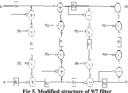
E.Modified 9/7 Filter
The modified structure of 9/7 filter using fine grain
pipelining is given in Fig 5. In Fig.5 M
1, M
2, M
3,M
4,M
5, M
6,
M
7and M
8are the split fine grain computational units of the
multiplier in the conventional system.
Fig 5. Modified structure of 9/7 filter
IV.
RESULT AND DISCUSSION
A. Comparison of Hardware Complexity
The hardware requirement for the implementation of
conventional 2D DWT design with convolution scheme and
lifting scheme based 2D DWT are reviewed in terms of
multipliers/ shifters and adders essential for implementation.
The Table.3 shows the number of multiplication operations,
addition operations and shift operations necessary for (5, 3)
and (9, 7) for both convolution and lifting methods.
Table 3. Hardware requirement for convolution and
lifting 2D DWT [8]
From the Table.3, the lifting scheme will be more
appropriate for hardware implementation of DWT with lesser
computational intricacy, less area and minimized power. With
the intention of showing enhancement in the speed of
processing, utilization of fine-grain pipelining has been
planned. By using this method, the multiplier unit present in
the critical path of the circuit is broken into finer pieces.
[image:3.595.307.550.178.279.2]B.
Performance Comparison of 2D DWT 5/3 Filter
The 2D DWT lifting scheme based 5/3 and 9/7 filter
structures and fine grain pipelined architectures were
designed using verilog HDL and implemented on Xilinx
Spartan 3E FPGA. The power and delay of the conventional
2 D DWT lifting scheme and the fine grain pipelined
architecture of 2D DWT architectures were given in Table 4.
Table 4.Comparison of power and delay of the 2D DWT
with 5/3 filter using conventional and fine grain pipelined
techniques
The power reduction of 29.67 % and delay reduction
of 11.55% is achievable with the fine grain pipelined design
and the conventional design of 2D DWT architecture with 5/3
filter.
C.
Performance Comparison of 2D DWT 9/7 Filter
Table 4.Comparison of power and delay of the 2D DWT
with 5/3 filter using conventional and fine grain pipelined
techniques
Coefficient
In powers of
2
Split
coefficients in
powers of 2
Binary
Representation of split coefficients 1.58 0.6599 -0.09&-0.74
99
01011101& 10101000
0.05 -4.321 9
-0.09&-4.23 19
01011101& 11111011
0.88 -0.184 4
-0.09&-0.09 01011101& 01011101
0.44 -1.184 4
-0.09&-1.09 01011101& 00101110
Filter
Multiplication/Shifts Additions
Convolutio n
Liftin g
Convoluti on
Lifti ng (5,3)
Lossless 4 2 6 4
(9,7)
Lossy 9 5 14 8
Name of the 2D DWT lifting architecture
Power (µW)
Delay(nS)
Using conventional
technique 393.57 15.32
Using fine grain pipelined
technique 276.80 13.55
Name of the 2D DWT lifting architecture
Power (µW)
Delay(n S)
Using conventional technique 769.09 22.56
Using fine grain pipelined technique
[image:3.595.50.276.602.765.2]Dimensional Discrete Wavelet Transform
The performance comparison of fine grain pipelined design
and the conventional design of 2D DWT architecture with 9/7
filter shows the power reduction of 33.97 % and delay
reduction of 29.06% .
V.
CONCLUSION
High speed architecture for lifting based 2D DWT
using fine grain pipelining is proposed.
In this method, the critical path is reduced to Tm/2
and hence the speed of the architecture is increased. The
modified lifting algorithm has a minimum critical path. Hence
the fine grain pipelined architecture has a good hardware
efficiency, lower complexity and increased speed.
REFERENCES
1.
S. G. Mallat, “A theory for multiresolution signal decomposition: thewavelet representation,” IEEE Trans. Pattern Anal. Mach. Intell., vol.11, pp. 674–693, 1989.2. R. Majid and J. Rajan, “An overview of the JPEG 2000 still imagecompression standard,” Signal Process., Image Commun., vol. 17, pp.3–48.
3. K. K. Parhi and T. Nishitani, “VLSI architectures for discrete wavelettransforms,” IEEE Trans. Very Large Scale Integration (VLSI) Syst.,vol. 1, no. 2, pp. 191–202, 1993.
4. M. Vishwanath, R.M. Owens, andM. J. Irwin, “VLSI architectures forthe discrete wavelet transform,” IEEE Trans. Circuits Syst. II, AnalogDigit. Signal Process., vol. 42, no. 5, pp. 305–316, 1995. 5. F. Marino, “Efficient high-speed/low-power pipelined architecture
forthe direct 2-D discrete wavelet transform,” IEEE Trans. Circuits Syst.II, Analog Digit. Signal Process., vol. 47, no. 12, pp. 1476–1491, 2000.
6. F. Marino, “Two fast architectures for the direct 2-D discrete wavelettransform,” IEEE Trans. Signal Process., vol. 49, no. 6, pp. 1248–1259,2001.
7. P.-C. Wu and L.-G. Chen, “An efficient architecture for two-dimensional discrete wavelet transform,” IEEE Trans. Circuits Syst. Video Technol., vol. 11, no. 4, pp. 536–545, 2001.
8. P. K. Meher, B. K. Mohanty, and J. C. Patra, “Hardware-efficient systolic-like modular design for two-dimensional discrete wavelet transform,”IEEE Trans. Circuits Syst. II, Express Briefs, vol. 55, no. 2, pp.151–155, 2008.
9. C. Zhang, C. Wang, and M. O. Ahmad, “A pipeline VLSI architecturefor fast computation of the 2-D discrete wavelet transform,” IEEETrans. Circuits Syst. I: Reg. Papers, vol. 59, no. 8, pp. 1775–1785,2012.
10. C. Cheng and K. K. Parhi, “High-speed VLSI implementation of 2-Ddiscrete wavelet transform,” IEEE Trans. Signal Process., vol. 56, no.1, pp. 393–403, 2008.
11. B. K. Mohanty and P. K. Meher, “Memory-efficient high-speed convolution-based generic structure for multilevel 2-D DWT,” IEEE Trans.Circuits Syst. Video Technol., vol. 23, no. 2, pp. 353–363, 2012. 12. K. Andra, C. Chakrabarti, and T. Acharya, “A VLSI architecture forlifting-based forward and inverse wavelet transform,” IEEE Trans.Signal Process., vol. 50, no. 4, pp. 966–977, 2002.
13. C.-T. Huang, P.-C.Tseng, and L.-G. Chen, “Flipping structure: An efficientVLSI architecture for lifting-based discrete wavelet transform,”IEEE Trans. Signal Process., vol. 52, no. 4, pp. 1080–1089, 2004.
14. V.Geetha and G.Murugesan, “Performance Analysis of Horner’s Rule Based Canonical Signed Digit Lifting Architecture for Two Dimensional Discrete Wavelet Transform”, International Journal of Biomedical Engineering and Technology, vol. 23, no. 2/3/4, pp. 123-136, 2017.
15. V.Geetha and G.Murugesan, “High performance VLSI architecture to improve contrast in digital mammographies using discrete wavelet transform”, Biomedical Research – India 2017, Special Section: Artificial Intelligent Techniques for Bio-Medical Signal Processing,Special Issue: pp. S141-S146, 2017. DOI:10.1504/IJBET.2017.082654
16. S Sasikala, and G Murugesan, ,"Efficient Digit Serial Architecture for Sign Least Mean Square Adaptive Filter for Denoising of Artifacts in ECG Signals", International Journal of Biomedical Engineering and
DOI:10.1504/IJBET.2017.082672
17. M Jayapravintha , S Gomathi and G Murugesan.,"Design Of Systolic Architecture For Various Adaptive Filters For Noise Cancellation",Proceedings of 3rd International Conference on Signal Processing, Communication and Networking, August 2015 DOI: 10.1109/ICSCN.2015.7219907
18. H.-Y. Liao, M. K. Mandal, and B. F. Cockburn, “Efficient architecturesfor 1-D and 2-D lifting-based wavelet transforms,” IEEE Trans. SignalProcess., vol. 52, no. 5, pp. 1315–1326, 2004.
19. C.-T. Huang, P.-C.Tseng, and L.-G. Chen, “Generic ram-based architecturesfor two-dimensional discrete wavelet transform with linebasedmethod,” IEEE Trans. Circuits Syst. Video Technol., vol. 15, no.7, pp. 910–920, 2005.
20. B.-F.Wu and C.-F. Chung, “A high-performance andmemory-efficientpipeline architecture for the 5/3 and 9/7 discrete wavelet transform ofJPEG2000 codec,” IEEE Trans. Circuits Syst. Video Technol., vol. 15,no. 12, pp. 1615–1628, 2005.
21. C.-Y. Xiong, J. Tian, and J. Liu, “Efficient high-speed/low-powerline-based architecture for two-dimensional discrete wavelet transformusing lifting scheme,” IEEE Trans. Circuits Syst. Video Technol., vol.16, no. 2, pp. 309–316, 2006.
22. C.-Y.Xiong, J. Tian, and J. Liu, “Efficient architectures for two-dimensionaldiscrete wavelet transform using lifting scheme,” IEEE Trans.Image Process., vol. 16, no. 3, pp. 607–614, 2007. 23. Y.-K. Lai, L.-F.Lien, and Y.-C. Shih, “A high-performance
andmemory-efficient VLSI architecture with parallel scanning method for2-D lifting-based discrete wavelet transform,” IEEE Trans. Consum.Electron., vol. 55, no. 2, pp. 400–407, 2009.
24. B. K. Mohanty and P. K. Meher, “Memory efficient modular VLSI architecturefor highthroughput and low-latency implementation of multilevellifting 2-D DWT,” IEEE Trans. Signal Process., vol. 59, no. 5,pp. 2072–2084, 2011.
25. B. K. Mohanty, A. Mahajan, and P. K. Meher, “Area- and power-efficientarchitecture for high-throughput implementation of lifting 2-DDWT,” IEEE Trans. Circuits Syst. II, Express Briefs, vol. 59, no. 7, pp.434–438, 2012.
26. X. Tian, L. Wu, Y.-H.Tan, and J.-W. Tian, “Efficient multi-input/multi-output VLSI architecture for two-dimensional lifting-based discretewavelet transform,” IEEE Trans. Comput., vol. 60, no. 8, pp.1207–1211, 2011.
27. W. Zhang, Z. Jiang, Z. Gao, and Y. Liu, “An efficient VLSI architecturefor lifting-based discrete wavelet transform,” IEEE Trans. CircuitsSyst. II: Expr. Briefs, vol. 59, no. 3, pp. 158–162, 2012. 28. I. Daubechies and W. Sweldens, “Factoring wavelet transforms
intolifting steps,” J. Fourier Anal. Appl., vol. 4, pp. 247–269, 1998. 29. C. Chrysafis and A. Ortega, “Line-based, reduced memory,
waveletimage compression,” IEEE Trans. Image Process., vol. 9, no. 3, pp.378–389, 2000.eferences
30. M.-Y. Chiu, K.-B.Lee, and C.-W. Jen, “Optimal data transfer andbuffering schemes for JPEG2000 encoder,” in Proc. Signal Process.Syst., 2003, pp. 177–182.
31. C.-T. Huang, P.-C.Tseng, and L.-G. Chen, “Analysis and VLSI architecturefor 1-D and 2-D discrete wavelet transform,” IEEE Trans.Signal Process., vol. 53, no. 4, pp. 1575–1586, 2005.
32. M. Vishwanath, “The recursive pyramid algorithm for the discretewavelet transform,” IEEE Trans. Signal Process., vol. 42, no. 3, pp. 673–676, 1994
AUTHORS PROFILE
Anbumani v is Assistant Professor in Electronics and
Communication Engineering Department, Kongu Engineering College,Erode.He obtained his BE degree from Bannari Amman Institute of Technology,Sathyamangalam,in 2011,M.E (Applied Electronics) from Government College of Technology Coimbatore.His area of interest include VLSI Design and Image Processing. He has published three international conferences and conducted sponsored seminars from funding agencies like BRNS .
International Journal of Innovative Technology and Exploring Engineering (IJITEE)
ISSN: 2278-3075,
Volume-8 Issue-12, October, 2019
Geetha V received the BE degree in Electronics and
Communication Engineering from Manonmanium Sundaranar University, Tirunelveli, Tamilnadu, in 1995, the ME degree in VLSI Design from Anna University, Chennai, in 2006, and the PhD degree in the field of VLSI Design, from Anna University, Chennai in 2017. Presently she is working as Assistant Professor, Department of Electronics and Communication Engineering, Kongu Engineering College, Perundurai, Tamilnadu. She has published technical papers in 16 national conferences, 10 international conferences, 1 national journal and in 2 international journals. Her current research interests include digital signal processing for very large-scale integration architectures, architecture for image data compressing and low power circuit design.
Murugesan G received BE degree in Electronics and